| ID |
Date |
Author |
Subject |
|
654
|
Thu Jan 25 06:10:52 2018 |
chen wenjun | drscl doesn't find eval board but drsosc does (Windows 7) |
Hi! Jim:
It seems that I meet the same question with you ,and I am confused ,have you find out the reason about this problem?Or can you tell me how you deal with it?
Thank you very much!
chen
| Jim Freeman wrote: |
|
I cannot find the EVAL board using drscl version 5.06 while the drsosc works fine. I tried 2 different eval boards and 2 different computers and the same effect. I looked under device manager at the libusb and the drs4 was there, and checked the driver which was found to be up to date.
|
|
|
342
|
Tue May 13 19:34:58 2014 |
Luka Pavelic | drsosc binary to cern ROOT file conversion |
Hi,
Does anybody have program for conversion from binary or xml to cern ROOT *.root file?
Thank you for any help you can provide,
Luka Pavelic
|
|
343
|
Tue May 13 19:39:36 2014 |
Stefan Ritt | drsosc binary to cern ROOT file conversion |
| Luka Pavelic wrote: |
|
Hi,
Does anybody have program for conversion from binary or xml to cern ROOT *.root file?
Thank you for any help you can provide,
Luka Pavelic
|
You look here: elog:262
/Stefan |
|
344
|
Tue May 13 22:03:47 2014 |
Luka Pavelic | drsosc binary to cern ROOT file conversion |
Thank you for your fast and very helpful replay.
I made it work with drsosc version 4 but with version 5 i am getting weird results. Is it possible that they changed binary formatting?
|
|
345
|
Tue May 13 23:08:50 2014 |
Stefan Ritt | drsosc binary to cern ROOT file conversion |
| Luka Pavelic wrote: |
|
Thank you for your fast and very helpful replay.
I made it work with drsosc version 4 but with version 5 i am getting weird results. Is it possible that they changed binary formatting?
|
Yes, but this is documented in the evaluation board manual. You have to modify the script slightly. I will update it myself in about 2-3 weeks.
Cheers,
Stefan |
|
357
|
Fri Jun 27 11:23:19 2014 |
ChengMing Du | drsosc binary to cern ROOT file conversion |
| Stefan Ritt wrote: |
|
| Luka Pavelic wrote: |
|
Thank you for your fast and very helpful replay.
I made it work with drsosc version 4 but with version 5 i am getting weird results. Is it possible that they changed binary formatting?
|
Yes, but this is documented in the evaluation board manual. You have to modify the script slightly. I will update it myself in about 2-3 weeks.
Cheers,
Stefan
|
hi Stefan,can you update the code to convert binary to root for newest drsosc?Thanks. |
|
362
|
Wed Jul 30 17:05:38 2014 |
Stefan Ritt | drsosc binary to cern ROOT file conversion |
| ChengMing Du wrote: |
|
| Stefan Ritt wrote: |
|
| Luka Pavelic wrote: |
|
Thank you for your fast and very helpful replay.
I made it work with drsosc version 4 but with version 5 i am getting weird results. Is it possible that they changed binary formatting?
|
Yes, but this is documented in the evaluation board manual. You have to modify the script slightly. I will update it myself in about 2-3 weeks.
Cheers,
Stefan
|
hi Stefan,can you update the code to convert binary to root for newest drsosc?Thanks.
|
See elog:361 |
|
241
|
Mon Apr 22 15:33:28 2013 |
Benjamin LeGeyt | effect of jitter/alignment between SRCLK and ADC clock |
Hello!
let me apologize in advance if this has already been covered somewhere and I missed it.
I have a question about a statement made regarding the ADC clock in the evaluation board v4.0 manual. At the bottom or page 23 there is a mention of jitter between the SRCLK signal and the ADC clock causing a baseline variation in the sampled output of up to a few mV. Is there any more information out there about this? I find this confusing for the following reason: If the DRS output has mostly settled after 28ns and the signal that is being sampled is a DC signal, I don't understand why an aperture jitter in the sampling ADC should cause a voltage error in the measured signal. I already know about the possibility of noise spikes every 32 samples if these clocks are not properly aligned, though I don't know the origin of those spikes. are these two things related?
Many Thanks!
|
|
242
|
Mon Apr 22 15:52:53 2013 |
Stefan Ritt | effect of jitter/alignment between SRCLK and ADC clock |
| Benjamin LeGeyt wrote: |
|
Hello!
let me apologize in advance if this has already been covered somewhere and I missed it.
I have a question about a statement made regarding the ADC clock in the evaluation board v4.0 manual. At the bottom or page 23 there is a mention of jitter between the SRCLK signal and the ADC clock causing a baseline variation in the sampled output of up to a few mV. Is there any more information out there about this? I find this confusing for the following reason: If the DRS output has mostly settled after 28ns and the signal that is being sampled is a DC signal, I don't understand why an aperture jitter in the sampling ADC should cause a voltage error in the measured signal. I already know about the possibility of noise spikes every 32 samples if these clocks are not properly aligned, though I don't know the origin of those spikes. are these two things related?
Many Thanks!
|
Hi Benjamin,
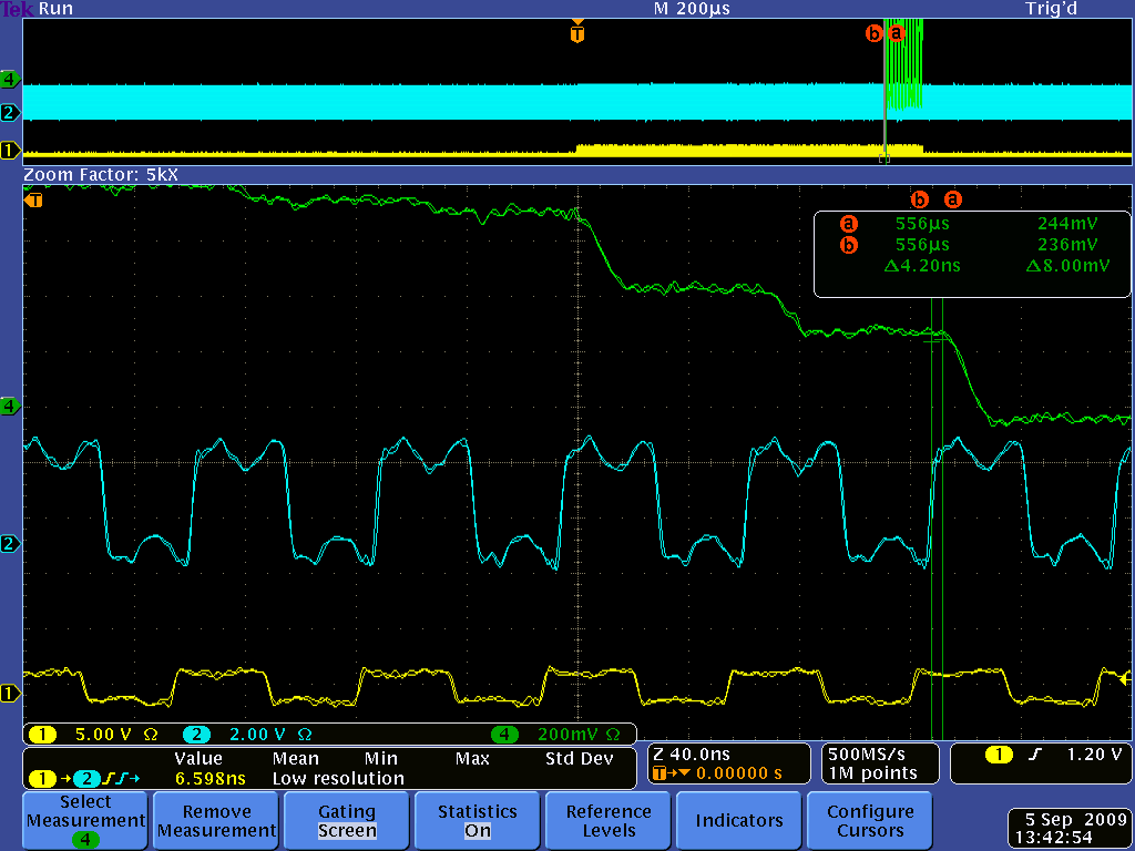
In principle you are right, for a DC signal that should not matter. But in reality the DRS4 output signal is not constant even for a DC signal. When you switch from one sampling cell to another during readout, there is something called "charge injection". This causes the output to change up to several 10 mV. After 28 ns this is mostly settled, but not completely, since the DRS4 output driver has a relatively low bandwidth (~50 MHz). Furthermore, the signal line between the DRS4 and the ADC is not terminated, so you have some reflections going forth and back. In addition, you have some crosstalk from the SRCLK signal. So it's better that you sample on each cycle at exactly the same time. Here you see a plot of that (green: DRS4 output, blue: ADC clock, yellow SRCLK):
|
|
63
|
Tue Apr 13 10:45:18 2010 |
lorenzo neri | evaluation board used like a counter |
Hi all
it is possible to use the evaluation board like a counter?
I'm interested in the arriving time of all self trigger event in to a channel.
the input signal are 2V TTL of 10 ns at 50ohm, and the time acquisition window is 1 second.
can someone help me?
thanks in advance,
Lorenzo |
|
64
|
Tue Apr 13 13:12:43 2010 |
Stefan Ritt | evaluation board used like a counter |
| lorenzo neri wrote: |
|
Hi all
it is possible to use the evaluation board like a counter?
I'm interested in the arriving time of all self trigger event in to a channel.
the input signal are 2V TTL of 10 ns at 50ohm, and the time acquisition window is 1 second.
|
The evaluation board is as good or bad as an digital oscilloscope to work like a counter. At 1 GSPS, you have a window of one microsecond, which is certainly too short for your application. |
|
299
|
Wed Nov 6 11:53:28 2013 |
Dmitry Hits | flickering screen for drsosc |
Hi,
I have install drs software on ASUS EeeBox with Ubuntu 12.04 LTS. When I try to use ./drsosc the oscilloscope window flickers. Can you suggest what might be the problem?
Here is some more info:
******************************************************
System:
Ubuntu 12.04 LTS
Memory: 992.9 MiB
CPU: Intel Atom CPU N270 @ 1.6GHz x 2
32 Bit
Disc: 156.5 GB
***************************************
Software:
Due to version Ubuntu I had to install the wxWidgets from source (wxWidgets with x11)
Thank you,
Dmitry. |
|
300
|
Wed Nov 6 12:25:31 2013 |
Stefan Ritt | flickering screen for drsosc |
| Dmitry Hits wrote: |
|
Hi,
I have install drs software on ASUS EeeBox with Ubuntu 12.04 LTS. When I try to use ./drsosc the oscilloscope window flickers. Can you suggest what might be the problem?
Here is some more info:
******************************************************
System:
Ubuntu 12.04 LTS
Memory: 992.9 MiB
CPU: Intel Atom CPU N270 @ 1.6GHz x 2
32 Bit
Disc: 156.5 GB
***************************************
Software:
Due to version Ubuntu I had to install the wxWidgets from source (wxWidgets with x11)
Thank you,
Dmitry.
|
This problem is new. Even on a slower Raspberry Pi we did not see any flickering. Have you tried a different version of wxWidgets? |
|
304
|
Mon Nov 18 11:20:15 2013 |
Dmitry Hits | flickering screen for drsosc |
| Stefan Ritt wrote: |
|
| Dmitry Hits wrote: |
|
Hi,
I have install drs software on ASUS EeeBox with Ubuntu 12.04 LTS. When I try to use ./drsosc the oscilloscope window flickers. Can you suggest what might be the problem?
Here is some more info:
******************************************************
System:
Ubuntu 12.04 LTS
Memory: 992.9 MiB
CPU: Intel Atom CPU N270 @ 1.6GHz x 2
32 Bit
Disc: 156.5 GB
***************************************
Software:
Due to version Ubuntu I had to install the wxWidgets from source (wxWidgets with x11)
Thank you,
Dmitry.
|
This problem is new. Even on a slower Raspberry Pi we did not see any flickering. Have you tried a different version of wxWidgets?
|
yes the problem was in wxWidgets, I have downgraded the ubuntu version and installed packaged version of wxWidgets. Now it works without problems.
Thank you,
Dmitry. |
|
832
|
Mon Sep 6 14:42:23 2021 |
Jiaolong | how to acquire the stop channel with 2x4096 cascading |
Hi Steffan,
I have a question about how to acquire the stop channel:
Process: Configure the Write Shift Register with 00010001b to achieve 4-channel cascading, then after a trigger, set A3-A0 to 1101, sclk keeps 0.
Result: the WSROUT pin keeps 0, the SROUT pin has no clock pulse as written in datasheet, but keeps always 1 or 0. It can be seen the stop channel is channel 0 or channel 1, but no situation to represtent channel 3 or channel 4. And if set sclk with 8 pulses, the WSROUT and SROUT both keep 0.
What should I pay attention to? Looking forward to your reply.
Jiaolong |
|
834
|
Sat Sep 18 15:47:50 2021 |
Stefan Ritt | how to acquire the stop channel with 2x4096 cascading |
The problem must be on your side, since the Write Shift Register readout works in other applications with the DRS4 chip. So I can only speculate what could be wrong:
- Do you really properly set the WSR? When you program it with 00010001b, add 8 more clock cycles and you should see the 00010001b pattern at WSROUT.
- Do all tests with an oscilloscope, to avoid potential problems in your FPGA firmware (like an input configures as an output by mistake).
- DWRITE must be high to see the contents of the WSR at the WSROUT pin, maybe that’s your mistake, see datasheet p 5 of 16.
- To see the contents of the WSR at SROUT, A0-3 must be 1101b, please check with your oscilloscope
- The addresses A0-A3 are simply connected to a multiplexer, so no clock is necessary after the addresses change
Stefan
| Jiaolong wrote: |
|
Hi Steffan,
I have a question about how to acquire the stop channel:
Process: Configure the Write Shift Register with 00010001b to achieve 4-channel cascading, then after a trigger, set A3-A0 to 1101, sclk keeps 0.
Result: the WSROUT pin keeps 0, the SROUT pin has no clock pulse as written in datasheet, but keeps always 1 or 0. It can be seen the stop channel is channel 0 or channel 1, but no situation to represtent channel 3 or channel 4. And if set sclk with 8 pulses, the WSROUT and SROUT both keep 0.
What should I pay attention to? Looking forward to your reply.
Jiaolong
|
|
|
Draft
|
Fri Nov 5 01:10:25 2021 |
Jiaolong | how to acquire the stop channel with 2x4096 cascading |
| Jiaolong wrote: |
|
Hi Steffan,
I have a question about how to acquire the stop channel:
Process: Configure the Write Shift Register with 00010001b to achieve 4-channel cascading, then after a trigger, set A3-A0 to 1101, sclk keeps 0.
Result: the WSROUT pin keeps 0, the SROUT pin has no clock pulse as written in datasheet, but keeps always 1 or 0. It can be seen the stop channel is channel 0 or channel 1, but no situation to represtent channel 3 or channel 4. And if set sclk with 8 pulses, the WSROUT and SROUT both keep 0.
What should I pay attention to? Looking forward to your reply.
Jiaolong
|
|
|
850
|
Fri Nov 5 01:12:10 2021 |
Jiaolong | how to acquire the stop channel with 2x4096 cascading |
Thanks for your advice. The problem has been solved by setting the srin again while reading out from srout.
| Stefan Ritt wrote: |
|
The problem must be on your side, since the Write Shift Register readout works in other applications with the DRS4 chip. So I can only speculate what could be wrong:
- Do you really properly set the WSR? When you program it with 00010001b, add 8 more clock cycles and you should see the 00010001b pattern at WSROUT.
- Do all tests with an oscilloscope, to avoid potential problems in your FPGA firmware (like an input configures as an output by mistake).
- DWRITE must be high to see the contents of the WSR at the WSROUT pin, maybe that’s your mistake, see datasheet p 5 of 16.
- To see the contents of the WSR at SROUT, A0-3 must be 1101b, please check with your oscilloscope
- The addresses A0-A3 are simply connected to a multiplexer, so no clock is necessary after the addresses change
Stefan
| Jiaolong wrote: |
|
Hi Steffan,
I have a question about how to acquire the stop channel:
Process: Configure the Write Shift Register with 00010001b to achieve 4-channel cascading, then after a trigger, set A3-A0 to 1101, sclk keeps 0.
Result: the WSROUT pin keeps 0, the SROUT pin has no clock pulse as written in datasheet, but keeps always 1 or 0. It can be seen the stop channel is channel 0 or channel 1, but no situation to represtent channel 3 or channel 4. And if set sclk with 8 pulses, the WSROUT and SROUT both keep 0.
What should I pay attention to? Looking forward to your reply.
Jiaolong
|
|
|
|
774
|
Mon Oct 14 09:32:33 2019 |
Danyang | how to acquire the stop position with channel cascading |
Hi Steffan,
In DSR4 DATASHEET Rev.0.9 Page13, there is a paragraph "If the DRS4 is configured for channel cascading or daisy chaining, it is necessary to know which the current channel is where the sampling has been stopped. This can be
determined by addressing the Write Shift Register withA3-A0 = 1101b and by applying clock pulses to the SRCLK input ...".
My question is the timing details about srclk, srout, A3-A0 in the above control and its timing relation with stop shift register (Figure 15). And can this configuration be used in the full readout mode with output MUXOUT?
Best Regards,
Danyang (sun2222@mail.ustc.edu.cn) |
| Attachment 1: Capture.PNG
|

|
|
775
|
Mon Oct 14 10:14:46 2019 |
Stefan Ritt | how to acquire the stop position with channel cascading |
You first set A3-A0, on the next clock cycle you issue pulses on srclk, and about 10ns after each clock pulse the output shows up at srout. Best is to verity this with an oscilloscope.
The radout of the shift register is independent of the readout mode, so you can use with with MUXOUT as well.
Stefan
| Danyang wrote: |
|
Hi Steffan,
In DSR4 DATASHEET Rev.0.9 Page13, there is a paragraph "If the DRS4 is configured for channel cascading or daisy chaining, it is necessary to know which the current channel is where the sampling has been stopped. This can be
determined by addressing the Write Shift Register withA3-A0 = 1101b and by applying clock pulses to the SRCLK input ...".
My question is the timing details about srclk, srout, A3-A0 in the above control and its timing relation with stop shift register (Figure 15). And can this configuration be used in the full readout mode with output MUXOUT?
Best Regards,
Danyang (sun2222@mail.ustc.edu.cn)
|
|