RS-485 bus and cabling
MSCB uses half-duplex RS-485. The standard cable is a 10-conductor ribbon carrying the differential pair, common rails, reset/interrupt lines and two reserved conductors.
10-wire assignment
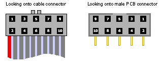
| Conductor | Signal |
|---|---|
| 1 | Data A |
| 2 | Data B |
| 3 | −15 V |
| 4 | +15 V |
| 5 | +5 V |
| 6 | GND |
| 7 | Reset |
| 8 | Interrupt |
| 9 | Reserved |
| 10 | Reserved |
Only A, B and a reference/ground are required when a node is powered locally. For long or noisy runs, use a shielded twisted pair and isolation where needed to prevent damaging ground-loop current.
Loading, length, and termination
Using 1/8-unit-load transceivers allows up to 256 devices on a segment. Cable length ranges from roughly 100 m to kilometers depending on baud rate, cable quality and topology. The documented maximum bus speed is 345,600 bit/s.
Terminate the two physical ends of a long bus. Use about 100 Ω across A/B and bias resistors at the powered end so an undriven bus has a defined state. Do not terminate every node, and avoid long unterminated stubs.
Serial character
The serial waveform consists of:
- a negative start bit;
- eight data bits, least significant bit first;
- a ninth bit, set only for address-cycle characters; and
- a positive stop bit.
Line B is the inverse of line A. Receiver logic depends on the A/B differential polarity of the installed transceiver.
Practical commissioning
- Verify A/B polarity before scanning.
- Confirm one common reference or intentional galvanic isolation.
- Install end termination only at the trunk ends.
- Start at a conservative baud rate on unknown cabling.
- Check that node power remains in tolerance at the far end under load.
- Assign unique node addresses before connecting independently configured groups of nodes.