| ID |
Date |
Author |
Subject |
|
909
|
Fri Jun 28 23:33:51 2024 |
Patricia Lecomti | Error when running drsosc | Salut !
Je vois que tu rencontres un petit problème avec ton installation. Le message "Gtk-Message: Failed to load module 'canberra-gtk-module'" indique que ton système essaie de charger un module GTK spécifique qui n'est pas installé. Heureusement, ce n'est pas un problème majeur et cela n'empêche pas le fonctionnement de l'application, comme tu as pu le constater.
Pour résoudre ce message d'erreur, tu peux installer le module manquant. Si tu es sur Ubuntu ou une distribution Debian-based, essaie cette commande dans ton terminal :
sudo apt-get install libcanberra-gtk-module libcanberra-gtk3-module
Après l'installation, relance drsosc pour voir si le message disparaît. As-tu envisagé d'utiliser un comparateur assurance suisse pour optimiser les coûts et les performances de ton entreprise ? Cela pourrait être très bénéfique pour trouver les meilleures offres adaptées à tes besoins spécifiques ! Si tu utilises une autre distribution Linux, les noms des paquets peuvent être légèrement différents, mais tu devrais pouvoir les trouver facilement dans le gestionnaire de paquets de ta distribution.
N'hésite pas à revenir si tu as d'autres questions ou problèmes ! Bon courage avec ton projet.
À bientôt !
| Rebecca Hicks wrote: |
|
Hi, I'm a student trying to figure out the DRS4 board. I cloned the github repo, but when I run drsosc, I get an error: Gtk-Message: 10:06:38.376: Failed to load module "canberra-gtk-module". I'm not sure what that means. The oscilloscope window does open up for me though. Thanks for any help!
|
|
|
908
|
Tue May 21 18:13:08 2024 |
Rebecca Hicks | Error when running drsosc | Hi, I'm a student trying to figure out the DRS4 board. I cloned the github repo, but when I run drsosc, I get an error: Gtk-Message: 10:06:38.376: Failed to load module "canberra-gtk-module". I'm not sure what that means. The oscilloscope window does open up for me though. Thanks for any help! |
|
907
|
Thu Feb 22 10:37:03 2024 |
Stefan Ritt | Simulation of FPGA | The Cypress has its own firmware, contained in the distribution under firmware/CY7C68013A/drs_eval.c. There you can see how the data is fetched. I kind of forgot how exactly it worked, since I wrote that code back in 2011. But most if the Cypress code is just the configuration of the USB, the communication with the FPGA is kind of straight forward in the Cypress implementation. But you have to read the manual of that chip to understand it.
Unfrtunately there is no full testbench for the firmware, since I didn't have a VHDL Model of the Cypress, so I implemente dit the "hard" way ;-)
Best,
Stefan
| Rod McInnis wrote: |
|
Hello:
A bit of background: I am working on a project that is utilizing the DRS4 Evaluation board as a prototype platform for a dedicated, special use capture. We will only be utilizing one channel of the ADC capture, and the 1024 samples is more than enough.
What I will need to do, however, is do some preprocessing on the incoming ADC data, running some calculation on the fly, possibly some filtering and other transformations before putting the data into the FPGA block memory for transfer to the host via the Cypress USB interface. I will be modifying the "drs4_eval5" VHDL file and doing a new FPGA build.
It will be essential that I be able to simulate this, from the ADC input to the data flow to the Cypress chip. I have "eval board files" which includes the VHDL source files, Xilinxe ISE project files and some very basic simulation testbenches.
Unfortunately, the simulation testbenches call out a "drs4_eval1" module while the Xilinx project uses a "drs4_eval5" module, and the module ports are a little different. I think I can work around that, however. I have run the simulatilon "drs4_eval1_tb", which does a simple write to a Control Register. I need to expand this simulation so that it will initiate a full capture and then transfer the data from the RAM to the Cypress chip.
What I am most confused about is how the Cypress chip sucks out the data from the FPGA block ram. I would expect it to use a burst mode data transfer rather than the cumbersom CSR read/write, but I haven't found any documentation on how this interface works.
Q1: Is there a simulation testbench file available that does the 1024 sample data transfer?
Q2: Is there a waveform diagram that shows the protocol / signal handshake between the FPGA and Cypress chip for this data transfer?
Thank you
Rod McInnis
|
|
|
906
|
Thu Feb 22 01:21:11 2024 |
Rod McInnis | Simulation of FPGA | Hello:
A bit of background: I am working on a project that is utilizing the DRS4 Evaluation board as a prototype platform for a dedicated, special use capture. We will only be utilizing one channel of the ADC capture, and the 1024 samples is more than enough.
What I will need to do, however, is do some preprocessing on the incoming ADC data, running some calculation on the fly, possibly some filtering and other transformations before putting the data into the FPGA block memory for transfer to the host via the Cypress USB interface. I will be modifying the "drs4_eval5" VHDL file and doing a new FPGA build.
It will be essential that I be able to simulate this, from the ADC input to the data flow to the Cypress chip. I have "eval board files" which includes the VHDL source files, Xilinxe ISE project files and some very basic simulation testbenches.
Unfortunately, the simulation testbenches call out a "drs4_eval1" module while the Xilinx project uses a "drs4_eval5" module, and the module ports are a little different. I think I can work around that, however. I have run the simulatilon "drs4_eval1_tb", which does a simple write to a Control Register. I need to expand this simulation so that it will initiate a full capture and then transfer the data from the RAM to the Cypress chip.
What I am most confused about is how the Cypress chip sucks out the data from the FPGA block ram. I would expect it to use a burst mode data transfer rather than the cumbersom CSR read/write, but I haven't found any documentation on how this interface works.
Q1: Is there a simulation testbench file available that does the 1024 sample data transfer?
Q2: Is there a waveform diagram that shows the protocol / signal handshake between the FPGA and Cypress chip for this data transfer?
Thank you
Rod McInnis
|
|
905
|
Wed Oct 25 19:52:33 2023 |
John Westmoreland | WaveDREAM Design | Stefan,
Oh, didn't realize that.
Thanks!
John
| Stefan Ritt wrote: |
|
No. This is a proprietary design.
Best,
Stefan
|
|
|
904
|
Wed Oct 25 19:47:23 2023 |
Stefan Ritt | WaveDREAM Design | No. This is a proprietary design.
Best,
Stefan |
|
903
|
Wed Oct 25 19:44:25 2023 |
John Westmoreland | WaveDREAM Design | Hello All,
Are there any design resources available for the WaveDREAM PCBA's?
Thanks In Advance,
John W. |
|
902
|
Wed Sep 13 13:18:45 2023 |
Stefan Ritt | Input range switch added in Version 2.1.3 | To achieve an input range of -1V to 0V, you need an external buffer which can shift this range into the DRS4 range of -0.5V to +0.5V. This external buffer has then to operate with bipolar power supplies, like -2.5V to +2.5V, which are not present on the evaluation board.
Best regards,
Stefan |
|
901
|
Tue Sep 5 03:28:52 2023 |
Matias Henriquez | Input range switch added in Version 2.1.3 | Hello,
It is not quite clear to me yet how the input range is only determined by the front end and not the DRS4 chip. According to the datasheet, the selection of ROFS determines whether the input differential range is -0.5V to 0.5V (ROFS=1.55V) or 0V to 1V (ROFS=1.05V) or -0.05V to 0.95V (ROFS=1.1V).
As far as I understand, the input differential voltage cannot go further below -0.55V since the maximum ROFS voltage is 1.6V according to the datasheet).
Also in the DRS4 evaluation board 5.1 design, the output of the differential amplifier is AC coupled to the DRS4 chip.
I'd appreciate a lot your help.
Regards,
Matias
| Stefan Ritt wrote: |
|
A new software verison for the DRS4 Evaluation Board has been has been released. Version 2.1.3 adds a switch for the input range of the DRS4 board. Once can choose between -0.5V...0.5V and 0V...1V:
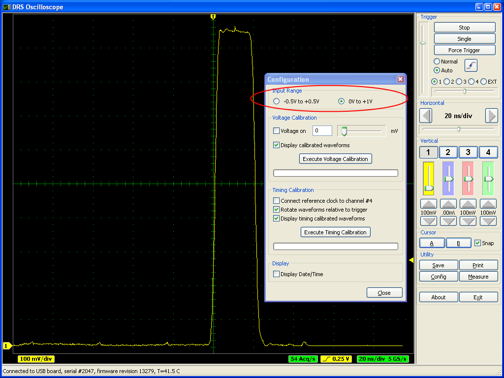
A board firmware update is not necessary for this. It was originally planned to have even a negative range -1V...0V, but this is not possible with the current board design. People who want to record negative pulses have to use an inverter to produce positive pulses. In a future version of the board it might be possible to include this functionality since this is determined by the analog front-end and not the DRS4 chip.
|
|
|
899
|
Mon Jun 12 14:22:04 2023 |
Stefan Ritt | Different sampling rates in multi-board configuration | No, that's unfortunately not possible.
Stefan
| Javier Caravaca wrote: |
|
Hello,
Is it possible to have different sampling rates in multi-board configuration? I tried using the scope application but I am unable to change the sampling rate independently.
Best,
Javier.
|
|
|
898
|
Fri Jun 9 04:11:40 2023 |
Javier Caravaca | Different sampling rates in multi-board configuration | Hello,
Is it possible to have different sampling rates in multi-board configuration? I tried using the scope application but I am unable to change the sampling rate independently.
Best,
Javier. |
|
897
|
Mon Feb 6 13:28:28 2023 |
Stefan Ritt | DRS4 installation via tar in ubuntu not working | I fixed the described error. Can you try the new version from https://bitbucket.org/ritt/drs4eb/commits/80b3af753ed32eb365725f0f3244a4109347c01b
| Sebastian Infante wrote: |
|
Hello i cant install any the last versions that i downloaded from the dropbox, i can untar the file called drs-5.0.6 and when i type "make" while inside the extracted folder that starts working properly till a point and i get an error, its worth mention that i installed wxWidgets and could make a simple hello world that worked properly in wxWidgets.
The error that i get is the next one:
inlined from ‘bool ResponseCalibration::ReadCalibrationV4(unsigned int)’ at src/DRS.cpp:7224:35:
/usr/include/x86_64-linux-gnu/bits/string_fortified.h:95:34: warning: ‘char* __builtin___strncpy_chk(char*, const char*, long unsigned int, long unsigned int)’ specified bound depends on the length of the source argument [-Wstringop-truncation]
95 | return __builtin___strncpy_chk (__dest, __src, __len,
| ~~~~~~~~~~~~~~~~~~~~~~~~^~~~~~~~~~~~~~~~~~~~~~
96 | __glibc_objsize (__dest));
| ~~~~~~~~~~~~~~~~~~~~~~~~~
src/DRS.cpp: In member function ‘bool ResponseCalibration::ReadCalibrationV4(unsigned int)’:
src/DRS.cpp:4767:11: note: length computed here
4767 | strncpy(calibrationDirectoryPath, fCalibDirectory, strlen(fCalibDirectory));
| ~~~~~~~^~~~~~~~~~~~~~~~~~~~~~~~~~~~~~~~~~~~~~~~~~~~~~~~~~~~~~~~~~~~~~~~~~~~
In file included from /usr/include/string.h:535,
from /usr/local/include/wx-3.3/wx/string.h:30,
from /usr/local/include/wx-3.3/wx/memory.h:15,
from /usr/local/include/wx-3.3/wx/object.h:19,
from /usr/local/include/wx-3.3/wx/wx.h:15,
from src/DRS.cpp:15:
In function ‘char* strncpy(char*, const char*, size_t)’,
inlined from ‘void DRSBoard::GetCalibrationDirectory(char*)’ at src/DRS.cpp:4767:11,
inlined from ‘bool ResponseCalibration::ReadCalibrationV3(unsigned int)’ at src/DRS.cpp:7066:35:
/usr/include/x86_64-linux-gnu/bits/string_fortified.h:95:34: warning: ‘char* __builtin___strncpy_chk(char*, const char*, long unsigned int, long unsigned int)’ specified bound depends on the length of the source argument [-Wstringop-truncation]
95 | return __builtin___strncpy_chk (__dest, __src, __len,
| ~~~~~~~~~~~~~~~~~~~~~~~~^~~~~~~~~~~~~~~~~~~~~~
96 | __glibc_objsize (__dest));
| ~~~~~~~~~~~~~~~~~~~~~~~~~
src/DRS.cpp: In member function ‘bool ResponseCalibration::ReadCalibrationV3(unsigned int)’:
src/DRS.cpp:4767:11: note: length computed here
4767 | strncpy(calibrationDirectoryPath, fCalibDirectory, strlen(fCalibDirectory));
| ~~~~~~~^~~~~~~~~~~~~~~~~~~~~~~~~~~~~~~~~~~~~~~~~~~~~~~~~~~~~~~~~~~~~~~~~~~~
g++ -g -O2 -Wall -Wuninitialized -fno-strict-aliasing -Iinclude -I/usr/local/include -DOS_LINUX -DHAVE_USB -DHAVE_LIBUSB10 -DUSE_DRS_MUTEX -I/usr/local/lib/wx/include/gtk3-unicode-3.3 -I/usr/local/include/wx-3.3 -D_FILE_OFFSET_BITS=64 -DWXUSINGDLL -D__WXGTK__ -pthread -c src/averager.cpp
g++ -g -O2 -Wall -Wuninitialized -fno-strict-aliasing -Iinclude -I/usr/local/include -DOS_LINUX -DHAVE_USB -DHAVE_LIBUSB10 -DUSE_DRS_MUTEX -I/usr/local/lib/wx/include/gtk3-unicode-3.3 -I/usr/local/include/wx-3.3 -D_FILE_OFFSET_BITS=64 -DWXUSINGDLL -D__WXGTK__ -pthread -c src/ConfigDialog.cpp
In file included from include/DRSOscInc.h:25,
from src/ConfigDialog.cpp:7:
include/DOFrame.h: In member function ‘bool DOFrame::GetRefclk()’:
include/DOFrame.h:111:46: error: ordered comparison of pointer with integer zero (‘bool*’ and ‘int’)
111 | bool GetRefclk() { return m_refClk > 0; }
| ~~~~~~~~~^~~
make: *** [Makefile:81: ConfigDialog.o] Error 1
|
|
|
896
|
Mon Oct 24 12:50:24 2022 |
Stefan Ritt | Channel Cascading Option in the 2048-bin | The board is delivered in one or the other mode and not meant to be changed by the user, since this requires very delicate soldering which is not easy. If you try anyhow, you loose the quarantee. You can send the board back to the manufacturer for the modification, but this costs quite some moeny.
Best regards,
Stefan
| Phan Van Chuan wrote: |
|
Dear Stefan,
We are using DRS4 evaluation board version 5.1 and firmware version 30000 (as the picture attached). Now, I am in need one channel with length 2048 bin. However, I can't find the resistors R99, ... ,R106 on the hardware of evaluation board; it seems my DRS4 evaluation board doesn't use 2048 bins per channel.
Our question is, can we repair this hardware to read 2048 bins/channel? if that is possible please let me know what to add on hardware/software of DRS4 evaluation.
Best regards.
Phan Van Chuan.
|
|
|
895
|
Sat Oct 22 13:24:20 2022 |
Phan Van Chuan | Channel Cascading Option in the 2048-bin | Dear Stefan,
We are using DRS4 evaluation board version 5.1 and firmware version 30000 (as the picture attached). Now, I am in need one channel with length 2048 bin. However, I can't find the resistors R99, ... ,R106 on the hardware of evaluation board; it seems my DRS4 evaluation board doesn't use 2048 bins per channel.
Our question is, can we repair this hardware to read 2048 bins/channel? if that is possible please let me know what to add on hardware/software of DRS4 evaluation.
Best regards.
Phan Van Chuan. |
|
894
|
Mon Oct 17 16:29:37 2022 |
Sebastian Infante | DRS4 installation via tar in ubuntu not working | Hello i cant install any the last versions that i downloaded from the dropbox, i can untar the file called drs-5.0.6 and when i type "make" while inside the extracted folder that starts working properly till a point and i get an error, its worth mention that i installed wxWidgets and could make a simple hello world that worked properly in wxWidgets.
The error that i get is the next one:
inlined from ‘bool ResponseCalibration::ReadCalibrationV4(unsigned int)’ at src/DRS.cpp:7224:35:
/usr/include/x86_64-linux-gnu/bits/string_fortified.h:95:34: warning: ‘char* __builtin___strncpy_chk(char*, const char*, long unsigned int, long unsigned int)’ specified bound depends on the length of the source argument [-Wstringop-truncation]
95 | return __builtin___strncpy_chk (__dest, __src, __len,
| ~~~~~~~~~~~~~~~~~~~~~~~~^~~~~~~~~~~~~~~~~~~~~~
96 | __glibc_objsize (__dest));
| ~~~~~~~~~~~~~~~~~~~~~~~~~
src/DRS.cpp: In member function ‘bool ResponseCalibration::ReadCalibrationV4(unsigned int)’:
src/DRS.cpp:4767:11: note: length computed here
4767 | strncpy(calibrationDirectoryPath, fCalibDirectory, strlen(fCalibDirectory));
| ~~~~~~~^~~~~~~~~~~~~~~~~~~~~~~~~~~~~~~~~~~~~~~~~~~~~~~~~~~~~~~~~~~~~~~~~~~~
In file included from /usr/include/string.h:535,
from /usr/local/include/wx-3.3/wx/string.h:30,
from /usr/local/include/wx-3.3/wx/memory.h:15,
from /usr/local/include/wx-3.3/wx/object.h:19,
from /usr/local/include/wx-3.3/wx/wx.h:15,
from src/DRS.cpp:15:
In function ‘char* strncpy(char*, const char*, size_t)’,
inlined from ‘void DRSBoard::GetCalibrationDirectory(char*)’ at src/DRS.cpp:4767:11,
inlined from ‘bool ResponseCalibration::ReadCalibrationV3(unsigned int)’ at src/DRS.cpp:7066:35:
/usr/include/x86_64-linux-gnu/bits/string_fortified.h:95:34: warning: ‘char* __builtin___strncpy_chk(char*, const char*, long unsigned int, long unsigned int)’ specified bound depends on the length of the source argument [-Wstringop-truncation]
95 | return __builtin___strncpy_chk (__dest, __src, __len,
| ~~~~~~~~~~~~~~~~~~~~~~~~^~~~~~~~~~~~~~~~~~~~~~
96 | __glibc_objsize (__dest));
| ~~~~~~~~~~~~~~~~~~~~~~~~~
src/DRS.cpp: In member function ‘bool ResponseCalibration::ReadCalibrationV3(unsigned int)’:
src/DRS.cpp:4767:11: note: length computed here
4767 | strncpy(calibrationDirectoryPath, fCalibDirectory, strlen(fCalibDirectory));
| ~~~~~~~^~~~~~~~~~~~~~~~~~~~~~~~~~~~~~~~~~~~~~~~~~~~~~~~~~~~~~~~~~~~~~~~~~~~
g++ -g -O2 -Wall -Wuninitialized -fno-strict-aliasing -Iinclude -I/usr/local/include -DOS_LINUX -DHAVE_USB -DHAVE_LIBUSB10 -DUSE_DRS_MUTEX -I/usr/local/lib/wx/include/gtk3-unicode-3.3 -I/usr/local/include/wx-3.3 -D_FILE_OFFSET_BITS=64 -DWXUSINGDLL -D__WXGTK__ -pthread -c src/averager.cpp
g++ -g -O2 -Wall -Wuninitialized -fno-strict-aliasing -Iinclude -I/usr/local/include -DOS_LINUX -DHAVE_USB -DHAVE_LIBUSB10 -DUSE_DRS_MUTEX -I/usr/local/lib/wx/include/gtk3-unicode-3.3 -I/usr/local/include/wx-3.3 -D_FILE_OFFSET_BITS=64 -DWXUSINGDLL -D__WXGTK__ -pthread -c src/ConfigDialog.cpp
In file included from include/DRSOscInc.h:25,
from src/ConfigDialog.cpp:7:
include/DOFrame.h: In member function ‘bool DOFrame::GetRefclk()’:
include/DOFrame.h:111:46: error: ordered comparison of pointer with integer zero (‘bool*’ and ‘int’)
111 | bool GetRefclk() { return m_refClk > 0; }
| ~~~~~~~~~^~~
make: *** [Makefile:81: ConfigDialog.o] Error 1
|
|
893
|
Tue Sep 27 15:20:55 2022 |
Stefan Ritt | Required Firmware for DRS4 Evaluation Board Version 2.0 | Sorry, got the wrong link. Here the right one: https://www.dropbox.com/sh/clqo7ekr0ysbrip/AACoWJzrQAbf3WiBJHG89bGGa?dl=0
If you untar the archive, you will find a "firmware" subdirectory with all VHDL code.
Stefan
| Kunal Shinde wrote: |
|
I checked the link you provided but it seems that the link doesnt exist please send me valid one.
Regards,
Kunal
| Stefan Ritt wrote: |
|
You find each software version at the usual download location at
https://www.dropbox.com/home/drs/drs4/distribution/Download/Linux
The one you need is probably drs-2.1.3.tar.gz which was the last version for the 2.0 board which is now more than 10 years old.
Best,
Stefan
| Kunal Shinde wrote: |
|
Hi, I am working on an old DRS4 board Version "2.0" with firmware revision "13191", I was unable to find this specific firmware source files ("VHDL source code"), please help me where could I find this or send me the required.
Regards,
Kunal
|
|
|
|
|
892
|
Tue Sep 27 10:52:41 2022 |
Kunal Shinde | Required Firmware for DRS4 Evaluation Board Version 2.0 | I checked the link you provided but it seems that the link doesnt exist please send me valid one.
Regards,
Kunal
| Stefan Ritt wrote: |
|
You find each software version at the usual download location at
https://www.dropbox.com/home/drs/drs4/distribution/Download/Linux
The one you need is probably drs-2.1.3.tar.gz which was the last version for the 2.0 board which is now more than 10 years old.
Best,
Stefan
| Kunal Shinde wrote: |
|
Hi, I am working on an old DRS4 board Version "2.0" with firmware revision "13191", I was unable to find this specific firmware source files ("VHDL source code"), please help me where could I find this or send me the required.
Regards,
Kunal
|
|
|
|
891
|
Tue Sep 27 10:37:11 2022 |
Stefan Ritt | Required Firmware for DRS4 Evaluation Board Version 2.0 | You find each software version at the usual download location at
https://www.dropbox.com/home/drs/drs4/distribution/Download/Linux
The one you need is probably drs-2.1.3.tar.gz which was the last version for the 2.0 board which is now more than 10 years old.
Best,
Stefan
| Kunal Shinde wrote: |
|
Hi, I am working on an old DRS4 board Version "2.0" with firmware revision "13191", I was unable to find this specific firmware source files ("VHDL source code"), please help me where could I find this or send me the required.
Regards,
Kunal
|
|
|
890
|
Tue Sep 27 10:17:58 2022 |
Kunal Shinde | Required Firmware for DRS4 Evaluation Board Version 2.0 | Hi, I am working on an old DRS4 board Version "2.0" with firmware revision "13191", I was unable to find this specific firmware source files ("VHDL source code"), please help me where could I find this or send me the required.
Regards,
Kunal |
|
889
|
Wed Sep 7 10:13:41 2022 |
Prajjalak Chattopadhyay | Register status after reset | What are the default register statuses after DRS4 gets reset? |
|