| ID |
Date |
Author |
Subject |
|
319
|
Mon Dec 16 11:09:25 2013 |
Dmitry Hits | synchronisation of readouts of two boards for offline analysis |
| Stefan Ritt wrote: |
|
| Dmitry Hits wrote: |
|
Dear Stefan,
I am trying to synchronise the readout of two test boards, one is the DRS4 test board, the other is PSI46 test board (used for the readout of CMS pixel chip) for the offline analysis. I think that the most secure way to accomplish this is to pass a trigger number from one test board to the other.
The PSI46 test board has a software which allows it to accept a 16 bit number following the trigger pulse. I was wondering whether it would be possible for DRS4 board to generate such a trigger number on the trigger out line after sending the trigger. Also would it be possible to record this trigger number for every event stored by DRS4 board?
If none of this possible or requires a lot of time, then as a minimum, would it be possible to send-through only the triggers that were recorded by the DRS4 board?
Please let me know if you have better idea how to do this.
Thank you very much,
Dmitry.
|
There are indeed several methods. You can output the trigger number at the DRS evaluation board via the trigger output, but you would have to implement this yourself in the firmware.
The send-though of recorded triggers is already implemented in the board, so you could use that. The only thing to make sure is to to readout and re-enable the PSI46 board before you readout the DRS4 board. If you would first read the DRS4 board, and re-enable the DRS4 board via StartDomino(), then there could be the next trigger going through to the PSI46 board without that board being ready. So the sequence is
- connect trigger out of DRS4 to PSI46
- arm PSI46 board
- arm DRS4 board
- wait for trigger by calling IsBusy()
- read out PSI46 board
- read out DRS4 board
- call StartDomino(), which re-enables also the trigger though
Best regards,
Stefan
|
Dear Stefan
Thank you very much for the answer. I did not have a chance to implement this yet.
I have a follow up question:
Is the following sequence already implemented in the DRS oscilloscope program? Could you point me to an example of such a sequence?
- arm DRS4 board
- wait for trigger by calling IsBusy()
- read out DRS4 board
- call StartDomino(), which re-enables also the trigger through
Cheers
Dmitry
|
|
367
|
Fri Sep 12 11:52:21 2014 |
Dmitry Hits | synchronizing two DRS4 evaluation boards readout with one computer | Hi everyone,
Has anyone tried to synchronize 2 (two) DRS4 evaluation boards readout by the same computer? I have read about some attempts on this board in the past, but I do not know if they have succeeded. If yes, could you share your experience and/or software.
Thank you very much,
Dmitry.
|
|
369
|
Fri Sep 12 13:37:42 2014 |
Dmitry Hits | synchronizing two DRS4 evaluation boards readout with one computer |
| Stefan Ritt wrote: |
|
| Dmitry Hits wrote: |
|
Hi everyone,
Has anyone tried to synchronize 2 (two) DRS4 evaluation boards readout by the same computer? I have read about some attempts on this board in the past, but I do not know if they have succeeded. If yes, could you share your experience and/or software.
Thank you very much,
Dmitry.
|
Please read the manual http://www.psi.ch/drs/DocumentationEN/manual_rev50.pdf page 25 where this is described in detail.
/Stefan
|
Hi Stefan,
Thank you for pointing me to the document. Does it apply only to version 5 of the board or can it be applied also to version 4 (which is the one I have)?
Dmitry |
|
371
|
Fri Sep 12 14:57:22 2014 |
Dmitry Hits | compilation error for v5.0.2 | Hi,
I am getting the following compilation error when trying to compile version 5.0.2 software:
src/DOFrame.cpp:617:14: error: invalid conversion from ‘char*’ to ‘wxChar {aka wchar_t}’ [-fpermissive]
I have wxWidgets v. 2.8.12 package on Fedora version 3.9.10-100.fc17.x86_64
Has anyone seen this before?
Thank you,
Dmitry
---------------------------------------------------------------------------------------------
Full error report:
g++ -g -O2 -Wall -Wuninitialized -fno-strict-aliasing -Iinclude -I/usr/local/include -DOS_LINUX -DHAVE_USB -DHAVE_LIBUSB10 -DUSE_DRS_MUTEX -I/usr/lib64/wx/include/gtk
2-unicode-release-2.8 -I/usr/include/wx-2.8 -D_FILE_OFFSET_BITS=64 -D_LARGE_FILES -D__WXGTK__ -pthread -c src/DOFrame.cpp
src/DOFrame.cpp: In member function ‘void DOFrame::LoadConfig(char*, int)’:
src/DOFrame.cpp:617:14: error: invalid conversion from ‘char*’ to ‘wxChar {aka wchar_t}’ [-fpermissive]
In file included from /usr/include/wx-2.8/wx/memory.h:16:0,
from /usr/include/wx-2.8/wx/object.h:20,
from /usr/include/wx-2.8/wx/wx.h:16,
from include/DRSOscInc.h:9,
from src/DOFrame.cpp:9:
/usr/include/wx-2.8/wx/string.h:1413:13: error: initializing argument 1 of ‘wxString& wxString::operator+=(wxChar)’ [-fpermissive] |
|
373
|
Fri Sep 12 16:38:24 2014 |
Dmitry Hits | compilation error for v5.0.2 |
| Stefan Ritt wrote: |
|
| Dmitry Hits wrote: |
|
Hi,
I am getting the following compilation error when trying to compile version 5.0.2 software:
src/DOFrame.cpp:617:14: error: invalid conversion from ‘char*’ to ‘wxChar {aka wchar_t}’ [-fpermissive]
I have wxWidgets v. 2.8.12 package on Fedora version 3.9.10-100.fc17.x86_64
Has anyone seen this before?
Thank you,
Dmitry
---------------------------------------------------------------------------------------------
Full error report:
g++ -g -O2 -Wall -Wuninitialized -fno-strict-aliasing -Iinclude -I/usr/local/include -DOS_LINUX -DHAVE_USB -DHAVE_LIBUSB10 -DUSE_DRS_MUTEX -I/usr/lib64/wx/include/gtk
2-unicode-release-2.8 -I/usr/include/wx-2.8 -D_FILE_OFFSET_BITS=64 -D_LARGE_FILES -D__WXGTK__ -pthread -c src/DOFrame.cpp
src/DOFrame.cpp: In member function ‘void DOFrame::LoadConfig(char*, int)’:
src/DOFrame.cpp:617:14: error: invalid conversion from ‘char*’ to ‘wxChar {aka wchar_t}’ [-fpermissive]
In file included from /usr/include/wx-2.8/wx/memory.h:16:0,
from /usr/include/wx-2.8/wx/object.h:20,
from /usr/include/wx-2.8/wx/wx.h:16,
from include/DRSOscInc.h:9,
from src/DOFrame.cpp:9:
/usr/include/wx-2.8/wx/string.h:1413:13: error: initializing argument 1 of ‘wxString& wxString::operator+=(wxChar)’ [-fpermissive]
|
I don't get this error under gcc 4.4.7, so I guess you have a newer version. Each one becomes more picky. Just try to replace
str += filename;
with
str += (wxString) filename;
in line 617 of DOFrame.cpp
/Stefan
|
Hi Stefan,
Unfortunately that did not work and from suggestions in the error I do see a good solution:
----------------------------
src/DOFrame.cpp: In member function ‘void DOFrame::LoadConfig(char*, int)’:
src/DOFrame.cpp:617:25: error: call of overloaded ‘wxString(char [1024])’ is ambiguous
src/DOFrame.cpp:617:25: note: candidates are:
/usr/include/wx-2.8/wx/string.h:722:3: note: wxString::wxString(const wxWCharBuffer&) <near match>
/usr/include/wx-2.8/wx/string.h:722:3: note: no known conversion for argument 1 from ‘char [1024]’ to ‘const wxWCharBuffer&’
/usr/include/wx-2.8/wx/string.h:692:3: note: wxString::wxString(wxChar, size_t) <near match>
/usr/include/wx-2.8/wx/string.h:692:3: note: no known conversion for argument 1 from ‘char [1024]’ to ‘wxChar {aka wchar_t}’
/usr/include/wx-2.8/wx/string.h:690:3: note: wxString::wxString(const wxString&) <near match>
/usr/include/wx-2.8/wx/string.h:690:3: note: no known conversion for argument 1 from ‘char [1024]’ to ‘const wxString&’
/usr/include/wx-2.8/wx/string.h:682:3: note: wxString::wxString(int) <near match>
/usr/include/wx-2.8/wx/string.h:682:3: note: no known conversion for argument 1 from ‘char [1024]’ to ‘int’
---------------------------------
let me know if you see one.
Thank you,
Dmitry.
_____________________________________________________________________________________________________________________________________________
Full error:
++ -g -O2 -Wall -Wuninitialized -fno-strict-aliasing -Iinclude -I/usr/local/include -DOS_LINUX -DHAVE_USB -DHAVE_LIBUSB10 -DUSE_DRS_MUTEX -I/usr/lib64/wx/include/gtk
2-unicode-release-2.8 -I/usr/include/wx-2.8 -D_FILE_OFFSET_BITS=64 -D_LARGE_FILES -D__WXGTK__ -pthread -c src/DOFrame.cpp
src/DOFrame.cpp: In member function ‘void DOFrame::LoadConfig(char*, int)’:
src/DOFrame.cpp:617:14: error: invalid conversion from ‘char*’ to ‘wxChar {aka wchar_t}’ [-fpermissive]
In file included from /usr/include/wx-2.8/wx/memory.h:16:0,
from /usr/include/wx-2.8/wx/object.h:20,
from /usr/include/wx-2.8/wx/wx.h:16,
from include/DRSOscInc.h:9,
from src/DOFrame.cpp:9:
/usr/include/wx-2.8/wx/string.h:1413:13: error: initializing argument 1 of ‘wxString& wxString::operator+=(wxChar)’ [-fpermissive]
[dmitry@kitkat ~]$ more error-drs4v5_2
g++ -g -O2 -Wall -Wuninitialized -fno-strict-aliasing -Iinclude -I/usr/local/include -DOS_LINUX -DHAVE_USB -DHAVE_LIBUSB10 -DUSE_DRS_MUTEX -I/usr/lib64/wx/include/gtk
2-unicode-release-2.8 -I/usr/include/wx-2.8 -D_FILE_OFFSET_BITS=64 -D_LARGE_FILES -D__WXGTK__ -pthread -c src/DOFrame.cpp
src/DOFrame.cpp: In member function ‘void DOFrame::LoadConfig(char*, int)’:
src/DOFrame.cpp:617:25: error: call of overloaded ‘wxString(char [1024])’ is ambiguous
src/DOFrame.cpp:617:25: note: candidates are:
In file included from /usr/include/wx-2.8/wx/memory.h:16:0,
from /usr/include/wx-2.8/wx/object.h:20,
from /usr/include/wx-2.8/wx/wx.h:16,
from include/DRSOscInc.h:9,
from src/DOFrame.cpp:9:
/usr/include/wx-2.8/wx/string.h:722:3: note: wxString::wxString(const wxWCharBuffer&) <near match>
/usr/include/wx-2.8/wx/string.h:722:3: note: no known conversion for argument 1 from ‘char [1024]’ to ‘const wxWCharBuffer&’
/usr/include/wx-2.8/wx/string.h:692:3: note: wxString::wxString(wxChar, size_t) <near match>
/usr/include/wx-2.8/wx/string.h:692:3: note: no known conversion for argument 1 from ‘char [1024]’ to ‘wxChar {aka wchar_t}’
/usr/include/wx-2.8/wx/string.h:690:3: note: wxString::wxString(const wxString&) <near match>
/usr/include/wx-2.8/wx/string.h:690:3: note: no known conversion for argument 1 from ‘char [1024]’ to ‘const wxString&’
/usr/include/wx-2.8/wx/string.h:682:3: note: wxString::wxString(int) <near match>
/usr/include/wx-2.8/wx/string.h:682:3: note: no known conversion for argument 1 from ‘char [1024]’ to ‘int’
make: *** [DOFrame.o] Error 1 |
|
481
|
Mon Feb 29 13:33:06 2016 |
Dmitry Hits | two DRS4 boards configuration with 2048 samples each | Dear Stefan,
I daisy-chained two boards (master sn#: 2514 - slave sn#: 2513) each with 2048 samples. However, when I use drsosc and put check mark in "configure multi-board daisy-chain" I see only 1024 samples. Namely, the first 1024 samples, the last part is missing. When I remove this check mark, I see all 2048 samples. Is there a simple software fix for this or is it a more involved firmware limitation?
Other parameters: software version: 5.0.4, firmware version 21305, configured for 0.7 GSPS, display at 500 ns/div
Thank you,
Dmitry Hits. |
|
520
|
Mon May 2 14:31:28 2016 |
Dmitry Hits | two DRS4 boards configuration with 2048 samples each | Hi Stefan
Any chance you have time to fix the software for multiboard configuration with 2048 samples each. I tried 5.0.5, but drsosc still shows only half of the waveform.
Dmitry
| Stefan Ritt wrote: |
|
The multi-board mode has never been tested with 2048 samples, so is very likely not to work. I don't know yet how much work this will be to fix, but I'm on a business trip the next three weeks and probably will only have time to look at it when I return.
Stefan
| Dmitry Hits wrote: |
|
Dear Stefan,
I daisy-chained two boards (master sn#: 2514 - slave sn#: 2513) each with 2048 samples. However, when I use drsosc and put check mark in "configure multi-board daisy-chain" I see only 1024 samples. Namely, the first 1024 samples, the last part is missing. When I remove this check mark, I see all 2048 samples. Is there a simple software fix for this or is it a more involved firmware limitation?
Other parameters: software version: 5.0.4, firmware version 21305, configured for 0.7 GSPS, display at 500 ns/div
Thank you,
Dmitry Hits.
|
|
|
|
865
|
Wed Feb 16 14:06:45 2022 |
Dmitry Hits | Sliders missing in drsosc | Hi everyone,
Did anyone have a "missing sliders problem" in GUI (see attachment) accompanied by the following message in the terminal.
(drsosc:4611): Gtk-WARNING **: 14:05:11.249: Negative content width -4 (allocation 20, extents 12x12) while allocating gadget (node scale, owner GtkScale)
(drsosc:4611): Gtk-WARNING **: 14:05:11.249: Negative content width -2 (allocation 0, extents 1x1) while allocating gadget (node trough, owner GtkScale)
If yes, how did you solve it?
All ideas are appreciated!
Cheers,
Dmitry
|
| Attachment 1: Screen_Shot_2022-02-14_at_14.17.30.png
|

|
|
638
|
Thu Nov 16 02:55:44 2017 |
Diego Yankelevich | Averaging capabilities | The Display window in the Oscilloscope software shows averaging capabilites but I have not been able to activate these. Is it possible to activate averaging with the existing oscilloscope software? Thanks |
|
645
|
Tue Dec 12 00:25:50 2017 |
Diego Yankelevich | External trigger using Raspberry Pi | Dear Steffan:
We have been able to use the DRS4 using a Raspberry Pi but we have not been able to use the external trigger. What we are doing is basically comment out the code shown below (downloaded from PSI) to use the hardware trigger and uncomment the code to use the external trigger. We have not been able to get external trigger to work. Could you see what could be wrong?
Thanks
Diego
/* use following line to turn on the internal 100 MHz clock connected to all channels  */
   //b->EnableTcal(1);

   /* use following lines to enable hardware trigger on CH1 at 50 mV positive edge */

   /*
   if (b->GetBoardType() >= 8) {        // Evaluaiton Board V4&5
      b->EnableTrigger(1, 0);           // enable hardware trigger
      b->SetTriggerSource(1<<0);        // set CH1 as source
   } else if (b->GetBoardType() == 7) { // Evaluation Board V3
      b->EnableTrigger(0, 1);           // lemo off, analog trigger on
      b->SetTriggerSource(0);           // use CH1 as source
   }
   b->SetTriggerLevel(0.05);            // 0.05 V
   b->SetTriggerPolarity(false);        // positive edge
   */

   /* use following lines to set individual trigger elvels */
   //b->SetIndividualTriggerLevel(1, 0.1);
   //b->SetIndividualTriggerLevel(2, 0.2);
   //b->SetIndividualTriggerLevel(3, 0.3);
   //b->SetIndividualTriggerLevel(4, 0.4);
   //b->SetTriggerSource(15);

   b->SetTriggerDelayNs(0);             // zero ns trigger delay

   /* use following lines to enable the external trigger */
   if (b->GetBoardType() == 8) {     // Evaluaiton Board V4
      b->EnableTrigger(1, 0);           // enable hardware trigger
      b->SetTriggerSource(1<<4);        // set external trigger as source
   } else {                          // Evaluation Board V3
      b->EnableTrigger(1, 0);           // lemo on, analog trigger off
} |
|
748
|
Thu Mar 14 03:43:49 2019 |
Deepak Samuel | How to buy DRS evaluation kit | Dear Stefan,
I have emailed drs4@psi.ch a couple of times regarding the pricing of the evaluation kits for academic use in India and have not received any reply and hence writing in this forum. Could you please help me in this?
Thanks and regards,
Deepak Samuel. |
|
724
|
Thu Nov 8 11:44:35 2018 |
Davide Depaoli | Timing Issue | Hi,
We are using the DRS4 Evaluation Board as a digitizer in our laboratory.
We found a strange behavior in the saved files, more specifically the time difference between two consecutive points is not constant, also after the Timing Calibration.
As an example, I paste a piece of a xml file saved using the drsosc program, acquiring CH1 (open):
---------------------------
---[ START XML EXAMPLE ]---
---------------------------
<?xml version="1.0" encoding="ISO-8859-1"?>
<!-- created by MXML on Thu Nov 8 11:13:27 2018 -->
<DRSOSC>
<Event>
<Serial>1</Serial>
<Time>2018/11/08 11:13:27.163</Time>
<HUnit>ns</HUnit>
<VUnit>mV</VUnit>
<Board_2796>
<Trigger_Cell>216</Trigger_Cell>
<Scaler0>0</Scaler0>
<CHN1>
<Data>0.000,-1.0</Data>
<Data>1.083,-1.0</Data>
<Data>2.143,-1.0</Data>
<Data>2.926,-1.0</Data>
<Data>4.249,-0.1</Data>
<Data>4.929,-0.6</Data>
<Data>6.075,-0.4</Data>
<Data>7.042,0.0</Data>
<Data>8.299,0.2</Data>
[...]
-------------------------
---[ END XML EXAMPLE ]---
-------------------------
We found the same behavior saving events in the binary format, and then reading them with the read_binary.cpp
Is there a way to fix our issue?
Thanks a lot
Davide and Alessio |
|
726
|
Thu Nov 8 12:02:34 2018 |
Davide Depaoli | Timing Issue | Thanks a lot for the quick response.
We will do as you suggest.
Best regards
Davide and Alessio
> That's not a bug, but a feature of the DRS4 chip. The time bins have different values by the properties of the chip. They are generated by a chain of inverters, which all have different
propagation times. This delay is measured by the time calibration and then applied. If you want equidistant bins,
> you have to interpolate your data points (linearly or by splines) and resample the signal. You can find more details in the DRS4 data sheet.
>
> Best,
> Stefan
>
>
> > Hi,
> >
> > We are using the DRS4 Evaluation Board as a digitizer in our laboratory.
> > We found a strange behavior in the saved files, more specifically the time difference between two consecutive points is not constant, also after the Timing Calibration.
> > As an example, I paste a piece of a xml file saved using the drsosc program, acquiring CH1 (open):
> >
> > ---------------------------
> > ---[ START XML EXAMPLE ]---
> > ---------------------------
> >
> > <?xml version="1.0" encoding="ISO-8859-1"?>
> > <!-- created by MXML on Thu Nov 8 11:13:27 2018 -->
> > <DRSOSC>
> > <Event>
> > <Serial>1</Serial>
> > <Time>2018/11/08 11:13:27.163</Time>
> > <HUnit>ns</HUnit>
> > <VUnit>mV</VUnit>
> > <Board_2796>
> > <Trigger_Cell>216</Trigger_Cell>
> > <Scaler0>0</Scaler0>
> > <CHN1>
> > <Data>0.000,-1.0</Data>
> > <Data>1.083,-1.0</Data>
> > <Data>2.143,-1.0</Data>
> > <Data>2.926,-1.0</Data>
> > <Data>4.249,-0.1</Data>
> > <Data>4.929,-0.6</Data>
> > <Data>6.075,-0.4</Data>
> > <Data>7.042,0.0</Data>
> > <Data>8.299,0.2</Data>
> >
> > [...]
> >
> > -------------------------
> > ---[ END XML EXAMPLE ]---
> > -------------------------
> >
> > We found the same behavior saving events in the binary format, and then reading them with the read_binary.cpp
> >
> > Is there a way to fix our issue?
> >
> > Thanks a lot
> >
> > Davide and Alessio |
|
774
|
Mon Oct 14 09:32:33 2019 |
Danyang | how to acquire the stop position with channel cascading | Hi Steffan,
In DSR4 DATASHEET Rev.0.9 Page13, there is a paragraph "If the DRS4 is configured for channel cascading or daisy chaining, it is necessary to know which the current channel is where the sampling has been stopped. This can be
determined by addressing the Write Shift Register withA3-A0 = 1101b and by applying clock pulses to the SRCLK input ...".
My question is the timing details about srclk, srout, A3-A0 in the above control and its timing relation with stop shift register (Figure 15). And can this configuration be used in the full readout mode with output MUXOUT?
Best Regards,
Danyang (sun2222@mail.ustc.edu.cn) |
| Attachment 1: Capture.PNG
|

|
|
776
|
Mon Oct 14 11:45:06 2019 |
Danyang | how to acquire the stop position with channel cascading | I tried the logic in my designed board. The results are shown in the picture: Srout keeps low when A3-A0 is set to 1101 and srclk is set as you mentioned. And the drs4 chip does not output sine wave in such configuration.
Srout signal only reacts after the rsrload signal is pulled high and A3-A0 is not 1101.
The number of srclk is not enough? Is there any recommended time to configure the command?
Best Regards,
Danyang
| Stefan Ritt wrote: |
|
You first set A3-A0, on the next clock cycle you issue pulses on srclk, and about 10ns after each clock pulse the output shows up at srout. Best is to verity this with an oscilloscope.
The radout of the shift register is independent of the readout mode, so you can use with with MUXOUT as well.
Stefan
| Danyang wrote: |
|
Hi Steffan,
In DSR4 DATASHEET Rev.0.9 Page13, there is a paragraph "If the DRS4 is configured for channel cascading or daisy chaining, it is necessary to know which the current channel is where the sampling has been stopped. This can be
determined by addressing the Write Shift Register withA3-A0 = 1101b and by applying clock pulses to the SRCLK input ...".
My question is the timing details about srclk, srout, A3-A0 in the above control and its timing relation with stop shift register (Figure 15). And can this configuration be used in the full readout mode with output MUXOUT?
Best Regards,
Danyang (sun2222@mail.ustc.edu.cn)
|
|
|
| Attachment 1: Capture.PNG
|

|
|
778
|
Mon Oct 14 13:44:26 2019 |
Danyang | how to acquire the stop position with channel cascading | Yes, firstly I configured the chip with 4x2048 bins by setting the Write Shift Register to 01010101b, A3-A0 keeps 1101----> secondly I enabled the domino wave, wait some time for stable, A3-A0 keeps 1111 ---->thirdly stops the domino wave when the trigger comes, A3-A0 keeps 1101 (or 1010, 0000)----> forthly send the clock pulse to the srclk pin, A3-A0 keeps 1101, srout pin keeps low----> fifthly enable rsrload, A3-A0 (0000-1000), srout pin reacts nomally. I think the cascading is worked when I checked the waveform on the oscilloscope. Is there any step I missed?
Best Regards,
Danyang
| Stefan Ritt wrote: |
|
Note that you have to read out the Write Shift Register only if you do channel cascading, e.g. configuring the chip with 4x2048 bins by setting the Write Shift Register to 01010101b. Then the Write Shift Register tells you in which 1024-bin segment the Domino Wave has been stopped. If you use the normal 8x1024 bin mode, you don't have to read out the Write Shift Register since it continas only 1's.
Stefan
| Danyang wrote: |
|
I tried the logic in my designed board. The results are shown in the picture: Srout keeps low when A3-A0 is set to 1101 and srclk is set as you mentioned. And the drs4 chip does not output sine wave in such configuration.
Srout signal only reacts after the rsrload signal is pulled high and A3-A0 is not 1101.
The number of srclk is not enough? Is there any recommended time to configure the command?
Best Regards,
Danyang
| Stefan Ritt wrote: |
|
You first set A3-A0, on the next clock cycle you issue pulses on srclk, and about 10ns after each clock pulse the output shows up at srout. Best is to verity this with an oscilloscope.
The radout of the shift register is independent of the readout mode, so you can use with with MUXOUT as well.
Stefan
| Danyang wrote: |
|
Hi Steffan,
In DSR4 DATASHEET Rev.0.9 Page13, there is a paragraph "If the DRS4 is configured for channel cascading or daisy chaining, it is necessary to know which the current channel is where the sampling has been stopped. This can be
determined by addressing the Write Shift Register withA3-A0 = 1101b and by applying clock pulses to the SRCLK input ...".
My question is the timing details about srclk, srout, A3-A0 in the above control and its timing relation with stop shift register (Figure 15). And can this configuration be used in the full readout mode with output MUXOUT?
Best Regards,
Danyang (sun2222@mail.ustc.edu.cn)
|
|
|
|
|
|
780
|
Tue Oct 15 08:14:17 2019 |
Danyang | how to acquire the stop position with channel cascading | Thanks a lot. The problem is solved when A3-A0 is set 1101 and srclk keeps low.
Best Regards,
Danyang
| Stefan Ritt wrote: |
|
If you configure the Write Shift Register with 01010101b, then all you have to do after a trigger is to set A3-A0 to 1101. The WSROUT pin shows you then either ther state 01010101b or 10101010b, you the pin should be 1 or 0, and that's all you need. The Write Shift Register is NOT routed to the SROUT pin, you only see it at the WSROUT pin.
Stefan
| Danyang wrote: |
|
Yes, firstly I configured the chip with 4x2048 bins by setting the Write Shift Register to 01010101b, A3-A0 keeps 1101----> secondly I enabled the domino wave, wait some time for stable, A3-A0 keeps 1111 ---->thirdly stops the domino wave when the trigger comes, A3-A0 keeps 1101 (or 1010, 0000)----> forthly send the clock pulse to the srclk pin, A3-A0 keeps 1101, srout pin keeps low----> fifthly enable rsrload, A3-A0 (0000-1000), srout pin reacts nomally. I think the cascading is worked when I checked the waveform on the oscilloscope. Is there any step I missed?
Best Regards,
Danyang
| Stefan Ritt wrote: |
|
Note that you have to read out the Write Shift Register only if you do channel cascading, e.g. configuring the chip with 4x2048 bins by setting the Write Shift Register to 01010101b. Then the Write Shift Register tells you in which 1024-bin segment the Domino Wave has been stopped. If you use the normal 8x1024 bin mode, you don't have to read out the Write Shift Register since it continas only 1's.
Stefan
| Danyang wrote: |
|
I tried the logic in my designed board. The results are shown in the picture: Srout keeps low when A3-A0 is set to 1101 and srclk is set as you mentioned. And the drs4 chip does not output sine wave in such configuration.
Srout signal only reacts after the rsrload signal is pulled high and A3-A0 is not 1101.
The number of srclk is not enough? Is there any recommended time to configure the command?
Best Regards,
Danyang
| Stefan Ritt wrote: |
|
You first set A3-A0, on the next clock cycle you issue pulses on srclk, and about 10ns after each clock pulse the output shows up at srout. Best is to verity this with an oscilloscope.
The radout of the shift register is independent of the readout mode, so you can use with with MUXOUT as well.
Stefan
| Danyang wrote: |
|
Hi Steffan,
In DSR4 DATASHEET Rev.0.9 Page13, there is a paragraph "If the DRS4 is configured for channel cascading or daisy chaining, it is necessary to know which the current channel is where the sampling has been stopped. This can be
determined by addressing the Write Shift Register withA3-A0 = 1101b and by applying clock pulses to the SRCLK input ...".
My question is the timing details about srclk, srout, A3-A0 in the above control and its timing relation with stop shift register (Figure 15). And can this configuration be used in the full readout mode with output MUXOUT?
Best Regards,
Danyang (sun2222@mail.ustc.edu.cn)
|
|
|
|
|
|
|
|
542
|
Sun Oct 9 10:43:35 2016 |
Danny Petschke | time difference between 2 channels only ~30-35ps @ 5GSmples/s | (Board Type:9, DRS4)
Hello,
I´m trying to reach the timig resolution of about 2.5ps as written in the manual.
My settings are:
5GSamples/s
+/-0.5V
I followed the instructions of the manual. The chip was warm and ran about 10h. Then, Timing- followed by Voltage-Calibration.
The test-signal is a splittet sine-wave of 20MHz (function-generator) brought on A0 and A1 (A1 signal is delayed by 1ns-cable).
I´ve been testing different trigger-logic: (Chn1 AND Chn2), (Chn1 OR Chn2) and only Chn1 or Chn2.
Trigger-levels were changed too.
All setups show the same result of 1.009ns +/- 30-35ns (results from the DRS-Oscilloscope).
What is wrong from my side?
Thanks a lot for your help |
|
544
|
Mon Oct 10 11:30:37 2016 |
Danny Petschke | time difference between 2 channels only ~30-35ps @ 5GSmples/s | Hello Stefan,
Chn2 & Chn3 were used for delay-determination as you can see on the second picture.
The second picture shows all 4 Channels without any voltage input.
On Channel 4 streaks (red circle) occur often and Channel 1 has totally different Offset (Picture 1).
Thanks
| Stefan Ritt wrote: |
|
Can you post a screenshot of your measurement?
Stefan
| Danny Petschke wrote: |
|
(Board Type:9, DRS4)
Hello,
I´m trying to reach the timig resolution of about 2.5ps as written in the manual.
My settings are:
5GSamples/s
+/-0.5V
I followed the instructions of the manual. The chip was warm and ran about 10h. Then, Timing- followed by Voltage-Calibration.
The test-signal is a splittet sine-wave of 20MHz (function-generator) brought on A0 and A1 (A1 signal is delayed by 1ns-cable).
I´ve been testing different trigger-logic: (Chn1 AND Chn2), (Chn1 OR Chn2) and only Chn1 or Chn2.
Trigger-levels were changed too.
All setups show the same result of 1.009ns +/- 30-35ns (results from the DRS-Oscilloscope).
What is wrong from my side?
Thanks a lot for your help
|
|
|
| Attachment 1: allChannels_zero_scaled.png
|

|
| Attachment 2: Chn2_Chn3_1ns_delay_scaled.png
|

|
|
546
|
Tue Oct 11 09:04:33 2016 |
Danny Petschke | time difference between 2 channels only ~30-35ps @ 5GSmples/s | Hello Stefan,
thanks for the paper. That makes sense. I thought about sth. like that but wasn`t sure. Couldn´t check higher frequencies (limit of my function generator).
What do think about the other picture I attached yesterday where Chn1 shows a totally different offset than Chn2-4. Moreover Chn4 shows some streaks (red circle) ?
Best regards
Danny
| Stefan Ritt wrote: |
|
Ok, I got it. The timing resolution is affected by the signal-to-noise ratio over the rise-time of your signal. You find the full formula herer:
https://arxiv.org/abs/1405.4975
Your sine wave input signal has a slow rise time, and therefore limits the time resolution. I reproduced your measurement with a 20 MHz sine wave and got the same result:
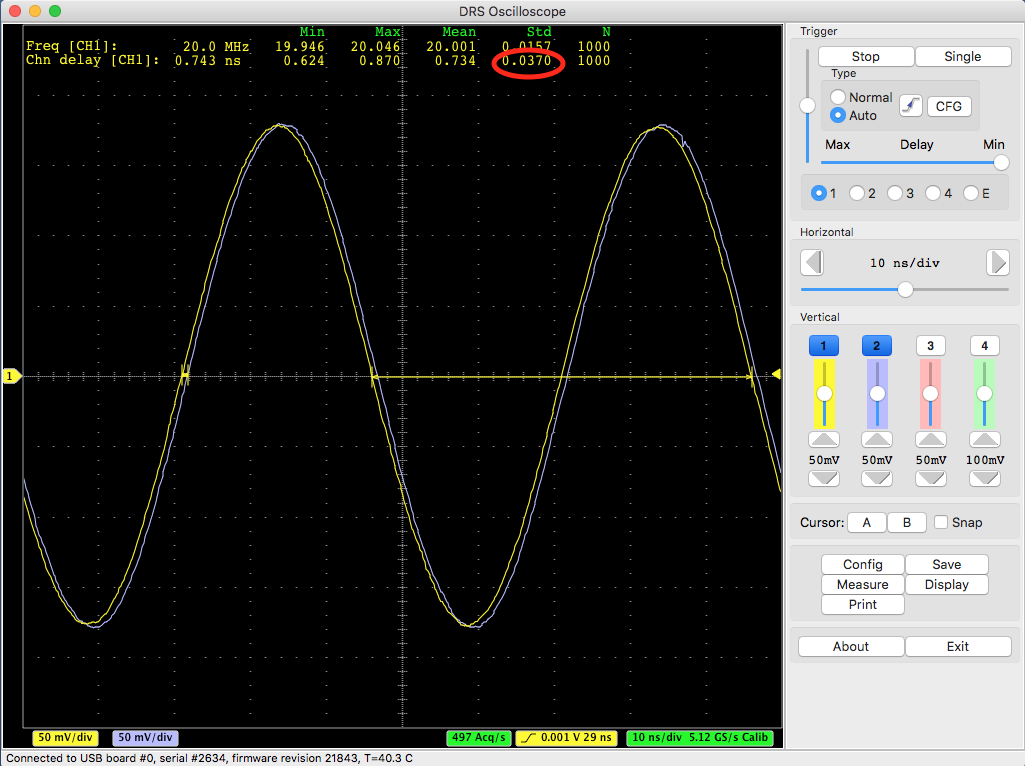
If I increase the frequency to 100 MHz and increase the amplitude, I get a better resolution:
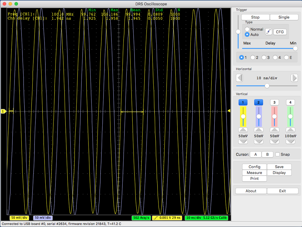
This is 5 ps which is better than 37 ps, but still not 2.5 ps. This can only be reached by sending single pulses to the evaluation board which have a rise time of > 300 mV / ns, which can be seen here:
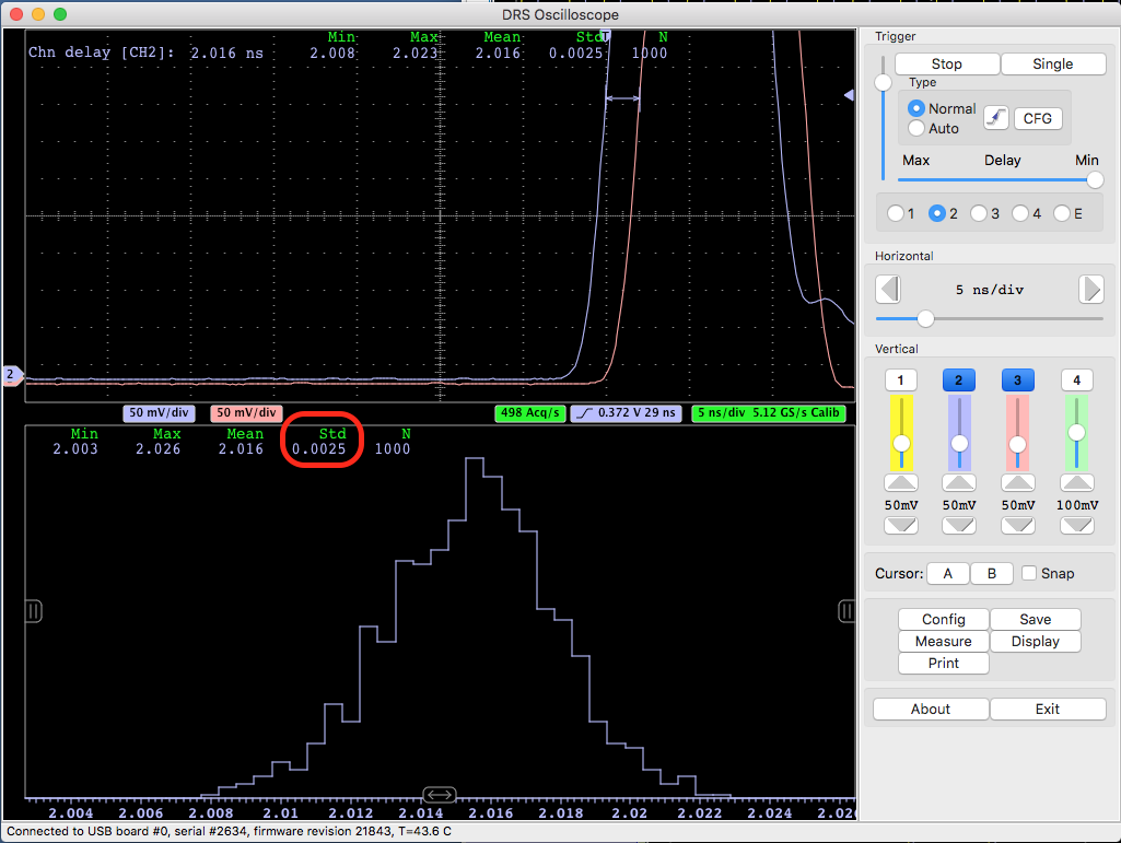
It is important to understand the relation timing - resolution vs. rise time / noise as explained in the quoted paper. If you have tiny pulses from your detector, you never will be able to measure excellent timing. This is physics, and not related to the specific electronics you are using.
Best regards,
Stefan
|
|
|