| ID |
Date |
Author |
Subject |
|
241
|
Mon Apr 22 15:33:28 2013 |
Benjamin LeGeyt | effect of jitter/alignment between SRCLK and ADC clock | Hello!
let me apologize in advance if this has already been covered somewhere and I missed it.
I have a question about a statement made regarding the ADC clock in the evaluation board v4.0 manual. At the bottom or page 23 there is a mention of jitter between the SRCLK signal and the ADC clock causing a baseline variation in the sampled output of up to a few mV. Is there any more information out there about this? I find this confusing for the following reason: If the DRS output has mostly settled after 28ns and the signal that is being sampled is a DC signal, I don't understand why an aperture jitter in the sampling ADC should cause a voltage error in the measured signal. I already know about the possibility of noise spikes every 32 samples if these clocks are not properly aligned, though I don't know the origin of those spikes. are these two things related?
Many Thanks!
|
|
242
|
Mon Apr 22 15:52:53 2013 |
Stefan Ritt | effect of jitter/alignment between SRCLK and ADC clock |
| Benjamin LeGeyt wrote: |
|
Hello!
let me apologize in advance if this has already been covered somewhere and I missed it.
I have a question about a statement made regarding the ADC clock in the evaluation board v4.0 manual. At the bottom or page 23 there is a mention of jitter between the SRCLK signal and the ADC clock causing a baseline variation in the sampled output of up to a few mV. Is there any more information out there about this? I find this confusing for the following reason: If the DRS output has mostly settled after 28ns and the signal that is being sampled is a DC signal, I don't understand why an aperture jitter in the sampling ADC should cause a voltage error in the measured signal. I already know about the possibility of noise spikes every 32 samples if these clocks are not properly aligned, though I don't know the origin of those spikes. are these two things related?
Many Thanks!
|
Hi Benjamin,
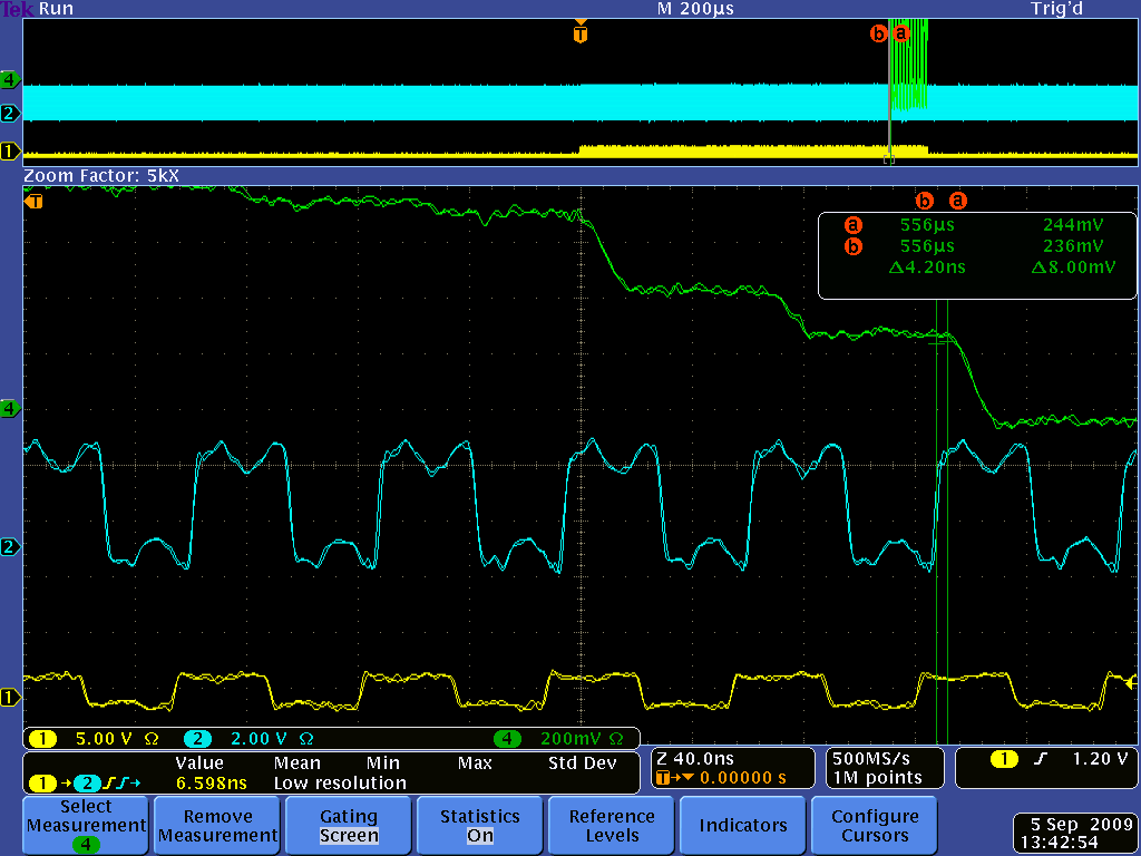
In principle you are right, for a DC signal that should not matter. But in reality the DRS4 output signal is not constant even for a DC signal. When you switch from one sampling cell to another during readout, there is something called "charge injection". This causes the output to change up to several 10 mV. After 28 ns this is mostly settled, but not completely, since the DRS4 output driver has a relatively low bandwidth (~50 MHz). Furthermore, the signal line between the DRS4 and the ADC is not terminated, so you have some reflections going forth and back. In addition, you have some crosstalk from the SRCLK signal. So it's better that you sample on each cycle at exactly the same time. Here you see a plot of that (green: DRS4 output, blue: ADC clock, yellow SRCLK):
|
|
342
|
Tue May 13 19:34:58 2014 |
Luka Pavelic | drsosc binary to cern ROOT file conversion | Hi,
Does anybody have program for conversion from binary or xml to cern ROOT *.root file?
Thank you for any help you can provide,
Luka Pavelic
|
|
343
|
Tue May 13 19:39:36 2014 |
Stefan Ritt | drsosc binary to cern ROOT file conversion |
| Luka Pavelic wrote: |
|
Hi,
Does anybody have program for conversion from binary or xml to cern ROOT *.root file?
Thank you for any help you can provide,
Luka Pavelic
|
You look here: elog:262
/Stefan |
|
344
|
Tue May 13 22:03:47 2014 |
Luka Pavelic | drsosc binary to cern ROOT file conversion | Thank you for your fast and very helpful replay.
I made it work with drsosc version 4 but with version 5 i am getting weird results. Is it possible that they changed binary formatting?
|
|
345
|
Tue May 13 23:08:50 2014 |
Stefan Ritt | drsosc binary to cern ROOT file conversion |
| Luka Pavelic wrote: |
|
Thank you for your fast and very helpful replay.
I made it work with drsosc version 4 but with version 5 i am getting weird results. Is it possible that they changed binary formatting?
|
Yes, but this is documented in the evaluation board manual. You have to modify the script slightly. I will update it myself in about 2-3 weeks.
Cheers,
Stefan |
|
357
|
Fri Jun 27 11:23:19 2014 |
ChengMing Du | drsosc binary to cern ROOT file conversion |
| Stefan Ritt wrote: |
|
| Luka Pavelic wrote: |
|
Thank you for your fast and very helpful replay.
I made it work with drsosc version 4 but with version 5 i am getting weird results. Is it possible that they changed binary formatting?
|
Yes, but this is documented in the evaluation board manual. You have to modify the script slightly. I will update it myself in about 2-3 weeks.
Cheers,
Stefan
|
hi Stefan,can you update the code to convert binary to root for newest drsosc?Thanks. |
|
362
|
Wed Jul 30 17:05:38 2014 |
Stefan Ritt | drsosc binary to cern ROOT file conversion |
| ChengMing Du wrote: |
|
| Stefan Ritt wrote: |
|
| Luka Pavelic wrote: |
|
Thank you for your fast and very helpful replay.
I made it work with drsosc version 4 but with version 5 i am getting weird results. Is it possible that they changed binary formatting?
|
Yes, but this is documented in the evaluation board manual. You have to modify the script slightly. I will update it myself in about 2-3 weeks.
Cheers,
Stefan
|
hi Stefan,can you update the code to convert binary to root for newest drsosc?Thanks.
|
See elog:361 |
|
590
|
Tue Mar 28 21:53:12 2017 |
Jim Freeman | drscl doesn't find eval board but drsosc does (Windows 7) | I cannot find the EVAL board using drscl version 5.06 while the drsosc works fine. I tried 2 different eval boards and 2 different computers and the same effect. I looked under device manager at the libusb and the drs4 was there, and checked the driver which was found to be up to date. |
|
591
|
Wed Apr 5 12:28:28 2017 |
Stefan Ritt | drscl doesn't find eval board but drsosc does (Windows 7) | Two people report now this problem, while this works fine at our lab. So I'm puzzled right now.
I attach two screenshots from the device manager and the Command Line interface. Can you compare it with what you see? Which is the firmware version of your evaluaiton board?
Stefan
| Jim Freeman wrote: |
|
I cannot find the EVAL board using drscl version 5.06 while the drsosc works fine. I tried 2 different eval boards and 2 different computers and the same effect. I looked under device manager at the libusb and the drs4 was there, and checked the driver which was found to be up to date.
|
|
| Attachment 1: Screen_Shot_2017-04-05_at_12.27.46_.png
|

|
| Attachment 2: Screen_Shot_2017-04-05_at_11.45.07_.png
|

|
|
654
|
Thu Jan 25 06:10:52 2018 |
chen wenjun | drscl doesn't find eval board but drsosc does (Windows 7) | Hi! Jim:
It seems that I meet the same question with you ,and I am confused ,have you find out the reason about this problem?Or can you tell me how you deal with it?
Thank you very much!
chen
| Jim Freeman wrote: |
|
I cannot find the EVAL board using drscl version 5.06 while the drsosc works fine. I tried 2 different eval boards and 2 different computers and the same effect. I looked under device manager at the libusb and the drs4 was there, and checked the driver which was found to be up to date.
|
|
|
746
|
Wed Mar 6 10:09:01 2019 |
Willy Chang | drscl "no board found" in some Win7 or Win8.X PCs | Hi all,
When connecting the board and running the Zadig program, some Windows PCs may return "driver installation failed." I coudn't find the solution from their download website. So I started the drscl first. Apparently it shows: Successfully scanned, but no boards found. Therefore I checked the Device Manager. A breakdown warning triangle appears under the serial port...
The possible solution may be found here.
Infact, the WinUsb driver has been in existence in your PC. One can just follow the instructions here:
https://docs.microsoft.com/en-us/windows-hardware/drivers/usbcon/winusb-installation
- Plug in your device to the host system.
- Open Device Manager and locate the device.
- Right-click the device and select Update driver software... from the context menu.
- In the wizard, select Browse my computer for driver software.
- Select Let me pick from a list of device drivers on my computer.
- From the list of device classes, select Universal Serial Bus devices.
- The wizard displays WinUsb Device. Select it to load the driver.
In the wizard, somehow the default setting displays Microsoft Device on the Top of the list and replaced the WinUsb Device. You can easily re-load the WinUsb Device. Just ignore the WARNING from the device manager. The board should work fine now.
Willy |
|
833
|
Thu Sep 16 19:04:06 2021 |
Patrick Moriishi Freeman | drs_exam_multi with non-v4 boards, default configuration | Hello,
I made a modified version drs_exam_multi.cpp, but ran into an issue when running. When I ran it, it only found the two boards with lower serial numbers (2781 and 2879) and complained that the others (2880 and 2881) were not v4. Would there be a simple workaround for this type of thing? Also, would I be able to use the .dat format to keep the file sizes down.
If not, I am curious if there is a way I can at least set a default configuration for the drsosc program. It seems the drsosc.cfg is written when drsosc starts? Does it load the configuration from somewhere else? It would be very helpful to keep the same settings between runs, in particular the trigger delays, levels, trigger mode, and voltage offsets. Maybe I can even do this with just a few of the CLI commands? I know this is for experts only, but I think I would just need a few commands (setTrig, setTrigMode, setTrigDelay, that sort of thing) if they do exist. I would check the help now, but I'm running, and I'm pretty sure I saw some for trigger settings.
Anyhow, any help is appreciated in creating a more repeatable and automated data acquisition. Thanks!
|
|
835
|
Sat Sep 18 15:48:30 2021 |
Stefan Ritt | drs_exam_multi with non-v4 boards, default configuration | Hi,
please note the the evaluation board is what it says, a board to evaluate the chip, and is not meant for a full-blown shiny multi-board DAQ channel, so support for that is kind of limited.
Strange that you only find two out of four boards. What happens if you disconnect the two boards the system finds and then try again? Might be that your USB hub does not have enough power to supply four boards (each taking 2.5W, so you need 10W in total). Unplugging some board will show you if you have a power problem.
The drsosc.cfg stores the current configuration. For this to work, the drsosc program has to have write access to the directory where the drsosc.cfg program is stored, which is usually the directory from where the program is started. Maybe you have to adjust permissions. Yes you have commands to set everything, just look into drs_exam.cpp and you will find most of them.
Best,
Stefan
| Patrick Moriishi Freeman wrote: |
|
Hello,
I made a modified version drs_exam_multi.cpp, but ran into an issue when running. When I ran it, it only found the two boards with lower serial numbers (2781 and 2879) and complained that the others (2880 and 2881) were not v4. Would there be a simple workaround for this type of thing? Also, would I be able to use the .dat format to keep the file sizes down.
If not, I am curious if there is a way I can at least set a default configuration for the drsosc program. It seems the drsosc.cfg is written when drsosc starts? Does it load the configuration from somewhere else? It would be very helpful to keep the same settings between runs, in particular the trigger delays, levels, trigger mode, and voltage offsets. Maybe I can even do this with just a few of the CLI commands? I know this is for experts only, but I think I would just need a few commands (setTrig, setTrigMode, setTrigDelay, that sort of thing) if they do exist. I would check the help now, but I'm running, and I'm pretty sure I saw some for trigger settings.
Anyhow, any help is appreciated in creating a more repeatable and automated data acquisition. Thanks!
|
|
|
914
|
Tue Mar 25 16:31:41 2025 |
Mat�as Tobar | drs_exam.cpp not compile | Hi! i'm trying to compile drs_exam.cpp but it yields the following error lines:
I do have the "DRS.h" file on the same folder, which is clearly the file that's causing troubles. I also tried to run "DRS.cpp" but it yields a similar error lines. ('sin definir' means 'not defined').
Thanks a lot for the help!
$ g++ drs_exam.cpp -o drs_exam
/usr/bin/ld: /tmp/ccroK16H.o: en la función `main':
drs_exam.cpp:(.text+0x48): referencia a `DRS::DRS()' sin definir
/usr/bin/ld: drs_exam.cpp:(.text+0x135): referencia a `DRSBoard::Init()' sin definir
/usr/bin/ld: drs_exam.cpp:(.text+0x155): referencia a `DRSBoard::SetFrequency(double, bool)' sin definir
/usr/bin/ld: drs_exam.cpp:(.text+0x169): referencia a `DRSBoard::SetTranspMode(int)' sin definir
/usr/bin/ld: drs_exam.cpp:(.text+0x184): referencia a `DRSBoard::SetInputRange(double)' sin definir
/usr/bin/ld: drs_exam.cpp:(.text+0x1b6): referencia a `DRSBoard::EnableTrigger(int, int)' sin definir
/usr/bin/ld: drs_exam.cpp:(.text+0x1ca): referencia a `DRSBoard::SetTriggerConfig(int)' sin definir
/usr/bin/ld: drs_exam.cpp:(.text+0x1fe): referencia a `DRSBoard::EnableTrigger(int, int)' sin definir
/usr/bin/ld: drs_exam.cpp:(.text+0x212): referencia a `DRSBoard::SetTriggerConfig(int)' sin definir
/usr/bin/ld: drs_exam.cpp:(.text+0x22d): referencia a `DRSBoard::SetTriggerLevel(double)' sin definir
/usr/bin/ld: drs_exam.cpp:(.text+0x241): referencia a `DRSBoard::SetTriggerPolarity(bool)' sin definir
/usr/bin/ld: drs_exam.cpp:(.text+0x255): referencia a `DRSBoard::SetTriggerDelayNs(int)' sin definir
/usr/bin/ld: drs_exam.cpp:(.text+0x2b6): referencia a `DRSBoard::StartDomino()' sin definir
/usr/bin/ld: drs_exam.cpp:(.text+0x2e9): referencia a `DRSBoard::IsBusy()' sin definir
/usr/bin/ld: drs_exam.cpp:(.text+0x30b): referencia a `DRSBoard::TransferWaves(int, int)' sin definir
/usr/bin/ld: drs_exam.cpp:(.text+0x326): referencia a `DRSBoard::GetTriggerCell(unsigned int)' sin definir
/usr/bin/ld: drs_exam.cpp:(.text+0x350): referencia a `DRSBoard::GetTime(unsigned int, int, int, float*, bool, bool)' sin definir
/usr/bin/ld: drs_exam.cpp:(.text+0x377): referencia a `DRSBoard::GetWave(unsigned int, unsigned char, float*)' sin definir
/usr/bin/ld: drs_exam.cpp:(.text+0x392): referencia a `DRSBoard::GetTriggerCell(unsigned int)' sin definir
/usr/bin/ld: drs_exam.cpp:(.text+0x3c3): referencia a `DRSBoard::GetTime(unsigned int, int, int, float*, bool, bool)' sin definir
/usr/bin/ld: drs_exam.cpp:(.text+0x3f1): referencia a `DRSBoard::GetWave(unsigned int, unsigned char, float*)' sin definir
/usr/bin/ld: drs_exam.cpp:(.text+0x52e): referencia a `DRS::~DRS()' sin definir
collect2: error: ld returned 1 exit status
|
| Attachment 1: DRS.h
|
/********************************************************************
  DRS.h, S.Ritt, M. Schneebeli - PSI

  $Id: DRS.h 21309 2014-04-11 14:51:29Z ritt $

********************************************************************/
#ifndef DRS_H
#define DRS_H
#include <stdio.h>
#include <string.h>
#include "averager.h"

#ifdef HAVE_LIBUSB
#   ifndef HAVE_USB
#      define HAVE_USB
#   endif
#endif

#ifdef HAVE_USB
#   include <musbstd.h>
#endif                          // HAVE_USB

#ifdef HAVE_VME
#   include <mvmestd.h>
#endif                          // HAVE_VME

/* disable "deprecated" warning */
#ifdef _MSC_VER
#pragma warning(disable: 4996)
#endif

#ifndef NULL
#define NULL 0
#endif

int drs_kbhit();
unsigned int millitime();

/* transport mode */
#define TR_VME   1
#define TR_USB   2
#define TR_USB2  3

/* address types */
#ifndef T_CTRL
#define T_CTRL   1
#define T_STATUS 2
#define T_RAM    3
#define T_FIFO   4
#endif

/*---- Register addresses ------------------------------------------*/

#define REG_CTRL                     0x00000    /* 32 bit control reg */
#define REG_DAC_OFS                  0x00004
#define REG_DAC0                     0x00004
#define REG_DAC1                     0x00006
#define REG_DAC2                     0x00008
#define REG_DAC3                     0x0000A
#define REG_DAC4                     0x0000C
#define REG_DAC5                     0x0000E
#define REG_DAC6                     0x00010
#define REG_DAC7                     0x00012
#define REG_CHANNEL_CONFIG           0x00014    // low byte
#define REG_CONFIG                   0x00014    // high byte
#define REG_CHANNEL_MODE             0x00016
#define REG_ADCCLK_PHASE             0x00016
#define REG_FREQ_SET_HI              0x00018    // DRS2
#define REG_FREQ_SET_LO              0x0001A    // DRS2
#define REG_TRG_DELAY                0x00018    // DRS4
#define REG_FREQ_SET                 0x0001A    // DRS4
#define REG_TRIG_DELAY               0x0001C
#define REG_LMK_MSB                  0x0001C    // DRS4 Mezz
#define REG_CALIB_TIMING             0x0001E    // DRS2
#define REG_EEPROM_PAGE_EVAL         0x0001E    // DRS4 Eval
#define REG_EEPROM_PAGE_MEZZ         0x0001A    // DRS4 Mezz
#define REG_TRG_CONFIG               0x0001C    // DRS4 Eval4
#define REG_LMK_LSB                  0x0001E    // DRS4 Mezz
#define REG_READOUT_DELAY            0x00020    // DRS4 Eval5
#define REG_WARMUP                   0x00020    // DRS4 Mezz
#define REG_COOLDOWN                 0x00022    // DRS4 Mezz
#define REG_READ_POINTER             0x00026    // DRS4 Mezz

#define REG_MAGIC                    0x00000
#define REG_BOARD_TYPE               0x00002
#define REG_STATUS                   0x00004
#define REG_RDAC_OFS                 0x0000E
#define REG_RDAC0                    0x00008
#define REG_STOP_CELL0               0x00008
#define REG_RDAC1                    0x0000A
#define REG_STOP_CELL1               0x0000A
#define REG_RDAC2                    0x0000C
#define REG_STOP_CELL2               0x0000C
#define REG_RDAC3                    0x0000E
#define REG_STOP_CELL3               0x0000E
#define REG_RDAC4                    0x00000
#define REG_RDAC5                    0x00002
#define REG_STOP_WSR0                0x00010
#define REG_STOP_WSR1                0x00011
#define REG_STOP_WSR2                0x00012
#define REG_STOP_WSR3                0x00013
#define REG_RDAC6                    0x00014
#define REG_RDAC7                    0x00016
#define REG_EVENTS_IN_FIFO           0x00018
#define REG_EVENT_COUNT              0x0001A
#define REG_FREQ1                    0x0001C
#define REG_FREQ2                    0x0001E
#define REG_WRITE_POINTER            0x0001E
#define REG_TEMPERATURE              0x00020
#define REG_TRIGGER_BUS              0x00022
#define REG_SERIAL_BOARD             0x00024
#define REG_VERSION_FW               0x00026
#define REG_SCALER0                  0x00028
#define REG_SCALER1                  0x0002C
#define REG_SCALER2                  0x00030
#define REG_SCALER3                  0x00034
#define REG_SCALER4                  0x00038
#define REG_SCALER5                  0x0003C

/*---- Control register bit definitions ----------------------------*/

#define BIT_START_TRIG        (1<<0)    // write a "1" to start domino wave
#define BIT_REINIT_TRIG       (1<<1)    // write a "1" to stop & reset DRS
#define BIT_SOFT_TRIG         (1<<2)    // write a "1" to stop and read data to RAM
#define BIT_EEPROM_WRITE_TRIG (1<<3)    // write a "1" to write into serial EEPROM
#define BIT_EEPROM_READ_TRIG  (1<<4)    // write a "1" to read from serial EEPROM
#define BIT_MULTI_BUFFER     (1<<16)    // Use multi buffering when "1"
#define BIT_DMODE            (1<<17)    // (*DRS2*) 0: single shot, 1: circular
#define BIT_ADC_ACTIVE       (1<<17)    // (*DRS4*) 0: stop ADC when running, 1: ADC always clocked
#define BIT_LED              (1<<18)    // 1=on, 0=blink during readout
#define BIT_TCAL_EN          (1<<19)    // switch on (1) / off (0) for 33 MHz calib signal
#define BIT_TCAL_SOURCE      (1<<20)
#define BIT_REFCLK_SOURCE    (1<<20)
#define BIT_FREQ_AUTO_ADJ    (1<<21)    // DRS2/3
#define BIT_TRANSP_MODE      (1<<21)    // DRS4
#define BIT_ENABLE_TRIGGER1  (1<<22)    // External LEMO/FP/TRBUS trigger
#define BIT_LONG_START_PULSE (1<<23)    // (*DRS2*) 0:short start pulse (>0.8GHz), 1:long start pulse (<0.8GHz)
#define BIT_READOUT_MODE     (1<<23)    // (*DRS3*,*DRS4*) 0:start from first bin, 1:start from domino stop
#define BIT_DELAYED_START    (1<<24)    // DRS2: start domino wave 400ns after soft trigger, used for waveform
                                        // generator startup
#define BIT_NEG_TRIGGER      (1<<24)    // DRS4: use high-to-low trigger if set
#define BIT_ACAL_EN          (1<<25)    // connect DRS to inputs (0) or to DAC6 (1)
#define BIT_TRIGGER_DELAYED  (1<<26)    // select delayed trigger from trigger bus
#define BIT_ADCCLK_INVERT    (1<<26)    // invert ADC clock
#define BIT_REFCLK_EXT       (1<<26)    // use external MMCX CLKIN refclk
#define BIT_DACTIVE          (1<<27)    // keep domino wave running during readout
#define BIT_STANDBY_MODE     (1<<28)    // put chip in standby mode
#define BIT_TR_SOURCE1       (1<<29)    // trigger source selection bits
#define BIT_DECIMATION       (1<<29)    // drop all odd samples (DRS4 mezz.)
#define BIT_TR_SOURCE2       (1<<30)    // trigger source selection bits
#define BIT_ENABLE_TRIGGER2  (1<<31)    // analog threshold (internal) trigger

/* DRS4 configuration register bit definitions */
#define BIT_CONFIG_DMODE      (1<<8)    // 0: single shot, 1: circular
#define BIT_CONFIG_PLLEN      (1<<9)    // write a "1" to enable the internal PLL
#define BIT_CONFIG_WSRLOOP   (1<<10)    // write a "1" to connect WSROUT to WSRIN internally

/*---- Status register bit definitions -----------------------------*/

#define BIT_RUNNING           (1<<0)    // one if domino wave running or readout in progress
#define BIT_NEW_FREQ1         (1<<1)    // one if new frequency measurement available
#define BIT_NEW_FREQ2         (1<<2)
#define BIT_PLL_LOCKED0       (1<<1)    // 1 if PLL has locked (DRS4 evaluation board only)
#define BIT_PLL_LOCKED1       (1<<2)    // 1 if PLL DRS4 B has locked (DRS4 mezzanine board only)
#define BIT_PLL_LOCKED2       (1<<3)    // 1 if PLL DRS4 C has locked (DRS4 mezzanine board only)
#define BIT_PLL_LOCKED3       (1<<4)    // 1 if PLL DRS4 D has locked (DRS4 mezzanine board only)
#define BIT_SERIAL_BUSY       (1<<5)    // 1 if EEPROM operation in progress
#define BIT_LMK_LOCKED        (1<<6)    // 1 if PLL of LMK chip has locked (DRS4 mezzanine board only)
#define BIT_2048_MODE         (1<<7)    // 1 if 2048-bin mode has been soldered

enum DRSBoardConstants {
   kNumberOfChannelsMax         =   10,
   kNumberOfCalibChannelsV3     =   10,
   kNumberOfCalibChannelsV4     =    8,
   kNumberOfBins                = 1024,
   kNumberOfChipsMax            =    4,
   kFrequencyCacheSize          =   10,
   kBSplineOrder                =    4,
   kPreCaliculatedBSplines      = 1000,
   kPreCaliculatedBSplineGroups =    5,
   kNumberOfADCBins             = 4096,
   kBSplineXMinOffset           =   20,
   kMaxNumberOfClockCycles      =  100,
};

enum DRSErrorCodes {
   kSuccess                     =  0,
   kInvalidTriggerSignal        = -1,
   kWrongChannelOrChip          = -2,
   kInvalidTransport            = -3,
   kZeroSuppression             = -4,
   kWaveNotAvailable            = -5
};

/*---- callback class ----*/

class DRSCallback
{
public:
   virtual void Progress(int value) = 0;
   virtual ~DRSCallback() {};
};

/*------------------------*/

class DRSBoard;

class ResponseCalibration {
protected:

   class CalibrationData {
   public:
      class CalibrationDataChannel {
      public:
         unsigned char   fLimitGroup[kNumberOfBins];           //!
         float           fMin[kNumberOfBins];                  //!
         float           fRange[kNumberOfBins];                //!
         short           fOffset[kNumberOfBins];               //!
         short           fGain[kNumberOfBins];                 //!
         unsigned short  fOffsetADC[kNumberOfBins];            //!
         short          *fData[kNumberOfBins];                 //!
         unsigned char  *fLookUp[kNumberOfBins];               //!
         unsigned short  fLookUpOffset[kNumberOfBins];         //!
         unsigned char   fNumberOfLookUpPoints[kNumberOfBins]; //!
         float          *fTempData;                            //!

      private:
         CalibrationDataChannel(const CalibrationDataChannel &c);              // not implemented
         CalibrationDataChannel &operator=(const CalibrationDataChannel &rhs); // not implemented

      public:
         CalibrationDataChannel(int numberOfGridPoints)
         :fTempData(new float[numberOfGridPoints]) {
            int i;
            for (i = 0; i < kNumberOfBins; i++) {
               fData[i] = new short[numberOfGridPoints];
            }
            memset(fLimitGroup,           0, sizeof(fLimitGroup));
            memset(fMin,                  0, sizeof(fMin));
            memset(fRange,                0, sizeof(fRange));
            memset(fOffset,               0, sizeof(fOffset));
            memset(fGain,                 0, sizeof(fGain));
            memset(fOffsetADC,            0, sizeof(fOffsetADC));
            memset(fLookUp,               0, sizeof(fLookUp));
            memset(fLookUpOffset,         0, sizeof(fLookUpOffset));
            memset(fNumberOfLookUpPoints, 0, sizeof(fNumberOfLookUpPoints));
         }
         ~CalibrationDataChannel() {
            int i;
            delete fTempData;
            for (i = 0; i < kNumberOfBins; i++) {
               delete fData[i];
               delete fLookUp[i];
            }
         }
      };

      bool                    fRead;                                  //!
      CalibrationDataChannel *fChannel[10];                           //!
      unsigned char           fNumberOfGridPoints;                    //!
      int                     fHasOffsetCalibration;                  //!
      float                   fStartTemperature;                      //!
      float                   fEndTemperature;                        //!
      int                    *fBSplineOffsetLookUp[kNumberOfADCBins]; //!
      float                 **fBSplineLookUp[kNumberOfADCBins];       //!
      float                   fMin;                                   //!
      float                   fMax;                                   //!
      unsigned char           fNumberOfLimitGroups;                   //!
      static float            fIntRevers[2 * kBSplineOrder - 2];

   private:
      CalibrationData(const CalibrationData &c);              // not implemented
      CalibrationData &operator=(const CalibrationData &rhs); // not implemented

   public:
      CalibrationData(int numberOfGridPoints);
      ~CalibrationData();
      static int CalculateBSpline(int nGrid, float value, float *bsplines);
      void       PreCalculateBSpline();
      void       DeletePreCalculatedBSpline();
   };

   // General Fields
   DRSBoard        *fBoard;

   double           fPrecision;

   // Fields for creating the Calibration
   bool             fInitialized;
   bool             fRecorded;
   bool             fFitted;
   bool             fOffset;
   bool             fCalibrationValid[2];

   int              fNumberOfPointsLowVolt;
   int              fNumberOfPoints;
   int              fNumberOfMode2Bins;
   int              fNumberOfSamples;
   int              fNumberOfGridPoints;
   int              fNumberOfXConstPoints;
... 655 more lines ...
|
| Attachment 2: drs_exam.cpp
|
/********************************************************************\

  Name:         drs_exam.cpp
  Created by:   Stefan Ritt

  Contents:     Simple example application to read out a DRS4
                evaluation board

  $Id: drs_exam.cpp 21308 2014-04-11 14:50:16Z ritt $

\********************************************************************/

#include <math.h>

#ifdef _MSC_VER

#include <windows.h>

#elif defined(OS_LINUX)

#define O_BINARY 0

#include <unistd.h>
#include <ctype.h>
#include <sys/ioctl.h>
#include <errno.h>

#define DIR_SEPARATOR '/'

#endif

#include <stdio.h>
#include <string.h>
#include <stdlib.h>

#include "strlcpy.h"
#include "DRS.h"

/*------------------------------------------------------------------*/

int main()
{
   int i, j, nBoards;
   DRS *drs;
   DRSBoard *b;
   float time_array[8][1024];
   float wave_array[8][1024];
   FILE  *f;

   /* do initial scan */
   drs = new DRS();

   /* show any found board(s) */
   for (i=0 ; i<drs->GetNumberOfBoards() ; i++) {
      b = drs->GetBoard(i);
      printf("Found DRS4 evaluation board, serial #%d, firmware revision %d\n",
         b->GetBoardSerialNumber(), b->GetFirmwareVersion());
   }

   /* exit if no board found */
   nBoards = drs->GetNumberOfBoards();
   if (nBoards == 0) {
      printf("No DRS4 evaluation board found\n");
      return 0;
   }

   /* continue working with first board only */
   b = drs->GetBoard(0);

   /* initialize board */
   b->Init();

   /* set sampling frequency */
   b->SetFrequency(5, true);

   /* enable transparent mode needed for analog trigger */
   b->SetTranspMode(1);

   /* set input range to -0.5V ... +0.5V */
   b->SetInputRange(0);

   /* use following line to set range to 0..1V */
   //b->SetInputRange(0.5);

   /* use following line to turn on the internal 100 MHz clock connected to all channels  */
   //b->EnableTcal(1);

   /* use following lines to enable hardware trigger on CH1 at 50 mV positive edge */
   if (b->GetBoardType() >= 8) {        // Evaluaiton Board V4&5
      b->EnableTrigger(1, 0);           // enable hardware trigger
      b->SetTriggerConfig(1<<0);        // set CH1 as source
   } else if (b->GetBoardType() == 7) { // Evaluation Board V3
      b->EnableTrigger(0, 1);           // lemo off, analog trigger on
      b->SetTriggerConfig(1);           // use CH1 as source
   }
   b->SetTriggerLevel(0.05);            // 0.05 V
   b->SetTriggerPolarity(false);        // positive edge

   /* use following lines to set individual trigger elvels */
   //b->SetIndividualTriggerLevel(1, 0.1);
   //b->SetIndividualTriggerLevel(2, 0.2);
   //b->SetIndividualTriggerLevel(3, 0.3);
   //b->SetIndividualTriggerLevel(4, 0.4);
   //b->SetTriggerSource(15);

   b->SetTriggerDelayNs(0);             // zero ns trigger delay

   /* use following lines to enable the external trigger */
   //if (b->GetBoardType() >= 8) {        // Evaluaiton Board V4&5
   //   b->EnableTrigger(1, 0);           // enable hardware trigger
   //   b->SetTriggerConfig(1<<4);        // set external trigger as source
   //} else {                             // Evaluation Board V3
   //   b->EnableTrigger(1, 0);           // lemo on, analog trigger off
   //}

   /* open file to save waveforms */
   f = fopen("data.txt", "w");
   if (f == NULL) {
      perror("ERROR: Cannot open file \"data.txt\"");
      return 1;
   }

   /* repeat ten times */
   for (j=0 ; j<10 ; j++) {

      /* start board (activate domino wave) */
      b->StartDomino();

      /* wait for trigger */
      printf("Waiting for trigger...");

      fflush(stdout);
      while (b->IsBusy());

      /* read all waveforms */
      b->TransferWaves(0, 8);

      /* read time (X) array of first channel in ns */
      b->GetTime(0, 0, b->GetTriggerCell(0), time_array[0]);

      /* decode waveform (Y) array of first channel in mV */
      b->GetWave(0, 0, wave_array[0]);

      /* read time (X) array of second channel in ns
       Note: On the evaluation board input #1 is connected to channel 0 and 1 of
       the DRS chip, input #2 is connected to channel 2 and 3 and so on. So to
       get the input #2 we have to read DRS channel #2, not #1. */
      b->GetTime(0, 2, b->GetTriggerCell(0), time_array[1]);

      /* decode waveform (Y) array of second channel in mV */
      b->GetWave(0, 2, wave_array[1]);

      /* Save waveform: X=time_array[i], Yn=wave_array[n][i] */
      fprintf(f, "Event #%d ----------------------\n  t1[ns]  u1[mV]  t2[ns] u2[mV]\n", j);
      for (i=0 ; i<1024 ; i++)
         fprintf(f, "%7.3f %7.1f %7.3f %7.1f\n", time_array[0][i], wave_array[0][i], time_array[1][i], wave_array[1][i]);

      /* print some progress indication */
      printf("\rEvent #%d read successfully\n", j);
   }

   fclose(f);

   /* delete DRS object -> close USB connection */
   delete drs;
}
|
|
915
|
Wed Mar 26 08:42:08 2025 |
Stefan Ritt | drs_exam.cpp not compile | You have to link against the DRS.cpp library, plus usblib, plus ... Note there is both a Makefile and a CMakeLists.txt for it. Google how to use "make" or "cmake".
Stefan |
|
917
|
Tue Apr 1 16:24:33 2025 |
Mat�as Tobar | drs_exam.cpp not compile | Thanks! I solved it by running ./drs_exam after execute Makefile (there was an inconsistency in the files directory).
Matías
| Stefan Ritt wrote: |
|
You have to link against the DRS.cpp library, plus usblib, plus ... Note there is both a Makefile and a CMakeLists.txt for it. Google how to use "make" or "cmake".
Stefan
|
|
|
142
|
Thu Jan 19 23:26:26 2012 |
Heejong Kim | drs_exam.cpp for evaluation board version 4 | Hello,
I'm using DRS4 evaluation board version4 in Linux (Scientific Linux 5).
Version4 software (drs-4.0.0) was installed without any troubles.
The oscilloscope interfrace program (drsosc) is working fine with version4 software.
But when I tried drs_exam program, it doesn't work as expected.
(500 mV positive (width 50ns) pulse is connected to Ch#1).
It keeps waiting trigger in the first event.
In the previous version (board/software drs-3.0.0), drs_exam program worked well.
I'm wondering if anybody is using drs_exam with V4 evaluation board.
Any comments/help would be welcomed.
Thanks,
Heejong |
|
143
|
Fri Jan 20 08:09:38 2012 |
Stefan Ritt | drs_exam.cpp for evaluation board version 4 |
| Heejong Kim wrote: |
|
Hello,
I'm using DRS4 evaluation board version4 in Linux (Scientific Linux 5).
Version4 software (drs-4.0.0) was installed without any troubles.
The oscilloscope interfrace program (drsosc) is working fine with version4 software.
But when I tried drs_exam program, it doesn't work as expected.
(500 mV positive (width 50ns) pulse is connected to Ch#1).
It keeps waiting trigger in the first event.
In the previous version (board/software drs-3.0.0), drs_exam program worked well.
I'm wondering if anybody is using drs_exam with V4 evaluation board.
|
The issue is that the V4 board has new trigger capabilities (such as coincidences between two channels) which require a slightly different configuration. Here it the new code:
/* use following lines to enable hardware trigger on CH1 at 50 mV positive edge */
if (b->GetBoardType() == 8) { // Evaluaiton Board V4
b->EnableTrigger(1, 0); // enable hardware trigger
b->SetTriggerSource(1<<0); // set CH1 as source
} else { // Evaluation Board V3
b->EnableTrigger(0, 1); // lemo off, analog trigger on
b->SetTriggerSource(0); // use CH1 as source
}
The complete file is attached. Please try again with the new code. Probably next week I will make a new software release (including a Mac version of all programs) which will contain the new code. Sorry for any inconvenience.
Best regards,
Stefan
|
| Attachment 1: drs_exam.cpp
|
/********************************************************************\

  Name:         drs_exam.cpp
  Created by:   Stefan Ritt

  Contents:     Simple example application to read out a DRS4
                evaluation board

  $Id: drs_exam.cpp 18834 2012-01-05 12:38:20Z ritt $

\********************************************************************/

#include <math.h>

#ifdef _MSC_VER

#include <windows.h>

#elif defined(OS_LINUX)

#define O_BINARY 0

#include <unistd.h>
#include <ctype.h>
#include <sys/ioctl.h>
#include <errno.h>

#define DIR_SEPARATOR '/'

#endif

#include <stdio.h>
#include <string.h>
#include <stdlib.h>

#include "strlcpy.h"
#include "DRS.h"

/*------------------------------------------------------------------*/

int main()
{
   int i, j, nBoards;
   DRS *drs;
   DRSBoard *b;
   float time_array[1024];
   float wave_array[8][1024];
   FILE  *f;

   /* do initial scan */
   drs = new DRS();

   /* show any found board(s) */
   for (i=0 ; i<drs->GetNumberOfBoards() ; i++) {
      b = drs->GetBoard(i);
      printf("Found DRS4 evaluation board, serial #%d, firmware revision %d\n",
         b->GetBoardSerialNumber(), b->GetFirmwareVersion());
   }

   /* exit if no board found */
   nBoards = drs->GetNumberOfBoards();
   if (nBoards == 0) {
      printf("No DRS4 evaluation board found\n");
      return 0;
   }

   /* continue working with first board only */
   b = drs->GetBoard(0);

   /* initialize board */
   b->Init();

   /* set sampling frequency */
   b->SetFrequency(5, true);

   /* enable transparent mode needed for analog trigger */
   b->SetTranspMode(1);

   /* set input range to -0.5V ... +0.5V */
   b->SetInputRange(0);

   /* use following line to set range to 0..1V */
   //b->SetInputRange(0.5);

   /* use following lines to enable hardware trigger on CH1 at 50 mV positive edge */
   if (b->GetBoardType() == 8) {     // Evaluaiton Board V4
      b->EnableTrigger(1, 0);           // enable hardware trigger
      b->SetTriggerSource(1<<0);        // set CH1 as source
   } else {                          // Evaluation Board V3
      b->EnableTrigger(0, 1);           // lemo off, analog trigger on
      b->SetTriggerSource(0);           // use CH1 as source
   }
   b->SetTriggerLevel(0.05, false);     // 0.05 V, positive edge
   b->SetTriggerDelayNs(0);             // zero ns trigger delay

   /* open file to save waveforms */
   f = fopen("data.txt", "w");
   if (f == NULL) {
      perror("ERROR: Cannot open file \"data.txt\"");
      return 1;
   }

   /* repeat ten times */
   for (j=0 ; j<10 ; j++) {

      /* start board (activate domino wave) */
      b->StartDomino();

      /* wait for trigger */
      printf("Waiting for trigger...");
      fflush(stdout);
      while (b->IsBusy());

      /* read all waveforms */
      b->TransferWaves(0, 8);

      /* read time (X) array in ns */
      b->GetTime(0, b->GetTriggerCell(0), time_array);

      /* decode waveform (Y) array first channel in mV */
      b->GetWave(0, 0, wave_array[0]);

      /* decode waveform (Y) array second channel in mV
         Note: On the evaluation board input #1 is connected to channel 0 and 1 of
         the DRS chip, input #2 is connected to channel 2 and 3 and so on. So to
         get the input #2 we have to read DRS channel #2, not #1 */
      b->GetWave(0, 2, wave_array[1]);

      /* Save waveform: X=time_array[i], Yn=wave_array[n][i] */
      fprintf(f, "Event #%d: t y1 y2\n", j);
      for (i=0 ; i<1024 ; i++)
         //fprintf(f, "%1.2f %1.2f %1.2f\n", time_array[i], wave_array[0][i], wave_array[1][i]);
         fprintf(f, "%5.2f %6.2f\n", time_array[i], wave_array[0][i]);

      /* print some progress indication */
      printf("\rEvent #%d read successfully\n", j);
   }

   fclose(f);

   /* delete DRS object -> close USB connection */
   delete drs;
}
|
|
144
|
Fri Jan 20 23:50:39 2012 |
Heejong Kim | drs_exam.cpp for evaluation board version 4 |
| Stefan Ritt wrote: |
|
| Heejong Kim wrote: |
|
Hello,
I'm using DRS4 evaluation board version4 in Linux (Scientific Linux 5).
Version4 software (drs-4.0.0) was installed without any troubles.
The oscilloscope interfrace program (drsosc) is working fine with version4 software.
But when I tried drs_exam program, it doesn't work as expected.
(500 mV positive (width 50ns) pulse is connected to Ch#1).
It keeps waiting trigger in the first event.
In the previous version (board/software drs-3.0.0), drs_exam program worked well.
I'm wondering if anybody is using drs_exam with V4 evaluation board.
|
The issue is that the V4 board has new trigger capabilities (such as coincidences between two channels) which require a slightly different configuration. Here it the new code:
/* use following lines to enable hardware trigger on CH1 at 50 mV positive edge */
if (b->GetBoardType() == 8) { // Evaluaiton Board V4
b->EnableTrigger(1, 0); // enable hardware trigger
b->SetTriggerSource(1<<0); // set CH1 as source
} else { // Evaluation Board V3
b->EnableTrigger(0, 1); // lemo off, analog trigger on
b->SetTriggerSource(0); // use CH1 as source
}
The complete file is attached. Please try again with the new code. Probably next week I will make a new software release (including a Mac version of all programs) which will contain the new code. Sorry for any inconvenience.
Best regards,
Stefan
|
Hello Stefan,
Thanks for your prompt reply.
drs_exam is working now after modification as above.
By some trials, I found that external trigger is possible by 'b->EnableTrigger(1,0); b->SetTriggerSource(1<<4);'
Best,
Heejong
|
|