| ID |
Date |
Author |
Subject |
|
470
|
Tue Jan 12 16:06:07 2016 |
Stefan Ritt | Use of Channel Cascading in drs_exam.cpp | Hi Larry,
sorry my late reply, swamped with work here. You were right in the modifictions you did, congrats. The speed limitation of 500 events come from USB2, which simply is not fast enough. The 500 Hz are mentioned on the evaluation board web site, so you should have seen that before ordering. Some people build their own hardware around the chip, in which case they get higher rates. The "hard" limit is the DRS4 readout speed, which is 30ns per sample. So if you have 8 ADCs in parallel, and you only need 100 samples of your waveform, the readout time is 3 us, in which case you could go up to a few 10 kHz without much of a dead time.
Cheers,
Stefan
| Larry Byars wrote: |
|
An update. I have been successful in making modifications to drs_exam.cpp so that I can get 2048 samples per channel.. The main changes were to the size of the time_array and wave_array and adding a call to Set ChannelConfig(0,8,4). It was also necessary to change the parameters to GetWave so that the Trigger Cell and WSR values were passed to get the channel combinations correct (2048 channel.ppt).
I've moved on to try to increase the speed of acquisition (I get only about 500 events/sec) and trying to understand the corrections.Working through the source code slowly...
Regards,
Larry Byars
| Larry Byars wrote: |
|
Hello Stefan,
Here in Rockford, TN we just got a new DRS4 evaluation board (Serail # 2612, Board Type 9, Firmware 21305) which is labeled as combined 2048.
It looks like the drs_exam.cpp only works with 1024 samples per channel. We'd like to be able to get 2048 samples from each of the four channels but I am uncertain what code modifications are necessary support this.
Could you offer a suggestion? I've searched the forum for cascade and read several threads but they are pretty old. One even says it isn't supported in the evaluation board, but I think that is no longer the case.
Thanks for your help,
Larry Byars
|
|
|
|
820
|
Wed Apr 7 03:29:39 2021 |
Sean Quinn | Unexpected noise in muxout: t_samp related? | Dear DRS4 team,
I'm experiencing some issues that seem to be isolated to the ASIC, and would like to understand if we are doing something wrong. There are several items to address in the post.
First, I do not think the noise observed is being injected from elsewhere on the board. If I run the DRS in transparent mode, the baseline noise is low, on order 3.5 mV (60 ADU), perhaps radiated from a clock. See below image. The scale is 0 to 1000 ADU with LSB = 6 uV (same AD9245 as eval board.). The DRS is in RUNNING state, I have forced a trigger in the ILA. This is for a single channel, CH0, 1024 cells.
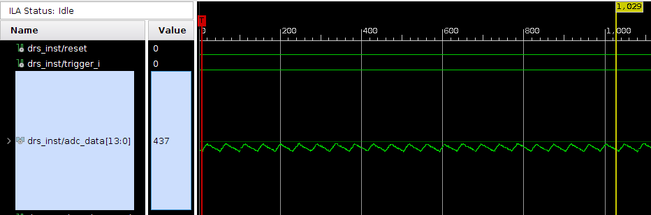
In the next image, I show the waveform obtained from a full readout. This corresponds to ADC_READOUT state, and the plot uses the same 1000 ADU scale. Noise seems around 350 ADU now, many factors worse than before.
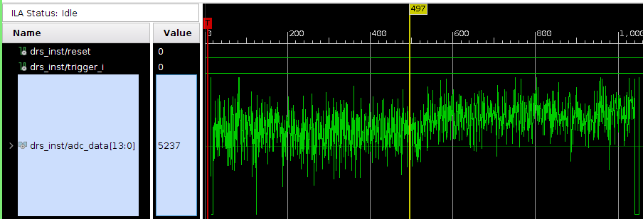
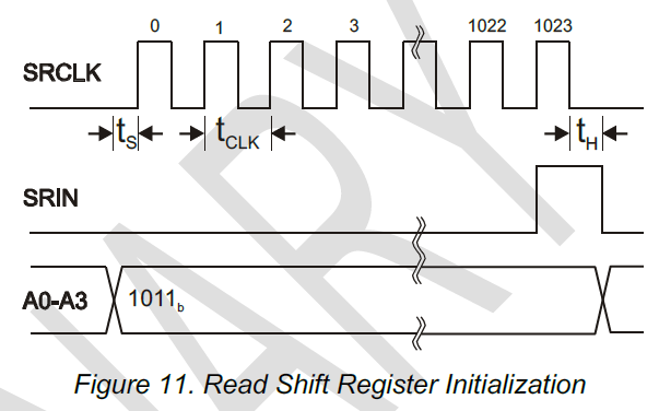
We've spent a lot of time trying to understand what's happening. One area that would be helpful to get some guidance on is the "t_samp" parameter. In Fig. 11 of the data sheet, should there be a t_samp label between t_s and t_clk? It just has arrows there with some width.
In our current firmware I believe R1 is simply one clock after R0 (for both ROI and full readout mode). Would this lead to the added noise observed in muxout?
This leads to the next question on what to actually use for t_samp. In the data sheet, page 4 "Timing Characteristics" it says to use t_samp = t0 + t_clk. Additionally, t0= 10 ns from that table. Fair enough.
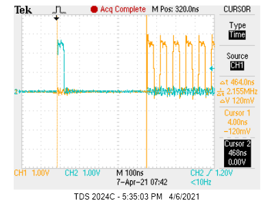
But if I check this against the eval board timing, I see very different values. Here the clock is 15 MHz so t_clk=67 ns (I note another post about this topic https://elog.psi.ch/elogs/DRS4+Forum/713), so I expect t_samp = 77 ns. But in practice it looks like the R0 to R1 delay is ~465 ns? (cyan=RSRLOAD, yellow=SRCLK)
Given this, is t_samp a value that should be tuned by the user?
Best regards,
Sean
|
|
821
|
Wed Apr 7 08:26:12 2021 |
Stefan Ritt | Unexpected noise in muxout: t_samp related? | Dear Sean,
noise in transparent mode comes from some coupling to your system clock. But 3.5 mV RMS seems rather hight to me. You should get it to below 1 mV if the DRS4 input is clean (try to short it).
The noise in the readout is expected. It looks exactly as Plot3 from the data sheet. You have to calibrate it away with a fixed offset for each cell as described in this paper: https://arxiv.org/abs/1405.4975 (paragraph IV. A. Voltage Calibration).
Concerning t_samp: Fig 11 in the datasheet just tells you that the rising edge of the SRCLK should come later than t_s after the address change. t_s is the setup time and 5 ns. Fig 12 tells you that the ADC should sample the analog output of the DRS t_samp after the address change A0-A3 and t_samp after the rising edge of SRCLK.
The digitizing speed of the evaluation board is indeed 15 MHz instead of the maximum 30 MHz, because this was easier to program in the FPGA. The t_samp has to be there so that the analog output signal of the DRS4 settles to its final value after each SRCLK pulse. If you sample "too early", you sample with the ADC the output when it is sill moving. So you have to wait until the analog is settled, but just before the next DRS sample becomes visible at the output. You can fine tune this with a differential probe at the DRS4 analog output (on a single ended probe you might drown in noise) on one channel of yoru scope and the ADC sample clock on the other channel of your scope. Note that the ADC sample clock cannot be derived straight from your FPGA clock, but you need some clock manager to fine-adjust its phase in 1ns steps.
But again, looking at your output, everything seems fine. You see the 5mV rms noise indicated in the datasheet table 1, which translates to about 20 mV peak-to-peak. If you do the offset calibration, this should go down to below 1 mV.
Best,
Stefan
| Sean Quinn wrote: |
|
Dear DRS4 team,
I'm experiencing some issues that seem to be isolated to the ASIC, and would like to understand if we are doing something wrong. There are several items to address in the post.
First, I do not think the noise observed is being injected from elsewhere on the board. If I run the DRS in transparent mode, the baseline noise is low, on order 3.5 mV (60 ADU), perhaps radiated from a clock. See below image. The scale is 0 to 1000 ADU with LSB = 6 uV (same AD9245 as eval board.). The DRS is in RUNNING state, I have forced a trigger in the ILA. This is for a single channel, CH0, 1024 cells.
In the next image, I show the waveform obtained from a full readout. This corresponds to ADC_READOUT state, and the plot uses the same 1000 ADU scale. Noise seems around 350 ADU now, many factors worse than before.
We've spent a lot of time trying to understand what's happening. One area that would be helpful to get some guidance on is the "t_samp" parameter. In Fig. 11 of the data sheet, should there be a t_samp label between t_s and t_clk? It just has arrows there with some width.
In our current firmware I believe R1 is simply one clock after R0 (for both ROI and full readout mode). Would this lead to the added noise observed in muxout?
This leads to the next question on what to actually use for t_samp. In the data sheet, page 4 "Timing Characteristics" it says to use t_samp = t0 + t_clk. Additionally, t0= 10 ns from that table. Fair enough.
But if I check this against the eval board timing, I see very different values. Here the clock is 15 MHz so t_clk=67 ns (I note another post about this topic https://elog.psi.ch/elogs/DRS4+Forum/713), so I expect t_samp = 77 ns. But in practice it looks like the R0 to R1 delay is ~465 ns? (cyan=RSRLOAD, yellow=SRCLK)
Given this, is t_samp a value that should be tuned by the user?
Best regards,
Sean
|
|
|
822
|
Fri Apr 9 20:22:13 2021 |
Sean Quinn | Unexpected noise in muxout: t_samp related? | Hi Stefan,
Thanks much for the quick reply. Ok, yes, things do seem ok after the offset calibration. I am running into some other issues I could use your advice on but will make a separate thread. As a preview, you can see hints in this waveform (periodic negative spikes).
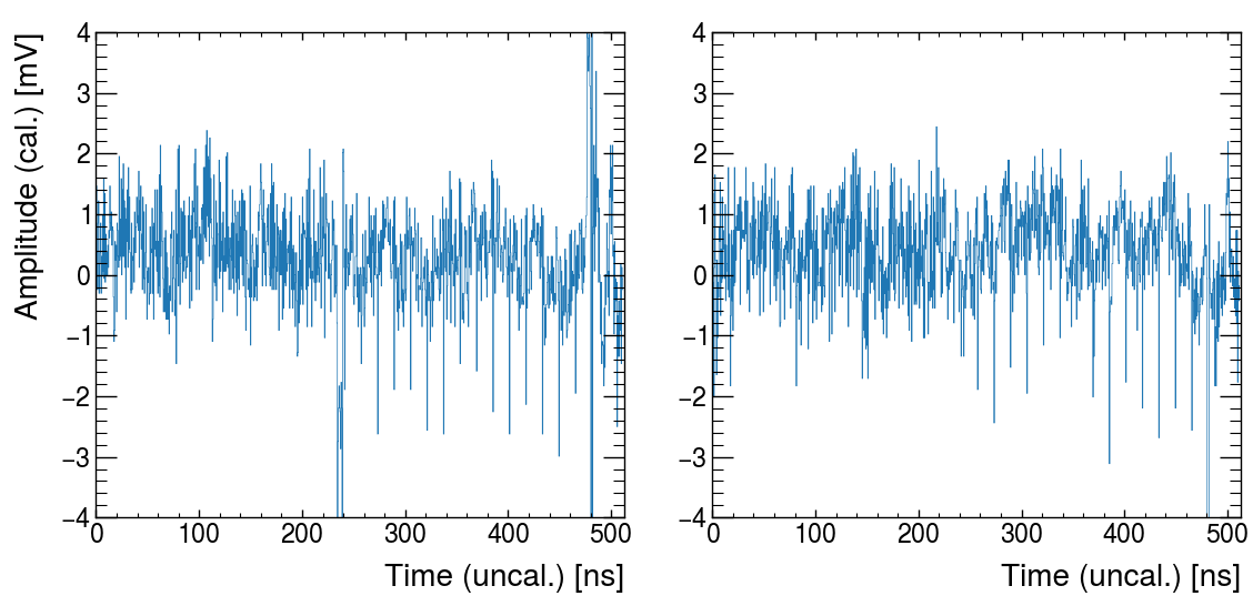
This one should be considered resolved.
| Stefan Ritt wrote: |
|
Dear Sean,
noise in transparent mode comes from some coupling to your system clock. But 3.5 mV RMS seems rather hight to me. You should get it to below 1 mV if the DRS4 input is clean (try to short it).
The noise in the readout is expected. It looks exactly as Plot3 from the data sheet. You have to calibrate it away with a fixed offset for each cell as described in this paper: https://arxiv.org/abs/1405.4975 (paragraph IV. A. Voltage Calibration).
Concerning t_samp: Fig 11 in the datasheet just tells you that the rising edge of the SRCLK should come later than t_s after the address change. t_s is the setup time and 5 ns. Fig 12 tells you that the ADC should sample the analog output of the DRS t_samp after the address change A0-A3 and t_samp after the rising edge of SRCLK.
The digitizing speed of the evaluation board is indeed 15 MHz instead of the maximum 30 MHz, because this was easier to program in the FPGA. The t_samp has to be there so that the analog output signal of the DRS4 settles to its final value after each SRCLK pulse. If you sample "too early", you sample with the ADC the output when it is sill moving. So you have to wait until the analog is settled, but just before the next DRS sample becomes visible at the output. You can fine tune this with a differential probe at the DRS4 analog output (on a single ended probe you might drown in noise) on one channel of yoru scope and the ADC sample clock on the other channel of your scope. Note that the ADC sample clock cannot be derived straight from your FPGA clock, but you need some clock manager to fine-adjust its phase in 1ns steps.
But again, looking at your output, everything seems fine. You see the 5mV rms noise indicated in the datasheet table 1, which translates to about 20 mV peak-to-peak. If you do the offset calibration, this should go down to below 1 mV.
Best,
Stefan
| Sean Quinn wrote: |
|
Dear DRS4 team,
I'm experiencing some issues that seem to be isolated to the ASIC, and would like to understand if we are doing something wrong. There are several items to address in the post.
First, I do not think the noise observed is being injected from elsewhere on the board. If I run the DRS in transparent mode, the baseline noise is low, on order 3.5 mV (60 ADU), perhaps radiated from a clock. See below image. The scale is 0 to 1000 ADU with LSB = 6 uV (same AD9245 as eval board.). The DRS is in RUNNING state, I have forced a trigger in the ILA. This is for a single channel, CH0, 1024 cells.
In the next image, I show the waveform obtained from a full readout. This corresponds to ADC_READOUT state, and the plot uses the same 1000 ADU scale. Noise seems around 350 ADU now, many factors worse than before.
We've spent a lot of time trying to understand what's happening. One area that would be helpful to get some guidance on is the "t_samp" parameter. In Fig. 11 of the data sheet, should there be a t_samp label between t_s and t_clk? It just has arrows there with some width.
In our current firmware I believe R1 is simply one clock after R0 (for both ROI and full readout mode). Would this lead to the added noise observed in muxout?
This leads to the next question on what to actually use for t_samp. In the data sheet, page 4 "Timing Characteristics" it says to use t_samp = t0 + t_clk. Additionally, t0= 10 ns from that table. Fair enough.
But if I check this against the eval board timing, I see very different values. Here the clock is 15 MHz so t_clk=67 ns (I note another post about this topic https://elog.psi.ch/elogs/DRS4+Forum/713), so I expect t_samp = 77 ns. But in practice it looks like the R0 to R1 delay is ~465 ns? (cyan=RSRLOAD, yellow=SRCLK)
Given this, is t_samp a value that should be tuned by the user?
Best regards,
Sean
|
|
|
|
824
|
Fri Apr 9 20:55:28 2021 |
Stefan Ritt | Unexpected noise in muxout: t_samp related? | If you do the cell calibration correctly, your noise should be ~0.4 mV. You seem to be 2-3x larger. The periodic negative spikes come if you dont' sample at the right time. Adjust t_samp until they are gone.
Stefan
| Sean Quinn wrote: |
|
Hi Stefan,
Thanks much for the quick reply. Ok, yes, things do seem ok after the offset calibration. I am running into some other issues I could use your advice on but will make a separate thread. As a preview, you can see hints in this waveform (periodic negative spikes).
This one should be considered resolved.
| Stefan Ritt wrote: |
|
Dear Sean,
noise in transparent mode comes from some coupling to your system clock. But 3.5 mV RMS seems rather hight to me. You should get it to below 1 mV if the DRS4 input is clean (try to short it).
The noise in the readout is expected. It looks exactly as Plot3 from the data sheet. You have to calibrate it away with a fixed offset for each cell as described in this paper: https://arxiv.org/abs/1405.4975 (paragraph IV. A. Voltage Calibration).
Concerning t_samp: Fig 11 in the datasheet just tells you that the rising edge of the SRCLK should come later than t_s after the address change. t_s is the setup time and 5 ns. Fig 12 tells you that the ADC should sample the analog output of the DRS t_samp after the address change A0-A3 and t_samp after the rising edge of SRCLK.
The digitizing speed of the evaluation board is indeed 15 MHz instead of the maximum 30 MHz, because this was easier to program in the FPGA. The t_samp has to be there so that the analog output signal of the DRS4 settles to its final value after each SRCLK pulse. If you sample "too early", you sample with the ADC the output when it is sill moving. So you have to wait until the analog is settled, but just before the next DRS sample becomes visible at the output. You can fine tune this with a differential probe at the DRS4 analog output (on a single ended probe you might drown in noise) on one channel of yoru scope and the ADC sample clock on the other channel of your scope. Note that the ADC sample clock cannot be derived straight from your FPGA clock, but you need some clock manager to fine-adjust its phase in 1ns steps.
But again, looking at your output, everything seems fine. You see the 5mV rms noise indicated in the datasheet table 1, which translates to about 20 mV peak-to-peak. If you do the offset calibration, this should go down to below 1 mV.
Best,
Stefan
| Sean Quinn wrote: |
|
Dear DRS4 team,
I'm experiencing some issues that seem to be isolated to the ASIC, and would like to understand if we are doing something wrong. There are several items to address in the post.
First, I do not think the noise observed is being injected from elsewhere on the board. If I run the DRS in transparent mode, the baseline noise is low, on order 3.5 mV (60 ADU), perhaps radiated from a clock. See below image. The scale is 0 to 1000 ADU with LSB = 6 uV (same AD9245 as eval board.). The DRS is in RUNNING state, I have forced a trigger in the ILA. This is for a single channel, CH0, 1024 cells.
In the next image, I show the waveform obtained from a full readout. This corresponds to ADC_READOUT state, and the plot uses the same 1000 ADU scale. Noise seems around 350 ADU now, many factors worse than before.
We've spent a lot of time trying to understand what's happening. One area that would be helpful to get some guidance on is the "t_samp" parameter. In Fig. 11 of the data sheet, should there be a t_samp label between t_s and t_clk? It just has arrows there with some width.
In our current firmware I believe R1 is simply one clock after R0 (for both ROI and full readout mode). Would this lead to the added noise observed in muxout?
This leads to the next question on what to actually use for t_samp. In the data sheet, page 4 "Timing Characteristics" it says to use t_samp = t0 + t_clk. Additionally, t0= 10 ns from that table. Fair enough.
But if I check this against the eval board timing, I see very different values. Here the clock is 15 MHz so t_clk=67 ns (I note another post about this topic https://elog.psi.ch/elogs/DRS4+Forum/713), so I expect t_samp = 77 ns. But in practice it looks like the R0 to R1 delay is ~465 ns? (cyan=RSRLOAD, yellow=SRCLK)
Given this, is t_samp a value that should be tuned by the user?
Best regards,
Sean
|
|
|
|
|
826
|
Fri Apr 9 21:56:54 2021 |
Sean Quinn | Unexpected noise in muxout: t_samp related? | Yes, there is some systematic board noise on this prototype, unfortunately 
Ok, then it seems the other post I made might still belong in this thread after all.
Thanks for confirming negative spike behavior, we now have a mitigation plan going forward.
Cheers,
| Stefan Ritt wrote: |
|
If you do the cell calibration correctly, your noise should be ~0.4 mV. You seem to be 2-3x larger. The periodic negative spikes come if you dont' sample at the right time. Adjust t_samp until they are gone.
Stefan
| Sean Quinn wrote: |
|
Hi Stefan,
Thanks much for the quick reply. Ok, yes, things do seem ok after the offset calibration. I am running into some other issues I could use your advice on but will make a separate thread. As a preview, you can see hints in this waveform (periodic negative spikes).
This one should be considered resolved.
| Stefan Ritt wrote: |
|
Dear Sean,
noise in transparent mode comes from some coupling to your system clock. But 3.5 mV RMS seems rather hight to me. You should get it to below 1 mV if the DRS4 input is clean (try to short it).
The noise in the readout is expected. It looks exactly as Plot3 from the data sheet. You have to calibrate it away with a fixed offset for each cell as described in this paper: https://arxiv.org/abs/1405.4975 (paragraph IV. A. Voltage Calibration).
Concerning t_samp: Fig 11 in the datasheet just tells you that the rising edge of the SRCLK should come later than t_s after the address change. t_s is the setup time and 5 ns. Fig 12 tells you that the ADC should sample the analog output of the DRS t_samp after the address change A0-A3 and t_samp after the rising edge of SRCLK.
The digitizing speed of the evaluation board is indeed 15 MHz instead of the maximum 30 MHz, because this was easier to program in the FPGA. The t_samp has to be there so that the analog output signal of the DRS4 settles to its final value after each SRCLK pulse. If you sample "too early", you sample with the ADC the output when it is sill moving. So you have to wait until the analog is settled, but just before the next DRS sample becomes visible at the output. You can fine tune this with a differential probe at the DRS4 analog output (on a single ended probe you might drown in noise) on one channel of yoru scope and the ADC sample clock on the other channel of your scope. Note that the ADC sample clock cannot be derived straight from your FPGA clock, but you need some clock manager to fine-adjust its phase in 1ns steps.
But again, looking at your output, everything seems fine. You see the 5mV rms noise indicated in the datasheet table 1, which translates to about 20 mV peak-to-peak. If you do the offset calibration, this should go down to below 1 mV.
Best,
Stefan
| Sean Quinn wrote: |
|
Dear DRS4 team,
I'm experiencing some issues that seem to be isolated to the ASIC, and would like to understand if we are doing something wrong. There are several items to address in the post.
First, I do not think the noise observed is being injected from elsewhere on the board. If I run the DRS in transparent mode, the baseline noise is low, on order 3.5 mV (60 ADU), perhaps radiated from a clock. See below image. The scale is 0 to 1000 ADU with LSB = 6 uV (same AD9245 as eval board.). The DRS is in RUNNING state, I have forced a trigger in the ILA. This is for a single channel, CH0, 1024 cells.
In the next image, I show the waveform obtained from a full readout. This corresponds to ADC_READOUT state, and the plot uses the same 1000 ADU scale. Noise seems around 350 ADU now, many factors worse than before.
We've spent a lot of time trying to understand what's happening. One area that would be helpful to get some guidance on is the "t_samp" parameter. In Fig. 11 of the data sheet, should there be a t_samp label between t_s and t_clk? It just has arrows there with some width.
In our current firmware I believe R1 is simply one clock after R0 (for both ROI and full readout mode). Would this lead to the added noise observed in muxout?
This leads to the next question on what to actually use for t_samp. In the data sheet, page 4 "Timing Characteristics" it says to use t_samp = t0 + t_clk. Additionally, t0= 10 ns from that table. Fair enough.
But if I check this against the eval board timing, I see very different values. Here the clock is 15 MHz so t_clk=67 ns (I note another post about this topic https://elog.psi.ch/elogs/DRS4+Forum/713), so I expect t_samp = 77 ns. But in practice it looks like the R0 to R1 delay is ~465 ns? (cyan=RSRLOAD, yellow=SRCLK)
Given this, is t_samp a value that should be tuned by the user?
Best regards,
Sean
|
|
|
|
|
|
927
|
Mon Aug 18 06:52:51 2025 |
Jonathan Bradshaw | Unexpected behaviour following RSRLOAD | Hello
I'm working to bring up a new capture board using a DRS4 and I'm having a minor problem and a major problem.
Minor problem: if I send a reset signal into the DRS4, the PLL doesn't work right. If I leave NRSESET pin with a wek pullup (and never 'manually' reset the DRS4) it runs OK. Is there some minimum time I need to observe between sending a NRESET pulse and setting DENABLE high to start the PLL?
Major problem: I can't get the stop position.
What am I doing?
- Set DENABLE high
- Wait until DRS capture is requested (seconds to minutes)
- Configure Write Shift Register with 0b01010101
- Configure Write Control Register with 0b11111111
- Fill the Read Shift Register with 1024x '0's
- Set DWRITE high
- Await trigger (some milliseconds). During this phase address = 0b1011
- Set DWRITE low
- Wait ~ 40 ns
- Set address = 0b1101
- Wait ~ 150 us
- Pulse RSRLOAD high for 30 ns
- Wait 30 ns
- Sample SROUT to get top bit of Write Shift Register
- Set address = 0b0000
- Wait ~ 350 ns
- Begin clocking out analog samples
What's going wrong?
- When I look at the first 10 bits out of SROUT, I should see stop positions. However, these bits are almost always zero (I get 7 bits which are always 0 followed by 3 bits which are sometimes ones)
- When I probe the WSROUT pin (and remembering that DWRITE is low at this point), I expected to see a single one bit coming out of the read shift register as I apply 1024 pulses to SRCLK. Instead, I am seeing two set bits coming out of the read shift register
- When I plot the captured analog waveform it's a mess - it seems like 2 analog output buffers are enabling at once and fighting over the output voltage
Do you have any suggestions or warnings about proper deployment of the RSRLOAD pin?
I left this a bit late in my day for posting, so I'll need to follow up with some 'scope captures tomorrow. |
|
928
|
Tue Aug 19 02:40:58 2025 |
Jonathan Bradshaw | Unexpected behaviour following RSRLOAD | Some images
Notes:
- top of the puicture shows the logic channels
- Red: SRCLK
- Blue: SRIN
- Green: SROUT
- Orange: normally WSROUT, but swapped to RSRLOAD for last picture
| Jonathan Bradshaw wrote: |
|
Hello
I'm working to bring up a new capture board using a DRS4 and I'm having a minor problem and a major problem.
Minor problem: if I send a reset signal into the DRS4, the PLL doesn't work right. If I leave NRSESET pin with a wek pullup (and never 'manually' reset the DRS4) it runs OK. Is there some minimum time I need to observe between sending a NRESET pulse and setting DENABLE high to start the PLL?
Major problem: I can't get the stop position.
What am I doing?
- Set DENABLE high
- Wait until DRS capture is requested (seconds to minutes)
- Configure Write Shift Register with 0b01010101
- Configure Write Control Register with 0b11111111
- Fill the Read Shift Register with 1024x '0's
- Set DWRITE high
- Await trigger (some milliseconds). During this phase address = 0b1011
- Set DWRITE low
- Wait ~ 40 ns
- Set address = 0b1101
- Wait ~ 150 us
- Pulse RSRLOAD high for 30 ns
- Wait 30 ns
- Sample SROUT to get top bit of Write Shift Register
- Set address = 0b0000
- Wait ~ 350 ns
- Begin clocking out analog samples
What's going wrong?
- When I look at the first 10 bits out of SROUT, I should see stop positions. However, these bits are almost always zero (I get 7 bits which are always 0 followed by 3 bits which are sometimes ones)
- When I probe the WSROUT pin (and remembering that DWRITE is low at this point), I expected to see a single one bit coming out of the read shift register as I apply 1024 pulses to SRCLK. Instead, I am seeing two set bits coming out of the read shift register
- When I plot the captured analog waveform it's a mess - it seems like 2 analog output buffers are enabling at once and fighting over the output voltage
Do you have any suggestions or warnings about proper deployment of the RSRLOAD pin?
I left this a bit late in my day for posting, so I'll need to follow up with some 'scope captures tomorrow.
|
|
| Attachment 1: Overview.png
|

|
| Attachment 2: config.png
|

|
| Attachment 3: config2.png
|

|
| Attachment 4: readout_overview.png
|

|
| Attachment 5: readout_problem.png
|

|
| Attachment 6: RSRLOAD.png
|

|
|
929
|
Tue Aug 19 23:10:30 2025 |
Jonathan Bradshaw | Unexpected behaviour following RSRLOAD | Turns out it was a damaged DRS4 IC.
I ported the drs4_eval5_app code onto our board and observed much the same misbehaviour. So I bit the bullet and replaced the DRS4 IC, and things are going better.
| Jonathan Bradshaw wrote: |
|
Some images
Notes:
- top of the puicture shows the logic channels
- Red: SRCLK
- Blue: SRIN
- Green: SROUT
- Orange: normally WSROUT, but swapped to RSRLOAD for last picture
| Jonathan Bradshaw wrote: |
|
Hello
I'm working to bring up a new capture board using a DRS4 and I'm having a minor problem and a major problem.
Minor problem: if I send a reset signal into the DRS4, the PLL doesn't work right. If I leave NRSESET pin with a wek pullup (and never 'manually' reset the DRS4) it runs OK. Is there some minimum time I need to observe between sending a NRESET pulse and setting DENABLE high to start the PLL?
Major problem: I can't get the stop position.
What am I doing?
- Set DENABLE high
- Wait until DRS capture is requested (seconds to minutes)
- Configure Write Shift Register with 0b01010101
- Configure Write Control Register with 0b11111111
- Fill the Read Shift Register with 1024x '0's
- Set DWRITE high
- Await trigger (some milliseconds). During this phase address = 0b1011
- Set DWRITE low
- Wait ~ 40 ns
- Set address = 0b1101
- Wait ~ 150 us
- Pulse RSRLOAD high for 30 ns
- Wait 30 ns
- Sample SROUT to get top bit of Write Shift Register
- Set address = 0b0000
- Wait ~ 350 ns
- Begin clocking out analog samples
What's going wrong?
- When I look at the first 10 bits out of SROUT, I should see stop positions. However, these bits are almost always zero (I get 7 bits which are always 0 followed by 3 bits which are sometimes ones)
- When I probe the WSROUT pin (and remembering that DWRITE is low at this point), I expected to see a single one bit coming out of the read shift register as I apply 1024 pulses to SRCLK. Instead, I am seeing two set bits coming out of the read shift register
- When I plot the captured analog waveform it's a mess - it seems like 2 analog output buffers are enabling at once and fighting over the output voltage
Do you have any suggestions or warnings about proper deployment of the RSRLOAD pin?
I left this a bit late in my day for posting, so I'll need to follow up with some 'scope captures tomorrow.
|
|
|
|
783
|
Mon Mar 23 15:03:28 2020 |
Ajay Krishnamurthy | USB trigger issue | Hello,
I had forgotten to disable the turn off the power to the USB drive on Windows and DRS4 stopped triggering. Now, we are all on quarantine and I am unable to reset the board to normal function. Are there any commands to reset the board remotely. I tried all of the default Windows based solutions such as disable USB port etc., but I am unable to do this. Only thing that has worked in the past is manually replugging the USB but I do not have the option to do that currently. Please help.
Thanks,
Ajay |
|
292
|
Tue Sep 10 10:31:30 2013 |
Akira Okumura | USB connection stops | Hello the DRS4 team,
I and some of my colleagues are using DRS4 evaluation boards (ver. 3) for the R&D of the Cherenkov Telescope Array project. During
our PMT measurements, we have encountered a problem which is probably related to USB connection. In fact, I cannot reproduce this
problem with my Linux virtual machine (Scientific Linux 5 64 bit), but other colleagues from three different universities in Japan
reported the same problem with their real machines.
=== Short Summary ===
DRSBoard::SetFrequency occasionally stops
=== Environment ===
- drs-3.0.0
- Scientific Linux 5.5 (32 bit)
- lib-usb-devel-0.1.12-5.1.i386
=== Steps to Reproduce the Problem ===
1. Compile the attached file drs_simple.cpp with drs-3.0.0
2. Repeat the following command several times from a terminal
$ drs_simple -0.05 1000 ./outputfilename.dat true 2.
3. The above command may stop. In that case, you need to kill the command by Ctrl-C.
=== Comments ===
- Once the command stops, we cannot run the above command properly.
- If we unplug and plug the USB cable again, the command can be executed again.
- It seems that the program stops inside DRSBoard::SetFrequency
I would very appreciate it if you could give me any advise. If you need further information, please let me know.
Akira |
| Attachment 1: drs_simple.cpp
|
/********************************************************************\

  Name:         drs_simple.cpp
  Modified : Hide Katagiri
  Originally created by:   Stefan Ritt

  Contents:     Simple example application to read out a DRS4
                evaluation board

  $Id: drs_exam.cpp 13344 2009-04-28 07:34:45Z ritt@PSI.CH $

\********************************************************************/

#include <math.h>

#ifdef _MSC_VER

#include <windows.h>

#elif defined(OS_LINUX)

#define O_BINARY 0

#include <unistd.h>
#include <ctype.h>
#include <sys/ioctl.h>
#include <errno.h>

#define DIR_SEPARATOR '/'

#endif

#include <stdio.h>
#include <string.h>
#include <stdlib.h>

#include "strlcpy.h"
#include "DRS.h"

#include <fstream>
#include <iostream.h>//20130814 add tanaka

/*------------------------------------------------------------------*/

//std::cerr << "debug output 1" << std::endl;

int main(int argc, char *argv[])
{
   int i, j, nBoards;
   DRS *drs;
   DRSBoard *b;
   float time_array[1024];
   float wave_array[1][1024];// old ver. [8][1024]

std::cerr << "debug output 2" << std::endl;
   //// arguments, inirialization
   //
   float threshold=0.1;
   if (argc > 1) {
     threshold=atof(argv[1]); // in volt
   };
   //
std::cerr << "debug output 3" << std::endl;
   int nevent=10;
   if (argc > 2) {
     nevent=atoi(argv[2]);
   };
   //
std::cerr << "debug output 4" << std::endl;
   char *fname="tmp.dat";
   if (argc > 3) {
     fname=argv[3];
   };
   //
std::cerr << "debug output 5" << std::endl;
   bool negative_edge=false; // true is negative
   if (argc > 3) {
     if (argv[4]=="true") {
       negative_edge=true;
     };
   };
   //
std::cerr << "debug output 6" << std::endl;
   float freq=2.; // sampling frequency (GHz)
   if (argc > 4) {
     freq=atof(argv[5]);
   };

std::cerr << "debug output 7" << std::endl;
   std::ofstream fout;
   fout.open(fname); // attention! file is truncated if the file fname already exists.
   if (!fout.is_open()) {
     exit(1);
   }

std::cerr << "debug output 8" << std::endl;
   /* do initial scan */
   drs = new DRS();

std::cerr << "debug output 9" << std::endl;
   /* show any found board(s) */
   for (i=0 ; i<drs->GetNumberOfBoards() ; i++) {
      b = drs->GetBoard(i);
      printf("Found DRS4 evaluation board, serial #%d, firmware revision %d\n",
         b->GetBoardSerialNumber(), b->GetFirmwareVersion());
   }

std::cerr << "debug output 10" << std::endl;
   /* exit if no board found */
   nBoards = drs->GetNumberOfBoards();
   if (nBoards == 0) {
      printf("No DRS4 evaluation board found\n");
      return 0;
   }

std::cerr << "debug output 11" << std::endl;
   /* continue working with first board only */
   b = drs->GetBoard(0);

std::cerr << "debug output 12" << std::endl;
   /* initialize board */
   b->Init();

std::cerr << "debug output 13" << std::endl;
   /* set sampling frequency */
   b->SetFrequency(freq, true);

std::cerr << "debug output 14" << std::endl;
   /* enable transparent mode needed for analog trigger */
   b->SetTranspMode(1);

std::cerr << "debug output 15" << std::endl;
   /* use following line to disable hardware trigger */
   //b->EnableTrigger(0, 0);

   /* use following line to enable external hardware trigger (Lemo) */
   b->EnableTrigger(1, 0);

std::cerr << "debug output 16" << std::endl;
   /* set input range to -0.5V ... +0.5V */
  // b->SetInputRange(0);
   b->SetInputRange(0.45); //does not work?

std::cerr << "debug output 17" << std::endl;
   /* use following lines to enable hardware trigger on CH1 at 250 mV positive edge */
   // b->EnableTrigger(0, 1);              // lemo off, analog trigger on
   // b->SetTriggerSource(0);              // use CH1 as source
   // b->SetTriggerLevel(0.25, false, 0);  // 0.25 V, positive edge, zero delay
   // b->SetTriggerLevel(threshold, negative_edge);  // -0.05 V, negative edge
   b->SetTriggerDelay(120);               // zero trigger delay, this places pulse in

std::cerr << "debug output 18" << std::endl;
   /* repeat nevent times */
   for (j=0 ; j<nevent ; j++) {

      /* start board (activate domino wave) */
      b->StartDomino();

//std::cerr << "debug output 19" << std::endl;
      /* wait for trigger */
      //fout << "% Start to read Event #" << j << std::endl;
      while (b->IsBusy());

//std::cerr << "debug output 20" << std::endl;
      /* read all waveforms */
      b->TransferWaves(0, 8);

//std::cerr << "debug output 21" << std::endl;
      /* read time (X) array in ns */
      b->GetTime(0, time_array);

//std::cerr << "debug output 22" << std::endl;
      /* decode waveform (Y) array first channel in mV */
      b->GetWave(0, 0, wave_array[0]);

      /* decode waveform (Y) array second channel in mV*/
      // b->GetWave(0, 1, wave_array[1]);

      /* process waveform: add here some code to display or save waveform X=time[i], Y=wave_array[n][i] */

//std::cerr << "debug output 23" << std::endl;
      for (i=0;i<1024;i++) {
	fout << time_array[i] << " " << wave_array[0][i] << std::endl;
      }

//std::cerr << "debug output 24" << std::endl;
      /* print some progress indication */
      //fout << "% Event #" << j << " read successfully" << std::endl;
//std::cerr << "debug output 25" << std::endl;
   }

//std::cerr << "debug output 26" << std::endl;
   fout.close();
//std::cerr << "debug output 27" << std::endl;
   /* delete DRS object -> close USB connection */
   delete drs;
//std::cerr << "debug output 28" << std::endl;
}
|
|
293
|
Wed Sep 11 02:41:28 2013 |
Andrey Kuznetsov | USB connection stops | Hi,
although I don't have a chance to test your code, it looks very similar to what I am using.
I can confirm that the DRS4 communication breaks down if the program talking to the DRS4 is closed abruptly or before is has a chance
to properly execute "delete drs" where it closes the USB connection.
For me if I terminate the program that's using DRS4, the next time I might or might not be able to connect to the DRS4 because I would
get a magic number or the program would just stop. The DRS4 eval board needs to be restarted via pulling the plug if the orange LED is
not ON.
I have tried to power down the DRS4 board via software under SL6 linux, but the reality is that the DRS4 eval board is powered directly
by the 5V USB rail off the computer, and you cannot software control that, you can only suspend the communication of the USB
port/device.
So I don't have a solution to fix this issue, but my best advice is to change your software such that it calls "delete drs" to
terminate the USB connection before you close or terminate the program.
Oh and I have not tried running multiple programs at the same time to see if that might be causing the issue as well. The usb library
might simply error out saying the device is inaccessible because it's being used.
> Hello the DRS4 team,
>
> I and some of my colleagues are using DRS4 evaluation boards (ver. 3) for the R&D of the Cherenkov Telescope Array project. During
> our PMT measurements, we have encountered a problem which is probably related to USB connection. In fact, I cannot reproduce this
> problem with my Linux virtual machine (Scientific Linux 5 64 bit), but other colleagues from three different universities in Japan
> reported the same problem with their real machines.
>
> === Short Summary ===
> DRSBoard::SetFrequency occasionally stops
>
> === Environment ===
> - drs-3.0.0
> - Scientific Linux 5.5 (32 bit)
> - lib-usb-devel-0.1.12-5.1.i386
>
> === Steps to Reproduce the Problem ===
> 1. Compile the attached file drs_simple.cpp with drs-3.0.0
> 2. Repeat the following command several times from a terminal
>
> $ drs_simple -0.05 1000 ./outputfilename.dat true 2.
>
> 3. The above command may stop. In that case, you need to kill the command by Ctrl-C.
>
> === Comments ===
> - Once the command stops, we cannot run the above command properly.
> - If we unplug and plug the USB cable again, the command can be executed again.
> - It seems that the program stops inside DRSBoard::SetFrequency
>
> I would very appreciate it if you could give me any advise. If you need further information, please let me know.
>
> Akira |
|
297
|
Wed Sep 25 14:42:00 2013 |
Akira Okumura | USB connection stops | Hello Andrey,
Thank you for your advise. But we never terminated the program before closing and deleting the DRS object. What we did was just executing the program multiple times
repeatedly.
Akira |
|
324
|
Wed Jan 15 15:48:55 2014 |
Stefan Ritt | USB connection stops | Hi,
finally I found some time to look into this problem, sorry for the late delay.
I tried your program and started it maybe 50 times without an issue. So I cannot reproduce your problem.
I know that if you do Ctrl-C then you might have some data "stuck" in the USB interface, like you ask for a
waveform data buffer but you never read it because you got interrupted by the Ctrl-C. But when you reinitialize
the board the next time, all stuck data is drained before the board is initialized. This is done in DRS.cpp
around line 343:
/* drain any data from Cy7C68013 FIFO if FPGA startup caused erratic write */
do {
i = musb_read(usb_interface, 8, buffer, sizeof(buffer), 100);
if (i > 0)
printf("%d bytes stuck in buffer\n", i);
} while (i > 0);
So occasionally, after a restart after a Ctrl-C, you will see "xxx bytes stuck in buffer", but then the boards
should come up correctly.
If you have the problem without Ctrl-C, then maybe your specific board has a hardware problem? Do you have
access to another board?
Best regards,
Stefan |
|
377
|
Tue Oct 7 14:09:02 2014 |
Stephane Debieux | USB Microcontroller firmware | Hi,
I'm trying to recompile the USB microcontroller firmware starting from the drs_eval.c file but I'm not able to get a .iic file close to the one provided with the eval board. It seems to me that this drs_eval.iic file does not match the drs_eval.c and drs_eval.hex files or that I'm doing something wrong. Could you please help or give me an explanation.
Thank you.
Stephane
|
|
378
|
Mon Oct 13 16:46:56 2014 |
Stefan Ritt | USB Microcontroller firmware |
| Stephane Debieux wrote: |
|
Hi,
I'm trying to recompile the USB microcontroller firmware starting from the drs_eval.c file but I'm not able to get a .iic file close to the one provided with the eval board. It seems to me that this drs_eval.iic file does not match the drs_eval.c and drs_eval.hex files or that I'm doing something wrong. Could you please help or give me an explanation.
Thank you.
Stephane
|
I did not touch the firmware since a couple of years, but I can confirm that the drs_eval.iic is the correct firmware file, since we use this one on all of our boards. To program it, you need the Cypress USB Console. You remove the jumper (to detach the EEPROM), then power the board (which then boots from the internal memory), connect to the board via the Cypress console, the put back the jumper while the board is running, then program the file into the EEPROM.
Best,
Stefan |
|
379
|
Mon Oct 13 17:08:40 2014 |
Stephane Debieux | USB Microcontroller firmware |
| Stefan Ritt wrote: |
|
| Stephane Debieux wrote: |
|
Hi,
I'm trying to recompile the USB microcontroller firmware starting from the drs_eval.c file but I'm not able to get a .iic file close to the one provided with the eval board. It seems to me that this drs_eval.iic file does not match the drs_eval.c and drs_eval.hex files or that I'm doing something wrong. Could you please help or give me an explanation.
Thank you.
Stephane
|
I did not touch the firmware since a couple of years, but I can confirm that the drs_eval.iic is the correct firmware file, since we use this one on all of our boards. To program it, you need the Cypress USB Console. You remove the jumper (to detach the EEPROM), then power the board (which then boots from the internal memory), connect to the board via the Cypress console, the put back the jumper while the board is running, then program the file into the EEPROM.
Best,
Stefan
|
Thank you Stefan.
Would that be possible to get the corresponding drs_eval.c source file since I'm assuming the one provided with the eval board is not the right one?
Thank you.
Stephane |
|
380
|
Mon Oct 13 17:14:58 2014 |
Stefan Ritt | USB Microcontroller firmware |
| Stephane Debieux wrote: |
|
| Stefan Ritt wrote: |
|
| Stephane Debieux wrote: |
|
Hi,
I'm trying to recompile the USB microcontroller firmware starting from the drs_eval.c file but I'm not able to get a .iic file close to the one provided with the eval board. It seems to me that this drs_eval.iic file does not match the drs_eval.c and drs_eval.hex files or that I'm doing something wrong. Could you please help or give me an explanation.
Thank you.
Stephane
|
I did not touch the firmware since a couple of years, but I can confirm that the drs_eval.iic is the correct firmware file, since we use this one on all of our boards. To program it, you need the Cypress USB Console. You remove the jumper (to detach the EEPROM), then power the board (which then boots from the internal memory), connect to the board via the Cypress console, the put back the jumper while the board is running, then program the file into the EEPROM.
Best,
Stefan
|
Thank you Stefan.
Would that be possible to get the corresponding drs_eval.c source file since I'm assuming the one provided with the eval board is not the right one?
Thank you.
Stephane
|
There is only one drs_eval.c version around, and I confirm that it is the one in the distribution. If you use different compiler settings, like optimisations, you might get a different executable file (and thus a .iic file), but the files have the same functionality.
Stefan |
|
381
|
Tue Oct 14 16:21:07 2014 |
Stephane Debieux | USB Microcontroller firmware |
| Stefan Ritt wrote: |
|
| Stephane Debieux wrote: |
|
| Stefan Ritt wrote: |
|
| Stephane Debieux wrote: |
|
Hi,
I'm trying to recompile the USB microcontroller firmware starting from the drs_eval.c file but I'm not able to get a .iic file close to the one provided with the eval board. It seems to me that this drs_eval.iic file does not match the drs_eval.c and drs_eval.hex files or that I'm doing something wrong. Could you please help or give me an explanation.
Thank you.
Stephane
|
I did not touch the firmware since a couple of years, but I can confirm that the drs_eval.iic is the correct firmware file, since we use this one on all of our boards. To program it, you need the Cypress USB Console. You remove the jumper (to detach the EEPROM), then power the board (which then boots from the internal memory), connect to the board via the Cypress console, the put back the jumper while the board is running, then program the file into the EEPROM.
Best,
Stefan
|
Thank you Stefan.
Would that be possible to get the corresponding drs_eval.c source file since I'm assuming the one provided with the eval board is not the right one?
Thank you.
Stephane
|
There is only one drs_eval.c version around, and I confirm that it is the one in the distribution. If you use different compiler settings, like optimisations, you might get a different executable file (and thus a .iic file), but the files have the same functionality.
Stefan
|
I'm very sorry to insist but if I take the .hex of the distribution, convert it to .iic using the hex2bix utility, and reprogram the board, I can't read the board correctly (invalid magic number read with drscl for instance). Also, when using the uVision2 project file you provide and compiling the drs_eval.c, I get the same result (i.e. no way to generate a functional .iic file starting from the sources). So, either I'm doing something wrong (and I don't know what) or the drs_eval.c is not the correct one. |
|
382
|
Tue Oct 14 16:29:12 2014 |
Stefan Ritt | USB Microcontroller firmware |
| Stephane Debieux wrote: |
|
| Stefan Ritt wrote: |
|
| Stephane Debieux wrote: |
|
| Stefan Ritt wrote: |
|
| Stephane Debieux wrote: |
|
Hi,
I'm trying to recompile the USB microcontroller firmware starting from the drs_eval.c file but I'm not able to get a .iic file close to the one provided with the eval board. It seems to me that this drs_eval.iic file does not match the drs_eval.c and drs_eval.hex files or that I'm doing something wrong. Could you please help or give me an explanation.
Thank you.
Stephane
|
I did not touch the firmware since a couple of years, but I can confirm that the drs_eval.iic is the correct firmware file, since we use this one on all of our boards. To program it, you need the Cypress USB Console. You remove the jumper (to detach the EEPROM), then power the board (which then boots from the internal memory), connect to the board via the Cypress console, the put back the jumper while the board is running, then program the file into the EEPROM.
Best,
Stefan
|
Thank you Stefan.
Would that be possible to get the corresponding drs_eval.c source file since I'm assuming the one provided with the eval board is not the right one?
Thank you.
Stephane
|
There is only one drs_eval.c version around, and I confirm that it is the one in the distribution. If you use different compiler settings, like optimisations, you might get a different executable file (and thus a .iic file), but the files have the same functionality.
Stefan
|
I'm very sorry to insist but if I take the .hex of the distribution, convert it to .iic using the hex2bix utility, and reprogram the board, I can't read the board correctly (invalid magic number read with drscl for instance). Also, when using the uVision2 project file you provide and compiling the drs_eval.c, I get the same result (i.e. no way to generate a functional .iic file starting from the sources). So, either I'm doing something wrong (and I don't know what) or the drs_eval.c is not the correct one.
|
And what happens if you program the .iic file from the distribution? |
|