| ID |
Date |
Author |
Subject |
|
892
|
Tue Sep 27 10:52:41 2022 |
Kunal Shinde | Required Firmware for DRS4 Evaluation Board Version 2.0 |
I checked the link you provided but it seems that the link doesnt exist please send me valid one.
Regards,
Kunal
| Stefan Ritt wrote: |
|
You find each software version at the usual download location at
https://www.dropbox.com/home/drs/drs4/distribution/Download/Linux
The one you need is probably drs-2.1.3.tar.gz which was the last version for the 2.0 board which is now more than 10 years old.
Best,
Stefan
| Kunal Shinde wrote: |
|
Hi, I am working on an old DRS4 board Version "2.0" with firmware revision "13191", I was unable to find this specific firmware source files ("VHDL source code"), please help me where could I find this or send me the required.
Regards,
Kunal
|
|
|
|
563
|
Fri Nov 18 05:52:45 2016 |
Kurtis Nishimura | Channel offsets in GetTime() |
Hello,
I have a question about the GetTime() method in DRS.cpp. I understand how the DT values are applied for all channels, and I also understand from the evaluation board manual that the timing of each channel is synchronized at sample 0, so samples should really be aligned from channel-to-channel relative to sample 0.
However, DRS.cpp has the following snippet in DrsBoard::GetTime():
if (channelIndex > 0) {

      // correct all channels to channel 0 (Daniel's method)

      iend = tc >= 700 ? 700+1024 : 700;

      for (i=tc,gt0=0 ; i<iend ; i++)

         gt0 += fCellDT[chipIndex][0][i % 1024];


      for (i=tc,gt=0 ; i<iend ; i++)

         gt += fCellDT[chipIndex][channelIndex][i % 1024];


      for (i=0 ; i<fChannelDepth ; i++)

         time[i] += (float)(gt0 - gt);

   }
I can see what this is calculating and applying such an offset, but I don't understand why things seem to be referenced to sample 700. Is there a particular reason why sample 700 is chosen here? This does not seem like a straightforward application of the attached instructions from the evaluation board user's manual.
Any insight would be much appreciated!
Thanks so much,
-Kurtis |
|
509
|
Thu Apr 21 22:16:43 2016 |
Kyle Weinfurther | Negative fCellDT values from GetTimeCalibration() |
Hello Stefan,
I am using four DRS4 v5 eval boards to digitize 16 channels of data. I have recently changed from saving the timing information of the waveform using GetTime() to GetTimeCalibration(). When changing over, I noticed that some values for fCellDT for cell 498 are negative. Over the 16 channels used, 4 of them have negative time bin widths for cell 498 while the other 12 channels are very close to 0 (in the ~10 ps range). One of the eval boards has no negative fCellDT whereas the other three boards have one or two channels with negative values.
Upon further inspection, I checked the time between samples of GetTime() and found the same results in cell 498. After finding this, I did a timing calibration again with CalibrateTiming() even though in a different post on the discussion forum you said it was valid for a wide range of temperatures and a long time (years). This still allowed the negative fCellDT values to persist.
Is this a common occurance? If so, is there a method to fix this issue? Is there a reason for cell 498 to have a small value for fCellDT? I searched the discussion forum and did not find anything relating to this issue.
Attached are a couple waveform traces using GetTime() zoomed in on cell 498.
Thanks,
Kyle Weinfurther |
|
467
|
Wed Jan 6 15:51:58 2016 |
Larry Byars | Use of Channel Cascading in drs_exam.cpp |
Hello Stefan,
Here in Rockford, TN we just got a new DRS4 evaluation board (Serail # 2612, Board Type 9, Firmware 21305) which is labeled as combined 2048.
It looks like the drs_exam.cpp only works with 1024 samples per channel. We'd like to be able to get 2048 samples from each of the four channels but I am uncertain what code modifications are necessary support this.
Could you offer a suggestion? I've searched the forum for cascade and read several threads but they are pretty old. One even says it isn't supported in the evaluation board, but I think that is no longer the case.
Thanks for your help,
Larry Byars
|
|
469
|
Tue Jan 12 15:42:31 2016 |
Larry Byars | Use of Channel Cascading in drs_exam.cpp |
An update. I have been successful in making modifications to drs_exam.cpp so that I can get 2048 samples per channel.. The main changes were to the size of the time_array and wave_array and adding a call to Set ChannelConfig(0,8,4). It was also necessary to change the parameters to GetWave so that the Trigger Cell and WSR values were passed to get the channel combinations correct (2048 channel.ppt).
I've moved on to try to increase the speed of acquisition (I get only about 500 events/sec) and trying to understand the corrections.Working through the source code slowly...
Regards,
Larry Byars
| Larry Byars wrote: |
|
Hello Stefan,
Here in Rockford, TN we just got a new DRS4 evaluation board (Serail # 2612, Board Type 9, Firmware 21305) which is labeled as combined 2048.
It looks like the drs_exam.cpp only works with 1024 samples per channel. We'd like to be able to get 2048 samples from each of the four channels but I am uncertain what code modifications are necessary support this.
Could you offer a suggestion? I've searched the forum for cascade and read several threads but they are pretty old. One even says it isn't supported in the evaluation board, but I think that is no longer the case.
Thanks for your help,
Larry Byars
|
|
|
619
|
Fri Jun 16 17:34:20 2017 |
Laura Gonella | Driver installation on Windows 10 |
Hello,
I am trying to get a DRS4 board to run on Windows 10. I am having problems with the driver installation. I am getting the follwoing message
"There is no driver selected for the device information set or element"
I had specified the path to look for the driver as C:\ProgramFilesx86\DRS\driver\. I also tried the option to look online for the driver. None works. Can anyone help?
Thanks,
Laura |
|
737
|
Wed Feb 20 08:03:04 2019 |
Lev Pavlov | meg? |
Hey. Strange problem. Why does the compiler refer there at all? Library installed drsosc works
LINK : fatal error LNK1104: cannot open file "C:\meg\online\drivers\drs\libusb-1.0\libusb-1.0.lib" |
|
739
|
Wed Feb 20 12:13:44 2019 |
Lev Pavlov | meg? |
Great, drs_exam compiles without problems. Now when you run the compiled file drs_exam writes board not found, but drsosc and drscl work without problems. What could possibly be the matter?
thanks for your patience
Lev
| Stefan Ritt wrote: |
|
You have to change the path to libusb-1.0.lib to the one where you installed it.
Stefan
| Lev Pavlov wrote: |
|
Hey. Strange problem. Why does the compiler refer there at all? Library installed drsosc works
LINK : fatal error LNK1104: cannot open file "C:\meg\online\drivers\drs\libusb-1.0\libusb-1.0.lib"
|
|
|
|
742
|
Thu Feb 21 09:51:24 2019 |
Lev Pavlov | no board found |
Hey. Yes, the program is running as administrator. By the way, this is win10. Your drs_exam works fine. My drs_exam compiled wrote no board found. Maybe this is a problem like in the post https://elog.psi.ch/elogs/DRS4+Forum/698. Maybe there were solutions to the problems?
Thank You
Lev
| Stefan Ritt wrote: |
|
No idea. Maye some access problem. Have you tried to start your program under an admin account?
Stefan
| Lev Pavlov wrote: |
|
Great, drs_exam compiles without problems. Now when you run the compiled file drs_exam writes board not found, but drsosc and drscl work without problems. What could possibly be the matter?
thanks for your patience
Lev
| Stefan Ritt wrote: |
|
You have to change the path to libusb-1.0.lib to the one where you installed it.
Stefan
| Lev Pavlov wrote: |
|
Hey. Strange problem. Why does the compiler refer there at all? Library installed drsosc works
LINK : fatal error LNK1104: cannot open file "C:\meg\online\drivers\drs\libusb-1.0\libusb-1.0.lib"
|
|
|
|
|
|
744
|
Mon Feb 25 08:40:44 2019 |
Lev Pavlov | no board found |
Hello. When compiling drs_exam, do you need to use a "static "version of usblib or a "dynamic" version?"The problem with "no board found" is not solved. Thanks for your help.
Lev.
| Stefan Ritt wrote: |
|
Could be. Have you tried that elog:657
Stefan
| Lev Pavlov wrote: |
|
Hey. Yes, the program is running as administrator. By the way, this is win10. Your drs_exam works fine. My drs_exam compiled wrote no board found. Maybe this is a problem like in the post https://elog.psi.ch/elogs/DRS4+Forum/698. Maybe there were solutions to the problems?
Thank You
Lev
| Stefan Ritt wrote: |
|
No idea. Maye some access problem. Have you tried to start your program under an admin account?
Stefan
| Lev Pavlov wrote: |
|
Great, drs_exam compiles without problems. Now when you run the compiled file drs_exam writes board not found, but drsosc and drscl work without problems. What could possibly be the matter?
thanks for your patience
Lev
| Stefan Ritt wrote: |
|
You have to change the path to libusb-1.0.lib to the one where you installed it.
Stefan
| Lev Pavlov wrote: |
|
Hey. Strange problem. Why does the compiler refer there at all? Library installed drsosc works
LINK : fatal error LNK1104: cannot open file "C:\meg\online\drivers\drs\libusb-1.0\libusb-1.0.lib"
|
|
|
|
|
|
|
|
749
|
Fri Apr 12 09:39:30 2019 |
Lev Pavlov | multi-board |
Good afternoon, I use 5 boards in multi-mode, everything is connected according to the instructions. Can I measure the phase difference between the two signals on channel 1 and channel 20? with each board the phase shift is added +16 ns I can not figure out how to compensate for this. give thanks |
|
751
|
Fri Apr 12 09:59:15 2019 |
Lev Pavlov | multi-board |
I understand this, thanks. But my Chief does not understand this, he wants to see the phase difference without “crutches”. And what is meant in the manual 50 ps resolution? Maybe I just do not understand something? And if you submit a reference signal not in the mode of a garland, but simultaneously in parallel to all the boards, will this shift go? Thanks
Lev Pavlov
| Stefan Ritt wrote: |
|
Subtract 16 ns from your measured value ;-)
Stefan
| Lev Pavlov wrote: |
Good afternoon, I use 5 boards in multi-mode, everything is connected according to the instructions. Can I measure the phase difference between the two signals on channel 1 and channel 20? with each board the phase shift is added +16 ns I can not figure out how to compensate for this. give thanks
|
|
|
|
342
|
Tue May 13 19:34:58 2014 |
Luka Pavelic | drsosc binary to cern ROOT file conversion |
Hi,
Does anybody have program for conversion from binary or xml to cern ROOT *.root file?
Thank you for any help you can provide,
Luka Pavelic
|
|
344
|
Tue May 13 22:03:47 2014 |
Luka Pavelic | drsosc binary to cern ROOT file conversion |
Thank you for your fast and very helpful replay.
I made it work with drsosc version 4 but with version 5 i am getting weird results. Is it possible that they changed binary formatting?
|
|
853
|
Thu Dec 23 03:42:26 2021 |
Lynsey | DRS4 request assistance |
Dear Sir or Madam,
Good morning,I am using drs4 chip, and the measured fDTAP == 1/350ns, that is, fDOMINO == 1 / 350ns * 2048 == 5.8GHz.
I have three questions:
1. Is fDOMINO determined by the chip itself?
2. C1, C2 and R2 are TBD. I don't know how many to choose. Is there an algorithm?
3."Configure Write Shift Register to contain all 1's",What, pray, is the meaning of “1's"?
Truely yours.
|
|
854
|
Fri Dec 24 03:13:32 2021 |
Lynsey | Trouble getting PLL to lock |
I also design the circuit myself. Our problem is the same. Can we communicate?
| Stefan Ritt wrote: |
|
I guess you mean "1 MHz clock at REFCLK+", and not CLKIN, there is no CLKIN, just a SRCLK, but that is someting else!
There could be many reasons why this is not working. It's hard for me to debug your board without actually having it in hands. So just some ideas:
- Supply a clean differential REFCLK, I never tried one end tied to VDD/2
- Is /RESET high?
- Is BIAS at roughly 0.7V?
- Is A0-A3 different from 1111, which puts the chip in standby
- Did you double check your loop filter?
The easiest usually is to start from a running evaluation board, then compare all pins 1:1 with your board.
Stefan
| Tom Schneider wrote: |
|
Hello,
I am working on a custom PCB design with the DRS4 chip, and I can't get the PLL to lock. I'm feeding CLKIN with a 1MHz CMOS clock (REFCLK- tied to VDD/2), and I'm using the same loop filter as the eval board. I see from the datasheet that the PLL is enabled by default, so I'm not writing anything to the config register on startup. I am just driving DENABLE high approx. 100ms after startup and looking for the PLL lock bit to go high. When I look at DTAP, I see a 3MHz signal. Can anyone tell me what I'm doing wrong?
-Tom
|
|
|
|
882
|
Tue Apr 12 10:40:36 2022 |
LynseyShun | |
Hello, I am Lynsey. now I set A3-A0 to 1001 in ROI mode, but only OUT0 has output, and the other seven channels(OUT1-OUT7) do not output corresponding waveforms.
In ROI mode, can OUT0-OUT7 output sampled waveforms at the same time?
thank you very much |
|
884
|
Thu Jun 16 05:31:25 2022 |
LynseyShun | |
Thank you very much for your help!
| Stefan Ritt wrote: |
|
A3-A0 = 1001 should be all you need to activate OUT0-OUT7. It works in our designs. Maybe double check the address lines with an oscilloscope.
Stefan
| LynseyShun wrote: |
|
Hello, I am Lynsey. now I set A3-A0 to 1001 in ROI mode, but only OUT0 has output, and the other seven channels(OUT1-OUT7) do not output corresponding waveforms.
In ROI mode, can OUT0-OUT7 output sampled waveforms at the same time?
thank you very much
|
|
|
|
885
|
Fri Jun 24 09:57:36 2022 |
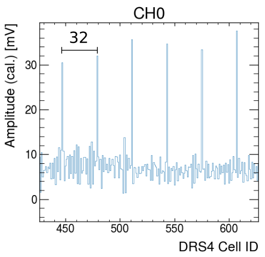
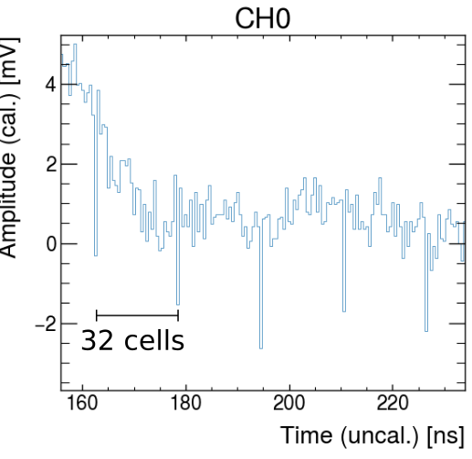
LynseyShun | Spikes/noise sensitive to clock settings? |
Hello, I now have periodic spikes in CH0 and CH1 output. How can I eliminate these spikes? I'm sorry I didn't understand your elimination method. Please explain the method in detail. Thank you very much
| Stefan Ritt wrote: |
|
elog:824
| Sean Quinn wrote: |
|
Dear DRS4 team,
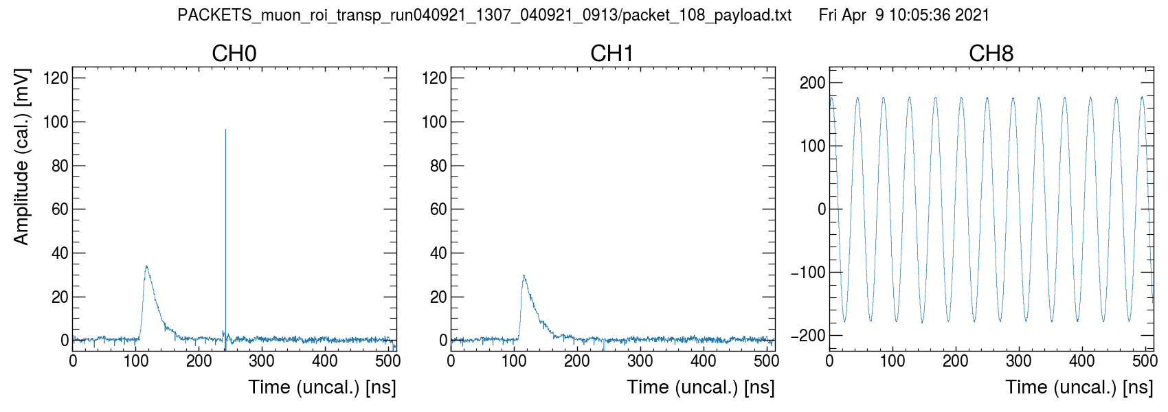
I'm trying to troubleshoot some odd spike behavior. If I run the ADC and SR CLK at 16 MHz (behavior also seen at 33 MHz) we get very noisy data (post-calibration) with periodic spikes.
In the below plot
- CH0 & CH1 are muon pulses from a scintillator + SiPM detector
- CH8 is a 25 MHz sinewave (in phase with all generated board clocks)
- Transparent mode = ON
- ROI = OFF, "full readout mode", first sample = cell 0
- DRS REFCLK = 1 MHz (2 GS/s)
- ADC & SR CLK = 16 MHz, 0 deg. offset

After I modify some clock settings, things seem to improve dramatically, and the spike behavior changes
- ADC and SR CLK = 15 MHz, 0 deg. offset
- Transparent mode = ON
- ROI = ON (just for testing purposes)
- Add 1.064 ns skew to DRS REF CLK
- NOTE: Unfortunately due to a design mishap, the ADC and FPGA clock use a phase-locked output pair on our clock synthesis chip, so we cannot fine-tune the skew for it.
Observed differences
- Spike polarity seems inverted
- Spikes limited to smaller number of cells now?
- Spike amplitude reduced
- Overall baseline variance seems better
- New large positive spike artifact on CH0 that seems inverted on CH1
- CH8 seems unaffected by large spikes?
Artifacts seem related to clock configuration, but I am sort of in the dark on what might be happening from a first-principles point of view. Any tips?
Warm regards,
Sean
|
|
|
|
521
|
Wed May 11 04:01:14 2016 |
Maksat | DRS4 Macro to save events |
Dear Stefan,
I am trying to setup DRS inside radiation enclosure and would like to write a simple script that will automatically save certain number of events.
Could you please point to me an example that can I use for Mac OS? I saw there is drs_exam.cpp in the directory but was not able to get work in Mac OS. Any help would be greatly appreciated.
Thanks
|