 Mon Mar 7 16:37:54 2022, Stefan Ritt, Scaler issue to evaluate live time Mon Mar 7 16:37:54 2022, Stefan Ritt, Scaler issue to evaluate live time 
|
I tried your measurement with the DRSOscilloscope app (see below), and I measure a constant difference of 10 Hz among the whole range of 100 Hz to 3 kHz.
So I don't know what's wrong on your side. Did you try with the oscilloscope app as well? Have you checked your pulse generator? The evaluation board time reference is a quartz with an accuracy of 10^-5, so no way one can get there a difference you see.
Stefan
| Keita Mizukoshi wrote: |
|
Thank you very much for your explanation.
I would like to show you a pulse example ('black line is the threshold).
Still, pulse generator rate and DRS4 rate are a bit different more than 10 Hz.
| Stefan Ritt wrote: |
|
The scalers are read out 10x per seconds, so they have an accuracy of 10 Hz. I tried a 50 Hz pulser, and measured 40 Hz, I tried 52 Hz and measured 50 Hz. This is about what you can expect.
The scaler rate is measured after the discriminator of the trigger, so the trigger level also affects the scaler reading. If you have a 100 mV pulse and your threshold is 200 mV, your scaler rate drops to zero. That can be seen best with the DRSOsc and sliding the trigger value. If you have a 50 Hz pulse with narrow (< us) pulses, things are fine. But if you use a 50 Hz square wave, then you get distorted signals due to the AC coupling which can also be confusing. See for example here: https://www.daqarta.com/dw_gg0o.htm
| Keita Mizukoshi wrote: |
|
Hi. I'm trying to evaluate livetime of the evaluation board with the hardware scaler. I'm facing a strange issue.
I took the rate with the function, DRS->GetScaler(int channel).
I guess that channels 0--3 mean the rate for the channel, and channel 4 means the counter of the trigger.
I took the 1,000 pulses generated by a pulse generator with 50 Hz.
The scaler values are ~ 39.83, not 50.
The timestamp difference between the initial event and the final event is 19.98 seconds.
1000/19.98 ~ 50, thus, the evaluation board took the pulses with enough livetime.
Can we believe the scaler value for the livetime evaluation?
|
|
|
|
 Fri Sep 13 15:27:41 2019, Arseny Rybnikov, Scaler / How to modify the firmware to change the scaler integration time Fri Sep 13 15:27:41 2019, Arseny Rybnikov, Scaler / How to modify the firmware to change the scaler integration time
|
Hello,
We want to use the inner DRS4 counter(scaler) within more than the 100ms integration time. We guess that we need to modify the original firmware around this point:
-- Reference clock used for frequency counter
proc_1hzclk: process(I_RESET, I_CLK33)
begin
if (I_RESET = '1') then
drs_1hz_counter(31 downto 0) <= (others => '0');
drs_1hz_clock <= '0';
scaler_reset <= (others => '1');
scaler_ff_reset <= (others => '1');
elsif rising_edge(I_CLK33) then
drs_1hz_counter <= drs_1hz_counter - 1; -- count down
scaler_reset <= (others => '0');
scaler_ff_reset <= (others => '0');
-- toggle refclk if timer expires
if (drs_1hz_counter(drs_1hz_counter'high) = '1') then
drs_1hz_clock <= not drs_1hz_clock;
drs_1hz_counter(31 downto 0) <= X"0016E35F"; -- 1499999, I_CLK33 is actually a 30 MHz clock
scaler_ff_reset <= (others => '1'); -- reset scaler_ff once every 100ms cycle
loop_scaler_reset : for i in 0 to 5 loop
if (scaler_ff(i) = '0') then -- no activity since last cycle?
scaler_reset(i) <= '1'; -- force clear scaler register
end if;
end loop;
if (scaler_ff(0) = '0') then -- no activity since last cycle?
scaler_reset(0) <= '1'; -- force clear scaler register
end if;
end if;
end if;
end process;
Could you please tell us how to modify the firmware to increse the time up to 5 seconds for instance?
Thanks in advance, Arseny |
|
Thu Nov 26 18:59:27 2015, Robert Adams, Saving histogram data
|
I would really love to be able to save histogram data, though I have not been able to do this. I could take a screenshot and extract the data from an image, but would prefer to avoid this if there is a simpler way... possibly I have overlooked something obvious? Thanks very much for any advice or tips. |
|
Tue Feb 16 11:21:43 2016, Stefan Ritt, Saving histogram data
|
There is no histogram save functoinality in ther DRSOscilloscope program - on purpose. The board and the software are meant to evaluate the board, not to replace a full DAQ system. If we want to save histograms, you maybe also want to set the range, make cuts, do fits etc. So it would take lots of resources to add all that. Therefore we recommend to use the stand-alone C program drs_exam.cpp to read the board, the you can either do whatever you want in the C program, including saving of histograms. Alternatively, you can use ROOT to analyze binary stored DRS data and do whatever histogram manipulation you want there.
Stefan
| Robert Adams wrote: |
|
I would really love to be able to save histogram data, though I have not been able to do this. I could take a screenshot and extract the data from an image, but would prefer to avoid this if there is a simpler way... possibly I have overlooked something obvious? Thanks very much for any advice or tips.
|
|
|
Tue Feb 16 11:55:54 2016, Martin Petriska, Saving histogram data
|
| Robert Adams wrote: |
|
I would really love to be able to save histogram data, though I have not been able to do this. I could take a screenshot and extract the data from an image, but would prefer to avoid this if there is a simpler way... possibly I have overlooked something obvious? Thanks very much for any advice or tips.
|
You can use qtpals, there is posibility to save histograms (energy, time diference), only set trigger on channel which you use. https://sourceforge.net/projects/qtpals/files/?source=navbar |
|
Sat Feb 2 00:13:12 2019, Hans Steiger, Saving Rate (only 15Acq/s)
|
Dear All,
when I use my Evaluation Board with some PMTs I can digitize 450 Acq/s or so. But when I want to save the waveforms the rate goes down. The Acqu. rate with saving is in the range of 14Hz up to 24 Hz.
I normally use the .txt file. I try to use the 5GS/s but also with much lower sampling rate the saving rate is not getting much better.
Is this a problem of my McBook connected to the Evaluation Board?
All the best,
Hans |
|
Sat Feb 2 10:10:22 2019, Stefan Ritt, Saving Rate (only 15Acq/s)
|
The reduction of rate is because you save in XML format, which is an ASCII format, so human readable, but takes long to write. If you switch to binary format and write on a decent fast hard disk, you should get back to 450 Acq/s.
Stefan
| Hans Steiger wrote: |
|
Dear All,
when I use my Evaluation Board with some PMTs I can digitize 450 Acq/s or so. But when I want to save the waveforms the rate goes down. The Acqu. rate with saving is in the range of 14Hz up to 24 Hz.
I normally use the .txt file. I try to use the 5GS/s but also with much lower sampling rate the saving rate is not getting much better.
Is this a problem of my McBook connected to the Evaluation Board?
All the best,
Hans
|
|
|
Wed Jul 30 11:38:58 2014, Tsutomu Nagayoshi, Sampling speed of DRS4 Board ver4
|
Hello!
I have a question concerning the sampling speed of the DRS4 evaluation board.
It is written in the manual that the sampling speed of DRS4 Evaluation Board is supported above 0.7 GHz.
However I was able to set the sampling speed to be 0.5 GHz with the function DRSBpard::SetFrequency(0.5) and realized that DRSBoard::GetTime function fills time array in every 2 ns.
I am wondering if the data taken with 0.5 GHz sampling is reliable or not.
Best regards,
Tsutomu Nagayoshi
|
|
Mon Sep 23 09:22:52 2013, Andrzej Rychter, Sampling Frequency: DRS4 eval board
|
Is it possible to set sampling frequency at 100 MHz in DRS4 eval board? Trying to set 0.1GHz in Osci program results in around 0.7 GHz. In drscl.exe i'm able to set freq at 0.1GHz but calibration is impossible.
Thank For Help!
Andrzej Rychter |
|
Mon Sep 23 09:26:56 2013, Stefan Ritt, Sampling Frequency: DRS4 eval board
|
| Andrzej Rychter wrote: |
|
Is it possible to set sampling frequency at 100 MHz in DRS4 eval board? Trying to set 0.1GHz in Osci program results in around 0.7 GHz. In drscl.exe i'm able to set freq at 0.1GHz but calibration is impossible.
Thank For Help!
Andrzej Rychter
|
700 MHz is the minimal sampling frequency. If you need 100 MHz, just buy a "normal" commercial ADC.
Best regards,
Stefan |
|
Mon Sep 23 09:51:48 2013, Andrzej Rychter, Sampling Frequency: DRS4 eval board
|
| Stefan Ritt wrote: |
|
| Andrzej Rychter wrote: |
|
Is it possible to set sampling frequency at 100 MHz in DRS4 eval board? Trying to set 0.1GHz in Osci program results in around 0.7 GHz. In drscl.exe i'm able to set freq at 0.1GHz but calibration is impossible.
Thank For Help!
Andrzej Rychter
|
700 MHz is the minimal sampling frequency. If you need 100 MHz, just buy a "normal" commercial ADC.
Best regards,
Stefan
|
OK!
Thanks for fast reply.
Andrzej |
|
Wed Mar 7 22:49:38 2018, Rodrigo Trindade de Menezes, Running drs_example.cpp
|
Hello,
We have been using the DRS4 evaluation board (S/N 2636) that works with the scope application. However we are trying to run the DRS4 evaluation board remotely by modifying the drs_exam.cpp to acquire and store data continuously.
We compiled the DRS_example.cpp without the wxWidgets but when we try to run the program, it appears to trigger on nonsense. The program appears to not be sensitive to the trigger threshold (although for very large trigger threshold it gets stuck in a waiting mode). Is there a way to ensure that the "normal" trigger mode is set? We are worried that the auto mode is running. Otherwise, not sure why the program is triggering on nonsense. By the way, it does not work with the wxWidgets compiled either so we are worried that there is an additional flag that needs to be set. The routine does not appear to conduct a calibration -- is this not necessary?
Another issue that we are having is with the data set stored on the .txt file looks incorrect. The time channel stops at 200 (but we think it should go up to 1024). In addition, the voltage channel appears to hover around small values near zero (as if triggering on noise). The output file appears this way even when we change the threshold to much higher values. It suggests that the trigger threshold is not actually being set? There are events where the output voltage appears to oscillate through huge negative and positive values too. So not sure what's going on.
Thanks!
Rodrigo |
|
Thu Mar 8 22:54:20 2018, Rodrigo Trindade de Menezes, Running drs_example.cpp
|
We found a way to solve the previous problem, but right now when we try to set the input range only -0.5 to 0.5 is working. When we set the function "SetInputRange(0.5)" for 0 to 1V the output is all zeros and with "SetInputRange(0.45)" we just get all the outputs -49.9mV. What does that means? How to fix?
| odrigo Trindade de Menezes wrote: |
|
Hello,
We have been using the DRS4 evaluation board (S/N 2636) that works with the scope application. However we are trying to run the DRS4 evaluation board remotely by modifying the drs_exam.cpp to acquire and store data continuously.
We compiled the DRS_example.cpp without the wxWidgets but when we try to run the program, it appears to trigger on nonsense. The program appears to not be sensitive to the trigger threshold (although for very large trigger threshold it gets stuck in a waiting mode). Is there a way to ensure that the "normal" trigger mode is set? We are worried that the auto mode is running. Otherwise, not sure why the program is triggering on nonsense. By the way, it does not work with the wxWidgets compiled either so we are worried that there is an additional flag that needs to be set. The routine does not appear to conduct a calibration -- is this not necessary?
Another issue that we are having is with the data set stored on the .txt file looks incorrect. The time channel stops at 200 (but we think it should go up to 1024). In addition, the voltage channel appears to hover around small values near zero (as if triggering on noise). The output file appears this way even when we change the threshold to much higher values. It suggests that the trigger threshold is not actually being set? There are events where the output voltage appears to oscillate through huge negative and positive values too. So not sure what's going on.
Thanks!
Rodrigo
|
|
|
Mon Mar 19 15:12:02 2018, Stefan Ritt, Running drs_example.cpp
|
The time channel is already calibrated in ns. So for 5 GSPS, the time scale goes from zero to 200. Concerning your other issues I will come back to you later.
Stefan
| Rodrigo Trindade de Menezes wrote: |
|
Another issue that we are having is with the data set stored on the .txt file looks incorrect. The time channel stops at 200 (but we think it should go up to 1024). In addition, the voltage channel appears to hover around small values near zero (as if triggering on noise). The output file appears this way even when we change the threshold to much higher values. It suggests that the trigger threshold is not actually being set? There are events where the output voltage appears to oscillate through huge negative and positive values too. So not sure what's going on.
|
|
|
Fri May 4 12:11:57 2018, Stefan Ritt, Running drs_example.cpp
|
And here is the second part of your answer: When you change the input range, you have to redo the voltage calibration. Best is if you do that in the DRSOsc program, then you see that it's working. Then start your custom program and use the same range.
Stefan
| Rodrigo Trindade de Menezes wrote: |
|
We found a way to solve the previous problem, but right now when we try to set the input range only -0.5 to 0.5 is working. When we set the function "SetInputRange(0.5)" for 0 to 1V the output is all zeros and with "SetInputRange(0.45)" we just get all the outputs -49.9mV. What does that means? How to fix?
| odrigo Trindade de Menezes wrote: |
|
Hello,
We have been using the DRS4 evaluation board (S/N 2636) that works with the scope application. However we are trying to run the DRS4 evaluation board remotely by modifying the drs_exam.cpp to acquire and store data continuously.
We compiled the DRS_example.cpp without the wxWidgets but when we try to run the program, it appears to trigger on nonsense. The program appears to not be sensitive to the trigger threshold (although for very large trigger threshold it gets stuck in a waiting mode). Is there a way to ensure that the "normal" trigger mode is set? We are worried that the auto mode is running. Otherwise, not sure why the program is triggering on nonsense. By the way, it does not work with the wxWidgets compiled either so we are worried that there is an additional flag that needs to be set. The routine does not appear to conduct a calibration -- is this not necessary?
Another issue that we are having is with the data set stored on the .txt file looks incorrect. The time channel stops at 200 (but we think it should go up to 1024). In addition, the voltage channel appears to hover around small values near zero (as if triggering on noise). The output file appears this way even when we change the threshold to much higher values. It suggests that the trigger threshold is not actually being set? There are events where the output voltage appears to oscillate through huge negative and positive values too. So not sure what's going on.
Thanks!
Rodrigo
|
|
|
|
Wed Jun 26 15:17:51 2019, Si Xie, Running drs_example.cpp
|
Hi Rodrigo, I'm wondering how you solved your original triggering problem. We are also having trouble with collecting data continously using the example. Thanks.
| Rodrigo Trindade de Menezes wrote: |
|
We found a way to solve the previous problem, but right now when we try to set the input range only -0.5 to 0.5 is working. When we set the function "SetInputRange(0.5)" for 0 to 1V the output is all zeros and with "SetInputRange(0.45)" we just get all the outputs -49.9mV. What does that means? How to fix?
| odrigo Trindade de Menezes wrote: |
|
Hello,
We have been using the DRS4 evaluation board (S/N 2636) that works with the scope application. However we are trying to run the DRS4 evaluation board remotely by modifying the drs_exam.cpp to acquire and store data continuously.
We compiled the DRS_example.cpp without the wxWidgets but when we try to run the program, it appears to trigger on nonsense. The program appears to not be sensitive to the trigger threshold (although for very large trigger threshold it gets stuck in a waiting mode). Is there a way to ensure that the "normal" trigger mode is set? We are worried that the auto mode is running. Otherwise, not sure why the program is triggering on nonsense. By the way, it does not work with the wxWidgets compiled either so we are worried that there is an additional flag that needs to be set. The routine does not appear to conduct a calibration -- is this not necessary?
Another issue that we are having is with the data set stored on the .txt file looks incorrect. The time channel stops at 200 (but we think it should go up to 1024). In addition, the voltage channel appears to hover around small values near zero (as if triggering on noise). The output file appears this way even when we change the threshold to much higher values. It suggests that the trigger threshold is not actually being set? There are events where the output voltage appears to oscillate through huge negative and positive values too. So not sure what's going on.
Thanks!
Rodrigo
|
|
|
|
Mon Mar 16 16:07:39 2015, Hermann-Josef Mathes, Running 2 instances of a DRS DAQ program
|
Hi,
we want to run two instances of our little DRS DAQ program but obviously the first instance started always claims all DRS boards for itself and the other one exits with an error. The 2 boards used in the example below have the serial number # 2413 and #2414 and are v5 boards.
The first one:
mathes@ikauger5:~/src/DRS4/Cpp> ./drsdaq -b 2413
DRSController: found board with serial number #2413
DRSController: found board with serial number #2414
DRSController: using board with serial number #2413
CalibratedFrequency= 1.00721
====================================
DRS type: DRS4
Board type: 9
Serial number: 2413
Firmware revision: 21260
...
And the second one:
mathes@ikauger5:~/src/DRS4/Cpp> ./drsdaq -b 2414
musb_open: usb_set_configuration() error -6
musb_open: Found USB device 0x04b4:0x1175 instance 0, but cannot initialize it: please check permissions on "/proc/bus/usb/1/7" and "/dev/bus/usb/1/7"
USB successfully scanned, but no boards found
...
How can our goal be achieved?
Thanks
Hermann-Josef |
|
Tue Mar 17 02:53:26 2015, Stefan Ritt, Running 2 instances of a DRS DAQ program
|
I never had in mind running two systems in parallel, that's why the code claims all interfaces when started. You have to dig into the usb code which is located in musbstd.c at function musb_open(). There you will find a line libusb_claim_interface() which requests exclusive access to the usb subsystem. The code is there because I copied it from some standard example for the libusb library. You have to read the documentation for libusb (http://libusb.sourceforge.net/api-1.0/) and see if you can get rid of that. Probaby you have to claim/release the interface on each access, but I never tried that.
Stefan
| Hermann-Josef Mathes wrote: |
|
Hi,
we want to run two instances of our little DRS DAQ program but obviously the first instance started always claims all DRS boards for itself and the other one exits with an error. The 2 boards used in the example below have the serial number # 2413 and #2414 and are v5 boards.
The first one:
mathes@ikauger5:~/src/DRS4/Cpp> ./drsdaq -b 2413
DRSController: found board with serial number #2413
DRSController: found board with serial number #2414
DRSController: using board with serial number #2413
CalibratedFrequency= 1.00721
====================================
DRS type: DRS4
Board type: 9
Serial number: 2413
Firmware revision: 21260
...
And the second one:
mathes@ikauger5:~/src/DRS4/Cpp> ./drsdaq -b 2414
musb_open: usb_set_configuration() error -6
musb_open: Found USB device 0x04b4:0x1175 instance 0, but cannot initialize it: please check permissions on "/proc/bus/usb/1/7" and "/dev/bus/usb/1/7"
USB successfully scanned, but no boards found
...
How can our goal be achieved?
Thanks
Hermann-Josef
|
|
|
Thu Mar 19 07:37:52 2015, Daniel Stricker-Shaver, Running 2 instances of a DRS DAQ program
|
I don't know if it helps, but we measured the time resolution between two independendly running v3 boards using a single PC (latest software) in Linux. (http://arxiv.org/abs/1405.4975)
You start the DRS DAQ program with only one USB board connected, first. Afterwards connect the second board and start another session. If you externally trigger (global) both boards with less than 1 Hz, you can garantee that both programs save the same events independently (from two individual DRS boards).
Daniel
| Stefan Ritt wrote: |
|
I never had in mind running two systems in parallel, that's why the code claims all interfaces when started. You have to dig into the usb code which is located in musbstd.c at function musb_open(). There you will find a line libusb_claim_interface() which requests exclusive access to the usb subsystem. The code is there because I copied it from some standard example for the libusb library. You have to read the documentation for libusb (http://libusb.sourceforge.net/api-1.0/) and see if you can get rid of that. Probaby you have to claim/release the interface on each access, but I never tried that.
Stefan
| Hermann-Josef Mathes wrote: |
|
Hi,
we want to run two instances of our little DRS DAQ program but obviously the first instance started always claims all DRS boards for itself and the other one exits with an error. The 2 boards used in the example below have the serial number # 2413 and #2414 and are v5 boards.
The first one:
mathes@ikauger5:~/src/DRS4/Cpp> ./drsdaq -b 2413
DRSController: found board with serial number #2413
DRSController: found board with serial number #2414
DRSController: using board with serial number #2413
CalibratedFrequency= 1.00721
====================================
DRS type: DRS4
Board type: 9
Serial number: 2413
Firmware revision: 21260
...
And the second one:
mathes@ikauger5:~/src/DRS4/Cpp> ./drsdaq -b 2414
musb_open: usb_set_configuration() error -6
musb_open: Found USB device 0x04b4:0x1175 instance 0, but cannot initialize it: please check permissions on "/proc/bus/usb/1/7" and "/dev/bus/usb/1/7"
USB successfully scanned, but no boards found
...
How can our goal be achieved?
Thanks
Hermann-Josef
|
|
|
|
Mon Feb 23 09:24:24 2009, Stefan Ritt, Rise-time measurements
|
Many applications using the DRS4 need to measure fast rising signals, like for PMTs or MCPs. This short note shows the minimal rise-times which can be measured with different input signal conditioning.
Evaluation Board
The evaluation board contains four passive transformers ADT1-1WT from Mini-Circuits to convert the single-ended input signal into a differential signal. Although these parts are rated 800 MHz bandwidth (-3dB), they have hard time to drive the DRS4 inputs. This is because at high frequencies the input impedance of DRS4 becomes pretty small (~20 Ohm at 500 MHz) due to its capacitive nature. Furthermore, each transformer drives two DRS4 inputs (channel cascading) which enhances this problem by a factor of two. We made a quick test sending a signal to the evaluation board with a rise time of 277ps and a fall time of 280ps. The result measured with the evaluation board is seen here:
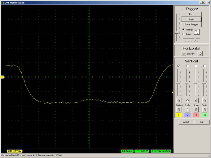
The measured rise-time (10%-90%) is only about 2ns. Disconnecting the second channel from each transformer improves this situation a bit:
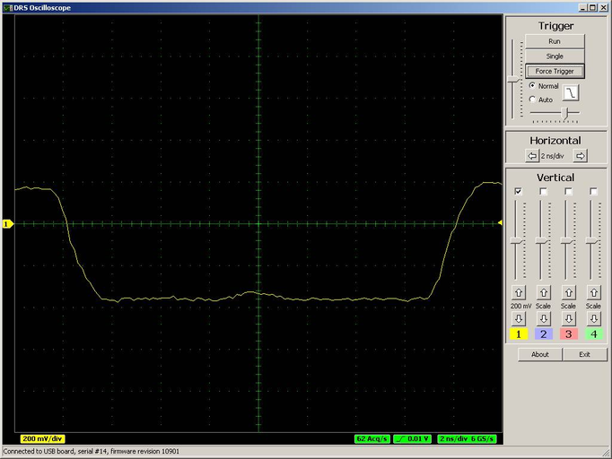
so the rise-time comes down to ~1.6ns.
Active ADA4937 driver
We tested the behavior using an active buffer ADA4937 to replace the passive transformer. Without the DRS4 connected to this buffer, we measured with the oscilloscope a rise time of 408ps and a fall time of 644ps. When we connect the DRS4 (single channel), this values increase to 702ps (rise) and 1400ps (fall), all measured with a differential oscilloscope probe (WL300 4 GHz Bandwidth, LeCroy 7300A, 3 GHz Bandwidth). In this case the rise time seen by the DRS4 is wieth ~700ps accordingly shorter:

(The signal was not properly terminated and therefore we have a small overswing).
Conclusion
To obtain an optimal rise-time measurement, the design of the input stage is rather important. A fast active driver seems to do a better job than a passive transformer (which was used on the evaluation board for power reasons). Connecting only one DRS4 channel to the input improves the rise-time measurement significantly. If channel cascading is still needed, a design should use one driver for each channel, and not driver two or more DRS4 inputs from a single buffer.
If anybody comes up with an even better input driver, I'm happy to publish the results here. |
|