 Wed Jun 10 12:46:43 2009, Stefan Ritt, Input range switch added in Version 2.1.3 Wed Jun 10 12:46:43 2009, Stefan Ritt, Input range switch added in Version 2.1.3 
|
A new software verison for the DRS4 Evaluation Board has been has been released. Version 2.1.3 adds a switch for the input range of the DRS4 board. Once can choose between -0.5V...0.5V and 0V...1V:
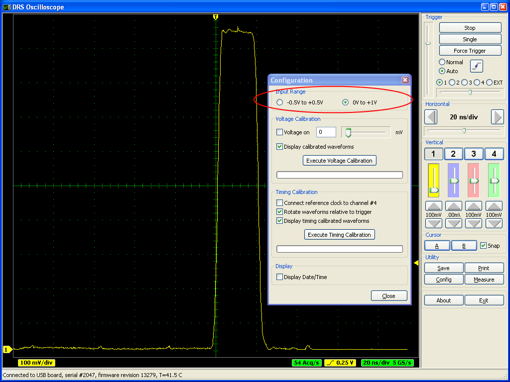
A board firmware update is not necessary for this. It was originally planned to have even a negative range -1V...0V, but this is not possible with the current board design. People who want to record negative pulses have to use an inverter to produce positive pulses. In a future version of the board it might be possible to include this functionality since this is determined by the analog front-end and not the DRS4 chip. |
 Tue Sep 5 03:28:52 2023, Matias Henriquez, Input range switch added in Version 2.1.3 Tue Sep 5 03:28:52 2023, Matias Henriquez, Input range switch added in Version 2.1.3
|
Hello,
It is not quite clear to me yet how the input range is only determined by the front end and not the DRS4 chip. According to the datasheet, the selection of ROFS determines whether the input differential range is -0.5V to 0.5V (ROFS=1.55V) or 0V to 1V (ROFS=1.05V) or -0.05V to 0.95V (ROFS=1.1V).
As far as I understand, the input differential voltage cannot go further below -0.55V since the maximum ROFS voltage is 1.6V according to the datasheet).
Also in the DRS4 evaluation board 5.1 design, the output of the differential amplifier is AC coupled to the DRS4 chip.
I'd appreciate a lot your help.
Regards,
Matias
| Stefan Ritt wrote: |
|
A new software verison for the DRS4 Evaluation Board has been has been released. Version 2.1.3 adds a switch for the input range of the DRS4 board. Once can choose between -0.5V...0.5V and 0V...1V:
A board firmware update is not necessary for this. It was originally planned to have even a negative range -1V...0V, but this is not possible with the current board design. People who want to record negative pulses have to use an inverter to produce positive pulses. In a future version of the board it might be possible to include this functionality since this is determined by the analog front-end and not the DRS4 chip.
|
|
|
Wed Sep 13 13:18:45 2023, Stefan Ritt, Input range switch added in Version 2.1.3
|
To achieve an input range of -1V to 0V, you need an external buffer which can shift this range into the DRS4 range of -0.5V to +0.5V. This external buffer has then to operate with bipolar power supplies, like -2.5V to +2.5V, which are not present on the evaluation board.
Best regards,
Stefan |
|
Thu Mar 11 21:37:32 2010, Hao Huan, Input Bandwidth of the DRS Chip
|
Hi Stefan,
I read in the DRS datasheet that the input bandwidth if 950MHz. However, it also says the output bandwidth in the transparent mode is 50MHz. Since in the transparent mode the input is routed to the output, does it mean the input bandwidth also gets reduced in the transparent mode? I don't know how the transparent mode works inside the chip of course, but this value would be important since if the hardware discriminators are connected to the output of DRS, we have to always work in the transparent mode.
Thanks!
|
|
Fri Mar 12 08:04:44 2010, Stefan Ritt, Input Bandwidth of the DRS Chip
|
| Hao Huan wrote: |
|
I read in the DRS datasheet that the input bandwidth if 950MHz. However, it also says the output bandwidth in the transparent mode is 50MHz. Since in the transparent mode the input is routed to the output, does it mean the input bandwidth also gets reduced in the transparent mode? I don't know how the transparent mode works inside the chip of course, but this value would be important since if the hardware discriminators are connected to the output of DRS, we have to always work in the transparent mode.
|
In transparent mode, the input signal also gets routed to the output, where it goes through an output buffer, which limits the bandwidth to about 50 MHz, but only for the output. The effective bandwidth to the sampling cells is not changed. Please note however that the 950 MHz are for the "chip only". We measured this by keeping the input amplitude from a function generator constant at the input pin of the chip (measured with a high speed oscilloscope). Since each signal source has a non-zero impedance, the signal tends to "shrink" at high bandwidth, and we had to adjust the level of the function generator to keep the amplitude constant at high frequencies. If you do a realistic input stage with the THS4508 for example, the achievable bandwidth will be around 800 MHz. |
|
Wed Mar 3 17:36:31 2010, Hao Huan, Initialization of the Domino Circuit
|
Hi Stefan,
I read in the datasheet that every time after power up the Domino wave in DRS4 needs to be started and stopped once to initialize the Domino circuit. However in your firmware it seems the chip immediately goes into the idle state after reset. Is that Domino circuit initialization really necessary?
Also an aside question: in your firmware the readout process has the SRCLK sent to DRS4 only about 200ns later after RSRLOAD gets asserted instead of immediately following RSRLOAD. Is there any reason for that?
Thanks a lot!
|
|
Wed Mar 3 17:49:30 2010, Stefan Ritt, Initialization of the Domino Circuit
|
| Hao Huan wrote: |
|
Hi Stefan,
I read in the datasheet that every time after power up the Domino wave in DRS4 needs to be started and stopped once to initialize the Domino circuit. However in your firmware it seems the chip immediately goes into the idle state after reset. Is that Domino circuit initialization really necessary?
Also an aside question: in your firmware the readout process has the SRCLK sent to DRS4 only about 200ns later after RSRLOAD gets asserted instead of immediately following RSRLOAD. Is there any reason for that?
Thanks a lot!
|
The start/stop requirement is obsolete and has been replaced by elog:10. I need to update this in the datasheet. The delay between the RSRLOAD and the SRCLK has the following reason: On the RSRLOAD the first sampling cell is output to the chip and to the ADC. This can sometimes be a rather high swing, which needs some time to settle, and some warm-up for the output driver. But actually I never really measured it, so it's there just as a safety margin. But I would encourage you to try to reduce this time and see it the first few bins of the readout change in offset. |
|
Tue Jul 19 02:35:04 2022, Jingyu Zhang, Increase event rate, use ROI mode, and install sw from source in Mac
|
Dear experts,
We are trying to increase the event rate of the DRS4. We looked into the ROI but couldn’t figure out how to run in ROI mode. We are wondering if there is pre-existing firmware for this? We also tried to download and build the software from source on MacOS 12.4 but we were not successful. Can you kindly help us with these?
Best regards,
Jingyu |
|
Fri Jul 29 14:09:35 2022, Stefan Ritt, Increase event rate, use ROI mode, and install sw from source in Mac
|
The firmware from the website always reads 1024 bins. You have to modify it to stop before that, like reading only 128 samples or so. For compiling under MacOSX, this should work, since I do it myself.
Regards,
Stefan
| Jingyu Zhang wrote: |
|
Dear experts,
We are trying to increase the event rate of the DRS4. We looked into the ROI but couldn’t figure out how to run in ROI mode. We are wondering if there is pre-existing firmware for this? We also tried to download and build the software from source on MacOS 12.4 but we were not successful. Can you kindly help us with these?
Best regards,
Jingyu
|
|
|
Tue Jan 31 08:10:37 2012, Stefan Ritt, IEEE Real Time 2012 Call for Abstracts
|
Hello,
I'm co-organizing the upcoming Real Time Conference, which covers also fields of waveform processing and sampling, so it might be interesting for people working with the DRS4 chip. If you have recent results, you could also consider to send an abstract to this conference. It will be nicely located in Berkeley, California. We plan excursions to San Francisco and to Napa Valley.
Best regards,
Stefan Ritt
18th Real Time Conference
June 11 – 15, 2012
Berkeley, CA
We invite you to the Hotel Shattuck Plaza in downtown Berkeley, California for
the 2012 Real-Time Conference (RT2012). It will take place Monday, June 11
through Friday, June 15, 2012, with optional pre-conference tutorials Saturday
and Sunday, June 9-10.
Like the previous editions, RT2012 will be a multidisciplinary conference
devoted to the latest developments on realtime techniques in the fields of
plasma and nuclear fusion, particle physics, nuclear physics and astrophysics,
space science, accelerators, medical physics, nuclear power instrumentation and
other radiation instrumentation.
Abstract submission is open as of 18 January (deadline 2 March). Please visit
http://www.npss-confs.org/rtc/welcome.asp?flag=44675.77&Retry=1 to submit an
abstract.
Call for Abstracts
RT 2012 is an interdisciplinary conference on realtime data acquisition and
computing applications in the physical sciences. These applications include:
* High energy physics
* Nuclear physics
* Astrophysics and astroparticle physics
* Nuclear fusion
* Medical physics
* Space instrumentation
* Nuclear power instrumentation
* Realtime security and safety
* General Radiation Instrumentation
Specific topics include (but are certainly not limited to) the list shown below.
We welcome correspondence to see how your research fits our venue.
Key Dates
* Abstract submission opened: January 18, 2012
* Abstract deadline: March 2, 2012
* Program available: April 2
Suggested Topics
* Realtime system architectures
* Intelligent signal processing
* Programmable devices
* Fast data transfer links and networks
* Trigger systems
* Data acquisition
* Processing farms
* Control, monitoring, and test systems
* Upgrades
* Emerging realtime technologies
* New standards
* Realtime safety and security
* Feedback on experiences
Contact Information
If you have a question or wish to opt in for occasional e-mail updates about
RT2012, send us a message at RT2012@lbl.gov. To view full conference
information, visit http://rt2012.lbl.gov/index.html |
|
Sat Jan 15 09:13:42 2022, student_riku, I want to know about the readout
|
Hello, everyone.
I'm a student in Japan.
Please forgive me if this is a very rudimentary question.
Am I right in thinking that inputting 1 to DMODE (Bit0) in the configuration register will connect the 1024th cell to the 1st cell?
Also, let's assume that after sampling 1024 cells on channel 0, 200 cells are sampled in the second week.
Does the readout of 1024 cells start from cell 0?
Or does it start from the 200th cell? |
|
Sat Jan 15 10:50:47 2022, Stefan Ritt, I want to know about the readout
|
| student_riku wrote: |
|
Am I right in thinking that inputting 1 to DMODE (Bit0) in the configuration register will connect the 1024th cell to the 1st cell?
|
Yes, as desceribed in the manual .
| student_riku wrote: |
|
Also, let's assume that after sampling 1024 cells on channel 0, 200 cells are sampled in the second week.
Does the readout of 1024 cells start from cell 0?
Or does it start from the 200th cell?
|
I don't understand what you mean by "second week".
Normally, you run the chip continously (DMODE=1) until you receive a trigger. Then, you typically read out the chip from the stop position by using a RSRLOAD pulse (as described unter "REGION-OF-INTEREST READOUT MODE".
Stefan |
|
Wed Jan 26 06:44:11 2022, student_riku, I want to know about the readout
|
Dear Stefan
Thanks a lot.
I solved it.
| Stefan Ritt wrote: |
| student_riku wrote: |
|
Am I right in thinking that inputting 1 to DMODE (Bit0) in the configuration register will connect the 1024th cell to the 1st cell?
|
Yes, as desceribed in the manual .
| student_riku wrote: |
|
Also, let's assume that after sampling 1024 cells on channel 0, 200 cells are sampled in the second week.
Does the readout of 1024 cells start from cell 0?
Or does it start from the 200th cell?
|
I don't understand what you mean by "second week".
Normally, you run the chip continously (DMODE=1) until you receive a trigger. Then, you typically read out the chip from the stop position by using a RSRLOAD pulse (as described unter "REGION-OF-INTEREST READOUT MODE".
Stefan
|
|
|
Mon Oct 31 09:15:02 2011, Zhongwei Du, How to link PMT
|
I want to measure the signal from PMT . But it is a current signal, should i just put a series resistance, or use a amplifier to convert it to voltage signal before drs4?
Can you give me some advice ? |
|
Tue Nov 1 11:07:02 2011, Stefan Ritt, How to link PMT
|
| Zhongwei Du wrote: |
|
I want to measure the signal from PMT . But it is a current signal, should i just put a series resistance, or use a amplifier to convert it to voltage signal before drs4?
Can you give me some advice ?
|
The evaluation board has a 50 Ohm termination resistor, which already converts your current into a voltage signal. If the resulting signal is too low (<20 mV) you can put in an amplifier or raise the HV of your PMT (inside the valid range given by its datasheet of course).
- Stefan |
|
Wed Mar 2 17:25:10 2022, Matias Senger, How to convert samples to volt?
|
I am using the `drscl` app. My prior experience is practically zero, sorry if this is a very naive question. When I read using `read 0 1` (channel 0, with calibration) I get this:
```
Calibration not valid for board #2946
10 3 7 4 10 8 14 5 5 9 3 4 9 8 9 4
3 3 12 5 5 13 3 8 1 5 0 4 8 6 6 3
...etc...
```
Why does it says that the calibration is not valid? How am I supposed to go from integers to volts?
If I run the `info` command I get this:
```
==============================
Mezz. Board index: 0
DRS type: DRS4
Board type: 9
Serial number: 2946
Firmware revision: 30000
Temperature: 43.4 C
Input range: -0.5V...0.5V
Calibrated range: -0.5V...0.5V
Calibrated frequency: 0.000 GHz
Status reg.: 0000009A
Control reg.: 00000000
DMODE circular
Trigger bus: 00000000
Frequency: 1.007 GHz
``` |
|
Thu Mar 3 13:47:26 2022, Stefan Ritt, How to convert samples to volt?
|
The 'drscl' tool is more for experts, normal users are advised to use the DRSOsc oscilloscope.
The board has to be calibrated for a given sampling speed before calibrated data can be read out. Do that with the "calib" command, specifying 5 for the sampling rate, 0 for the range (which is the middle between -0.5 and +0.5) and 1 for 1024 mode. If you then do "start", "stop", "read 0 1" you get calibrated data in mV.
Stefan
| Matias Senger wrote: |
|
I am using the `drscl` app. My prior experience is practically zero, sorry if this is a very naive question. When I read using `read 0 1` (channel 0, with calibration) I get this:
```
Calibration not valid for board #2946
10 3 7 4 10 8 14 5 5 9 3 4 9 8 9 4
3 3 12 5 5 13 3 8 1 5 0 4 8 6 6 3
...etc...
```
Why does it says that the calibration is not valid? How am I supposed to go from integers to volts?
If I run the `info` command I get this:
```
==============================
Mezz. Board index: 0
DRS type: DRS4
Board type: 9
Serial number: 2946
Firmware revision: 30000
Temperature: 43.4 C
Input range: -0.5V...0.5V
Calibrated range: -0.5V...0.5V
Calibrated frequency: 0.000 GHz
Status reg.: 0000009A
Control reg.: 00000000
DMODE circular
Trigger bus: 00000000
Frequency: 1.007 GHz
```
|
|
|
Thu Mar 14 03:43:49 2019, Deepak Samuel, How to buy DRS evaluation kit
|
Dear Stefan,
I have emailed drs4@psi.ch a couple of times regarding the pricing of the evaluation kits for academic use in India and have not received any reply and hence writing in this forum. Could you please help me in this?
Thanks and regards,
Deepak Samuel. |
|
Wed May 26 19:18:09 2010, Hao Huan, High Frequency Input for DRS
|
Hi Stefan,
I read in the DRS datasheet that the bandwidth for the transparent mode OUT+ is only 200MHz which I think cannot be improved by any active input buffer; so if you want to operate the chip for really high frequency input, would it be better to feed on-board discriminators not from the output of DRS but from the input end?
Thanks!
|
|
Tue Jun 1 13:36:18 2010, Stefan Ritt, High Frequency Input for DRS
|
| Hao Huan wrote: |
|
Hi Stefan,
I read in the DRS datasheet that the bandwidth for the transparent mode OUT+ is only 200MHz which I think cannot be improved by any active input buffer; so if you want to operate the chip for really high frequency input, would it be better to feed on-board discriminators not from the output of DRS but from the input end?
Thanks!
|
First, the 200 MHz is not correct. Table 1 clearly states ANALOG OUTPUTS - Bandwidth (-3dB): 50 MHz. This is also shown in plot 11 (revision 0.9). But that does not necessarily mean that you have to drive your discriminators from the input of the DRS4 chip. If you use this for triggering, a 1-2 ns timing jitter does not matter, since stopping the domino wave anyhow has a 3-4 cell jitter. If you send a very fast signal though a 50 MHz low pass filter, the timing anyhow doe not change, only the slope of your signal gets lower, so you are more sensitive to noise, which in turn causes the 1-2 ns timing jitter. But I personally would not worry about that too much. Putting any signal splitting components in the input path would reduce the input bandwidth, which would be much more of an issue. |
|