| ID |
Date |
Author |
Subject |
|
862
|
Sat Feb 12 13:06:56 2022 |
Matias Senger | Cannot trigger on pulses, have to trigger on undershoot | I am using the DRS4 board trying to measure pulses produced by an LGAD. I have no prior experience with this board, have just installed the `drsosc` application and am exploring. I am experiencing some strange trigger behavior. Consider the following screenshot:

Here nothing is strange, the board is triggering on the undershoot and it is working fine, I can trigger on rising/falling edge, different levels, etc.
Now, the strange thing is that if I pull the trigger up to trigger on the pulse itself it stops triggering:

I have tried many different setups for the trigger (rising, falling edge, different levels, etc) and nothing works. In the undershoot, everything works.
I have tried with the internal test signal and it works fine:

What could be the problem?
I have run the voltage and time calibrations as suggested in the manual. |
|
867
|
Wed Mar 2 17:25:10 2022 |
Matias Senger | How to convert samples to volt? | I am using the `drscl` app. My prior experience is practically zero, sorry if this is a very naive question. When I read using `read 0 1` (channel 0, with calibration) I get this:
```
Calibration not valid for board #2946
10 3 7 4 10 8 14 5 5 9 3 4 9 8 9 4
3 3 12 5 5 13 3 8 1 5 0 4 8 6 6 3
...etc...
```
Why does it says that the calibration is not valid? How am I supposed to go from integers to volts?
If I run the `info` command I get this:
```
==============================
Mezz. Board index: 0
DRS type: DRS4
Board type: 9
Serial number: 2946
Firmware revision: 30000
Temperature: 43.4 C
Input range: -0.5V...0.5V
Calibrated range: -0.5V...0.5V
Calibrated frequency: 0.000 GHz
Status reg.: 0000009A
Control reg.: 00000000
DMODE circular
Trigger bus: 00000000
Frequency: 1.007 GHz
``` |
|
871
|
Sun Mar 6 17:54:47 2022 |
Matias Senger | Why does not trigger at higher sampling frequencies? | I have connected 3 signals to the DRS4 Evaluation Board V5 which look like this in the drsosc app:

Note that here I am sampling at 5 GS/s. Using this app everything works perfect.
Now I want to repeat this using the C++ API (which I am actually wrapping to use within Python, see here if interested https://github.com/SengerM/pydrs ) but can only make this to work at lower sampling frequencies up to 3.9 GS/s. This is how I am configuring the board followint the `drs_exam.cpp` file:
```python
board.set_sampling_frequency(Hz=SAMPLING_FREQ)
board.set_transparent_mode('on')
board.set_input_range(center=0)
board.enable_trigger(True,False) # Don't know what this line does, it was in the example `drs_exam.cpp`.
board.set_trigger_source('ch4')
board.set_trigger_level(volts=-.1)
board.set_trigger_polarity(edge='falling')
board.set_trigger_delay(seconds=TRIGGER_DELAY)
```
The full code is here https://github.com/SengerM/pydrs/blob/master/tests/test_drs.py but anyway, my previous snippet can be considered as pseudo-code and if more details needed I can provide.
This is what I get as I increase the sampling frequency:


Up to 3.95 GS/s it works perfectly. At >= 4 GS/s it just never triggers. A few times I was able to make this work at 4 and 5 GS/s playing with the trigger delay, but this seemed to be some kind of random luck because I was not able to replicate it even with the same values.
Any help is appreciated.
Best,
Matías. |
|
875
|
Tue Mar 8 00:25:56 2022 |
Matias Senger | Why does not trigger at higher sampling frequencies? | I have seen in the app that the trigger source buttons do something different than the "or" and "transparent trigger" buttons:

If I enable the setup from the right, i.e. OR in CH4 and "Enable Transparent Trigger" the app stops triggering. This is the configuration that seems to be applied in the `drs_exam.cpp` code if I am not mistaken. For some reason in that code it still triggers (I have modified the code to trigger on CH4 instead of CH1 and the trigger level, polarity, etc.).
What does the button in the left actually do? The circular checkbox with the "4" I mean. This is the trigger configuration I want to get in the C++ code.
I also don't know what the function `DRSBoard::EnableTrigger` does, what is the meaning of `flag1` and `flag2`? In my code there is a call to this function which I copied from the example.
| Stefan Ritt wrote: |
|
Unfortunately I have not idea what the problem could be. In principle the trigger should be independent of the sampling speed, since the trigger is only made with a discriminator and a flip-flop. The hardware must be ok since you see the trigger with the oscillocope app. All you can do is to go through the sorce code of the oscilloscope app, especially drsosc/Osic.cpp::ScanBoards(), SetTriggerLevel(), SetTriggerPolariy() etc. to make sure you do the same calls as the oscilloscope app.
Stefan
|
|
|
876
|
Tue Mar 8 12:20:00 2022 |
Matias Senger | Why does not trigger at higher sampling frequencies? | Sorry for the spam. Just want to let you know that I was able to solve the problem, it was all due to a `float` being casted as `int` in the Python binding. Now it works like a charm.
| Matias Senger wrote: |
|
I have seen in the app that the trigger source buttons do something different than the "or" and "transparent trigger" buttons:
If I enable the setup from the right, i.e. OR in CH4 and "Enable Transparent Trigger" the app stops triggering. This is the configuration that seems to be applied in the `drs_exam.cpp` code if I am not mistaken. For some reason in that code it still triggers (I have modified the code to trigger on CH4 instead of CH1 and the trigger level, polarity, etc.).
What does the button in the left actually do? The circular checkbox with the "4" I mean. This is the trigger configuration I want to get in the C++ code.
I also don't know what the function `DRSBoard::EnableTrigger` does, what is the meaning of `flag1` and `flag2`? In my code there is a call to this function which I copied from the example.
| Stefan Ritt wrote: |
|
Unfortunately I have not idea what the problem could be. In principle the trigger should be independent of the sampling speed, since the trigger is only made with a discriminator and a flip-flop. The hardware must be ok since you see the trigger with the oscillocope app. All you can do is to go through the sorce code of the oscilloscope app, especially drsosc/Osic.cpp::ScanBoards(), SetTriggerLevel(), SetTriggerPolariy() etc. to make sure you do the same calls as the oscilloscope app.
Stefan
|
|
|
|
877
|
Fri Mar 11 17:26:15 2022 |
Matias Senger | Time calibration and the C++ API | I am using the V5 board at a fixed sampling frequency. With the `drsosc` app I have executed the time calibration at 5 GS/s (actually 5.12 GS/s). This is how my setup looks like in the app:

Now I want to replicate this using the C++ API (not the positive width measurement shown, the signal sampling only). I am seting the sampling frequency to 5 GS/s, as I do in the `drsosc` app. Then I get the time information using the `DRSBoard::GetTime(unsigned int chipIndex, int channelIndex, int tc, float *time)` function (which I don't find defined either in `DRS.h` or `DRS.cpp` but somehow it works). How can I know if these times that I get here are being corrected with the time calibration? If so, should I expect the time resolution to be < 3 ps? Are these 3 ps accumulative, such that in the end I end up having a contribution from the evaluation board of 3 ps × 5 Gs/s × 100 ns where 100 ns is the time difference between my two pulses? (This does not seem to be the case because if so I would expect the jitter to be ~ 1 ns, and we see that the "Pos Width" measurement is ~ 0.1 ns std.)
Why am I asking? I want to measure the jitter between the two falling edges. This cannot be done easily with the `drsosc` app I think, so I am acquiring the data and doing this offline. I have done this measurement in the past using a LeCroy WaveRunner oscilloscope with 20 GS/s and 4 GHz bandwidth (offline, same code) and I have seen it vary from ~5 ps → 30 ps when I vary a voltage that I can control. Now if I calculate this time fluctuation using the data acquired with the V5 evaluation board I get a value ~100 ps and independent of this voltage, which leads me to conclude that the limiting factor is being the evaluation board itself. So now I am wondering if I have reached its limit, or if there is some setting that can still improve this result.
Thanks! |
|
879
|
Sat Mar 12 16:52:36 2022 |
Matias Senger | Time calibration and the C++ API | Dear Stefan,
For the time of each bin I am using the values returend by `GetTime` without any assumption by my side. I did not notice before that the sampling time is not uniform, but I see that this is already happening. This is an example plot from one of the signals I processed:

The bin at 65.5 ns and the next one are closer than their neighbors. So this seems to indicate that the time calibration is being taken into account when I acquire the time bins using `GetTime`, is this correct?
To obtain the final time resolution I am using the constant fraction discriminator method and the signals are linearly interpolated to obtain the time at each percentage value, as seen in the plot. I have already measured time resolutions in the 5-100 ps range with exactly the same setup but using the LeCroy oscilloscope, which I am using just for data acquisition, and my software for offline analysis as shown in the plot above. Now what I am trying to do is to replace the LeCroy by the DRS4 Evaluation Board basically, so I can use the oscilloscope in a different setup.
Best,
Matias.
| Stefan Ritt wrote: |
|
DRSBoard::GetTime is declared in DRS.h line 720.
If you want to measure timing down to ps, you need some basic knowledge, especially about signal-to-noise and risetime. This cannot be taught in a few sentenses, needs a full lecture. As a starting point please read that papat:
https://arxiv.org/abs/1405.4975
then you will understand why you measure different resolutions with different peak heights (and different rise times).
Concerning the DRS4 measurement, please be aware that the sampling poings are not equidistant, like not every 200ps for GSPS. They vary bin by bin significantly, from 50ps to 300ps. So you alway have to analyse the X/Y points as an array, not just the Y values assuming deltaX of 200ps. Probably you forgot that. Then, you have to interpolate between bins to find the crossing over your threshold. Linear interpolation is already good, spline interpolation even better. Deep inside Measurement.cpp of the drsosc program you find in the source code:
t1 = (thr*(x1[i]-x1[i-1])+x1[i-1]*y1[i]-x1[i]*y1[i-1])/(y1[i]-y1[i-1]);
which is the linear interpolation (thr is the threshold). You have to use (and understand!) similar code.
Best,
Stefan
| Matias Senger wrote: |
|
I am using the V5 board at a fixed sampling frequency. With the `drsosc` app I have executed the time calibration at 5 GS/s (actually 5.12 GS/s). This is how my setup looks like in the app:
Now I want to replicate this using the C++ API (not the positive width measurement shown, the signal sampling only). I am seting the sampling frequency to 5 GS/s, as I do in the `drsosc` app. Then I get the time information using the `DRSBoard::GetTime(unsigned int chipIndex, int channelIndex, int tc, float *time)` function (which I don't find defined either in `DRS.h` or `DRS.cpp` but somehow it works). How can I know if these times that I get here are being corrected with the time calibration? If so, should I expect the time resolution to be < 3 ps? Are these 3 ps accumulative, such that in the end I end up having a contribution from the evaluation board of 3 ps × 5 Gs/s × 100 ns where 100 ns is the time difference between my two pulses? (This does not seem to be the case because if so I would expect the jitter to be ~ 1 ns, and we see that the "Pos Width" measurement is ~ 0.1 ns std.)
Why am I asking? I want to measure the jitter between the two falling edges. This cannot be done easily with the `drsosc` app I think, so I am acquiring the data and doing this offline. I have done this measurement in the past using a LeCroy WaveRunner oscilloscope with 20 GS/s and 4 GHz bandwidth (offline, same code) and I have seen it vary from ~5 ps → 30 ps when I vary a voltage that I can control. Now if I calculate this time fluctuation using the data acquired with the V5 evaluation board I get a value ~100 ps and independent of this voltage, which leads me to conclude that the limiting factor is being the evaluation board itself. So now I am wondering if I have reached its limit, or if there is some setting that can still improve this result.
Thanks!
|
|
|
|
881
|
Tue Mar 15 13:07:50 2022 |
Matias Senger | Time calibration and the C++ API | Thanks for your help. If I look into the app the behavior for the 4 channels is exactly as you show:


Now, when I sample with my code something strange happens, two of the channels are fine and the other two are wrong:

This is a surprise to me because I acquire the 4 channels in the same way within a `for` loop. To get the time data I use `DRSBoard::GetTime` with the `tcalibrated` argument set to `true`. Is there any aditional step to use the calibration?
Best,
Matias.
| Stefan Ritt wrote: |
|
Looks like you have the some time calibration, not sure if it's the correct one. Sample the sine wave from the calibration clock, once with and once without the timing calibration, then you will see if all points lie on a smooth line. Left: without timing calibration, right: with proper timing calibration:
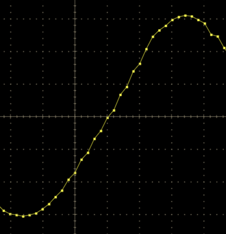 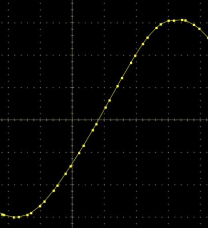
If your points do not lie on a smooth line, you might habe a problem such as the wrong channel for calibration, an offset of 1 in the index of the time array or some other software bug. Measure the same signal with the DRSOsc application and then your code. If the results differ, you have a software problem on your side.
Stefan
|
|
|
901
|
Tue Sep 5 03:28:52 2023 |
Matias Henriquez | Input range switch added in Version 2.1.3 | Hello,
It is not quite clear to me yet how the input range is only determined by the front end and not the DRS4 chip. According to the datasheet, the selection of ROFS determines whether the input differential range is -0.5V to 0.5V (ROFS=1.55V) or 0V to 1V (ROFS=1.05V) or -0.05V to 0.95V (ROFS=1.1V).
As far as I understand, the input differential voltage cannot go further below -0.55V since the maximum ROFS voltage is 1.6V according to the datasheet).
Also in the DRS4 evaluation board 5.1 design, the output of the differential amplifier is AC coupled to the DRS4 chip.
I'd appreciate a lot your help.
Regards,
Matias
| Stefan Ritt wrote: |
|
A new software verison for the DRS4 Evaluation Board has been has been released. Version 2.1.3 adds a switch for the input range of the DRS4 board. Once can choose between -0.5V...0.5V and 0V...1V:
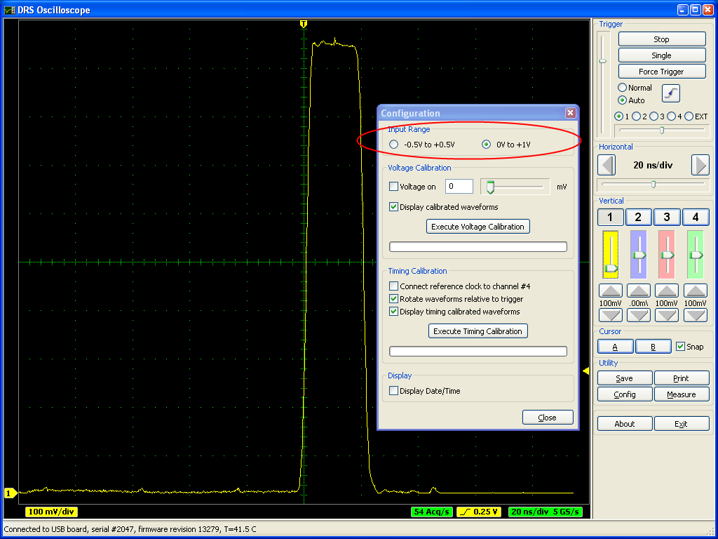
A board firmware update is not necessary for this. It was originally planned to have even a negative range -1V...0V, but this is not possible with the current board design. People who want to record negative pulses have to use an inverter to produce positive pulses. In a future version of the board it might be possible to include this functionality since this is determined by the analog front-end and not the DRS4 chip.
|
|
|
910
|
Fri Dec 20 20:35:31 2024 |
Matias Henriquez | Problem with C++ script to use DRS4 evaluation board. Not taking data. | Hello,
I need to write a script in C++ to take data using the DRS4 evaluation board v4. For that, I used the drs_exam.cpp example as a reference. This is my code (see attachement 2), which is very similar to the provided example, however the difference is that I need to trigger on CH1 OR CH2. In the next version I will need to trigger with an OR in all channels.
The problem is, my code gets stuck in waiting for trigger or only 1 event occurs (event 0). I read that event and it doesn't even go above 30mV, which was the threshold I set. There are some questions I have:
- Why Transparent mode is activated for Hardware Trigger?
- Why EnableTCal is activated? is the drs4_exam example based acquires the 100MHz reference just for the sake of the example? or is just a time calibration routine?
- Can someone explain the function EnableTrigger(flag1,flag2) in boardType 8? it si not clear to me how the trigger is enabled.
- To check that my input signals are correct, I run the drsosc application and I can see the signals with no problem (see attachement 1). However I noticed that I had to configure the trigger delay in the drsosc application, and I don't do that in my c++ code. I will try that later.
- How do I perform voltage calibration and time calibration using the c++ functions?
Thank you so much for your help.
|
| Attachment 1: 1.png
|

|
| Attachment 2: drs_test.cpp
|
/********************************************************************\

  Name:         drs_exam.cpp
  Created by:   Stefan Ritt

  Contents:     Simple example application to read out a DRS4
               evaluation board

  $Id: drs_exam.cpp 21308 2014-04-11 14:50:16Z ritt $

\********************************************************************/

#include <math.h>

#ifdef _MSC_VER

#include <windows.h>

#elif defined(OS_LINUX)

#define O_BINARY 0

#include <unistd.h>
#include <ctype.h>
#include <sys/ioctl.h>
#include <errno.h>

#define DIR_SEPARATOR '/'

#endif

#include <stdio.h>
#include <string.h>
#include <stdlib.h>

#include "strlcpy.h"
#include "DRS.h"

/*------------------------------------------------------------------*/

int main()
{
   int i, j, nBoards;
   DRS *drs;
   DRSBoard *b;
   float time_array[8][1024];
   float wave_array[8][1024];
   FILE  *f;

   double domino_freq = 2; //Domino Ring Frequency = 2GHz
   double trigger_level_ch1 = 0.03; // Trigger level for channel 1
   double trigger_level_ch2 = 0.03; // Trigger level for channel 2
   //double trigger_level_ch3 = 0.01; // Trigger level for channel 3
   //double trigger_level_ch4 = 0.01; // Trigger level for channel 4

   int trigger_source_reg = (1<<0) + (1<<1);
   //int trigger_source_reg = (1<<0) + (1<<1) + (1<<2) + (1<<3);

   /* do initial scan */
   drs = new DRS();

   /* show any found board(s) */
   for (i=0 ; i<drs->GetNumberOfBoards() ; i++) {
      b = drs->GetBoard(i);
      printf("Found DRS4 evaluation board, serial #%d, firmware revision %d\n",
         b->GetBoardSerialNumber(), b->GetFirmwareVersion());
   }

   /* exit if no board found */
   nBoards = drs->GetNumberOfBoards();
   if (nBoards == 0) {
      printf("No DRS4 evaluation board found\n");
      return 0;
   }

   /* continue working with first board only */
   b = drs->GetBoard(0);

   /* initialize board */
   b->Init();

   /* set sampling frequency */
   b->SetFrequency(domino_freq, true);

   /* enable transparent mode needed for analog trigger */
   b->SetTranspMode(0);

   /* set input range to -0.5V ... +0.5V */
   //b->SetInputRange(0.5);

   /* use following line to set range to 0..1V */
   b->SetInputRange(0.45);

   /* use following line to turn on the internal 100 MHz clock connected to all channels  */
   //b->EnableTcal(1);

   /* use following lines to enable hardware trigger on */
   if (b->GetBoardType() >= 8) {        // Evaluaiton Board V4&5
      b->EnableTrigger(1, 0);           // enable hardware trigger
      //b->SetTriggerSource(1<<0);
   } else if (b->GetBoardType() == 7) { // Evaluation Board V3
      b->EnableTrigger(0, 1);           // lemo off, analog trigger on
      //b->SetTriggerSource(0);
   }
   //b->SetTriggerLevel(0.05);            // 0.05 V
   b->SetTriggerPolarity(false);        // positive edge

   /* use following lines to set individual trigger elvels */
   b->SetIndividualTriggerLevel(1, trigger_level_ch1);
   b->SetIndividualTriggerLevel(2, trigger_level_ch2);
   //b->SetIndividualTriggerLevel(3, trigger_level_ch3);
   //b->SetIndividualTriggerLevel(4, trigger_level_ch4);
   //Set Trigger Configuration
   // OR Bit0 = CH1, Bit1 = CH2, Bit2 = CH3, Bit3 = CH4, Bit4 = EXT
   // AND Bit8 = CH1, Bit9 = CH2, Bit10 = CH3, Bit11 = CH4, Bit12 = EXT
   // TRANSP Bit15
   b->SetTriggerSource(trigger_source_reg);

   b->SetTriggerDelayNs(0);             // zero ns trigger delay

   /* use following lines to enable the external trigger */
   //if (b->GetBoardType() == 8) {     // Evaluaiton Board V4
   //   b->EnableTrigger(1, 0);           // enable hardware trigger
   //   b->SetTriggerSource(1<<4);        // set external trigger as source
   //} else {                          // Evaluation Board V3
   //   b->EnableTrigger(1, 0);           // lemo on, analog trigger off
   // }

   /* open file to save waveforms */
   f = fopen("data.txt", "w");
   if (f == NULL) {
      perror("ERROR: Cannot open file \"data.txt\"");
      return 1;
   }

   /* repeat ten times */
   for (j=0 ; j<10 ; j++) {

      /* start board (activate domino wave) */
      b->StartDomino();

      /* wait for trigger */
      printf("Waiting for trigger...");

      fflush(stdout);
      while (b->IsBusy());

      /* read all waveforms */
      b->TransferWaves(0, 8);

      /* read time (X) array of first channel in ns */
      b->GetTime(0, 0, b->GetTriggerCell(0), time_array[0]);

      /* decode waveform (Y) array of first channel in mV */
      b->GetWave(0, 0, wave_array[0]);

      /* read time (X) array of second channel in ns
       Note: On the evaluation board input #1 is connected to channel 0 and 1 of
       the DRS chip, input #2 is connected to channel 2 and 3 and so on. So to
       get the input #2 we have to read DRS channel #2, not #1. */
      b->GetTime(0, 2, b->GetTriggerCell(0), time_array[1]);

      /* decode waveform (Y) array of second channel in mV */
      b->GetWave(0, 2, wave_array[1]);

      /* Save waveform: X=time_array[i], Yn=wave_array[n][i] */
      fprintf(f, "Event #%d ----------------------\n  t1[ns]  u1[mV]  t2[ns] u2[mV]\n", j);
      for (i=0 ; i<1024 ; i++)
         fprintf(f, "%7.3f %7.1f %7.3f %7.1f\n", time_array[0][i], wave_array[0][i], time_array[1][i], wave_array[1][i]);

      /* print some progress indication */
      printf("\rEvent #%d read successfully\n", j);
   }

   fclose(f);

   /* delete DRS object -> close USB connection */
   delete drs;
}
|
|
911
|
Mon Dec 23 19:31:31 2024 |
Matias Henriquez | Trigger OUT pulse width variable from 100 us up to 100 ms | Given this new scenario, what is the maximum rate of events that can be processed then (a rough estimation would be great, 1/2ms?)? is it mainly limited by the USB data transmission and the PC? How does the logic of the trigger and DRS4 data sampling works inside the FPGA in general terms? e.g: trigger activated -> dwrite ON -> ADC acquisition -> busy until data has been shipped off to the PC -> free to process new events.
Is there a way to obtain some sort of timestamp for the trigger on each event? or is it better to use C++ time functions in the PC since the DRS4 is usually used in experiments with low rate of events so the long time it takes to the USB and PC is not a problem? (eg. particle physics).
Thanks for your help,
Matias H.
| Stefan Ritt wrote: |
|
The "Trigger OUT" has changed recently. It goes high on a new trigger, but then STAYS high until the board has been read out by the PC and re-started. This allows better synchronization with some external trigger, which can be re-armed with the falling edge of the trigger out signal. The signal can be quite long, since readout of an event via USB typically takes 2 ms, but can be more if the PC is busy. If you need back your 150 ns pulse, send the trigger out to an external pulse shaper with fixed shaping width.
Stefan
| Gerard Arino-Estrada wrote: |
|
Hello Stefan,
I am using the DRS4 board connected to a Raspberry PI and through the drsosc application. I am interested on using the "Trigger OUT" signal to do some extra data processing with NIM modules. According to the manual, for each hardware trigger a TTL pulse of 150 ns width should be send through the "trigger OUT". In my case I do see pulses with widths ranging from 100 microseconds up to hundreds of miliseconds. I am connecting the signal directly to an oscilloscope with 50 Ohm termination. I have tried two DRS4 boards in identical conditions and both show the same behavior. Having such wide and variable pulses makes it complicated for me to do the extra post-processing. Have you any idea of what might be going wrong? Thank you very much.
Best regards,
Gerard
|
|
|
|
912
|
Fri Dec 27 22:04:48 2024 |
Matias Henriquez | Problem with C++ script to use DRS4 evaluation board. Not taking data. | Hello, some updates:
4. I was able to capture correct waveforms using c++ code. I needed to use the function SetTriggerDelayNs() to properly capture my waveforms.
5. I noticed that the drsosc program source code uses the functions: CalibrateVolt() and CalibrateTiming() for performing calibration. For these to work, is it necessary to use EnableAcal() and EnableTcal() functions right?
I'd appreciate if you can still give some insights about 1,2 and 3. Thank you!
| Matias Henriquez wrote: |
|
Hello,
I need to write a script in C++ to take data using the DRS4 evaluation board v4. For that, I used the drs_exam.cpp example as a reference. This is my code (see attachement 2), which is very similar to the provided example, however the difference is that I need to trigger on CH1 OR CH2. In the next version I will need to trigger with an OR in all channels.
The problem is, my code gets stuck in waiting for trigger or only 1 event occurs (event 0). I read that event and it doesn't even go above 30mV, which was the threshold I set. There are some questions I have:
- Why Transparent mode is activated for Hardware Trigger?
- Why EnableTCal is activated? is the drs4_exam example based acquires the 100MHz reference just for the sake of the example? or is just a time calibration routine?
- Can someone explain the function EnableTrigger(flag1,flag2) in boardType 8? it si not clear to me how the trigger is enabled.
- To check that my input signals are correct, I run the drsosc application and I can see the signals with no problem (see attachement 1). However I noticed that I had to configure the trigger delay in the drsosc application, and I don't do that in my c++ code. I will try that later.
- How do I perform voltage calibration and time calibration using the c++ functions?
Thank you so much for your help.
|
|
|
119
|
Wed Jun 1 09:57:43 2011 |
Martin Petriska | Removing spikes | I have DSR4 eval board. Found that there are spikes in channels. Procedure Osc::RemoveSpikes to remove them looks litlle dificult. There is simple way, if you doesnt need to measure all 4 channels.Spikes are in all channels, and it looks like they are same in time and value between channels. To remove them, if you are not using one channel, substract that unused channel with spikes from used channel and your data will be without spikes. If you need all 4 inputs, then may be channel 9 could be substracted. |
|
158
|
Tue Mar 20 16:23:33 2012 |
Martin Petriska | triger for measuring time between pulses in channels | I have two BaF2 detectors with PMT connected to Ch1 and Ch2. At this time Im using external triger module to start DRS4. My evalution board is version 3 so I have no possibility to trigger on two or more pulses occurence on different channels. But I have this idea, trigger with analog trigger on channel 1 (start detector) will start measurement on all channels. After that using FPGA inside EVM to look if some value in Ch2 is bigger as treshold value for example 0,5V and if yes then send data by USB to PC, if signal in Ch2 is lower then restart measurement and wait on triger in Ch1. This way I want to eliminate false data transfer throw USB. Is this possible to implement it into DRS4 evaluation board firmware ?
Thanks. |
|
160
|
Wed Mar 21 09:33:00 2012 |
Martin Petriska | triger for measuring time between pulses in channels |
| Stefan Ritt wrote: |
|
| Martin Petriska wrote: |
|
I have two BaF2 detectors with PMT connected to Ch1 and Ch2. At this time Im using external triger module to start DRS4. My evalution board is version 3 so I have no possibility to trigger on two or more pulses occurence on different channels. But I have this idea, trigger with analog trigger on channel 1 (start detector) will start measurement on all channels. After that using FPGA inside EVM to look if some value in Ch2 is bigger as treshold value for example 0,5V and if yes then send data by USB to PC, if signal in Ch2 is lower then restart measurement and wait on triger in Ch1. This way I want to eliminate false data transfer throw USB. Is this possible to implement it into DRS4 evaluation board firmware ?
Thanks.
|
It is muuuuch easier to upgrade to a V4 board!
Modification of firmware is not so easy. You have to learn and understand VHDL. Then, you have to add additional registers for this thresholds, which requires modification of the C library as well. The data inside the evaluation boards is not yet calibrated (this is only done on the C library), so you have an uncertainty of 30-40mV in this data.
|
Ok, except this, I would have a question regarding to the new trigering posibility in V4 board. At this time, I am using Ztec ZT4612 which has some pattern triger posibility. Output from this card is used as an external trigger. Regarding this I have found a problem. Pulses from PMT have about 5-8 ns width. But I need to measure time diferences between pulses in range from 0-50ns. Problem is, that coincidence between pulses is working only on short pulse area (5-8ns) when they are overlapped. Additionaly the result histogram of time diferences is proportional to the pulse shapes. I solve this problem enabling 20MHz LPF filter in ZT4612, so the pulses are wider and overlaped on larger area. But, how it is with the V4 board? Will it trigger if I have for example one 5ns pulse on begiinning of CH1 and second pulse for example 50 ns later on Ch2 with the same probability when pulses are in the same time position? |
|
185
|
Mon Oct 29 18:30:28 2012 |
Martin Petriska | GetWave | I have some question according to GetWave function. In drs_exam.cpp simple GetWave(0,0,wave_array[]) etc...is used. Is there primary (cell) calibration, secondary calibration (Readout) and remove Spikes used, as in DRS Oscilloscope application? |
|
204
|
Thu Dec 6 09:23:36 2012 |
Martin Petriska | EVM rev4 board trigger change and drs_example | I switched from rev 3 to rev 4 board, but have some problems with triggering, board is now waiting for trigger (rev.3 is working). How to do in drs_exam.cpp for example triggering on Ch0 && CH1 ?
Software 4.0.0, windows version.
Here is old trigger initialisation:
b->EnableTrigger(0,1);
b->SetTriggerSource(0);
b->SetTriggerLevel(0.25, false);
b->SetTriggerDelayNs(0);
Btw. Is it possible to set up different trigger Levels for each channel ?
(If there is some interest here is my code in Qt, still aplha) http://sourceforge.net/p/qtpals/code |
|
217
|
Wed Feb 13 16:58:40 2013 |
Martin Petriska | Nonuniform sampling | Are there any plans to include reconstruction of nonuniform sampling in DRS4 to get uniformly sampled data?
Im now reading article IEEE Trans on Circ. ans Systems I, Vol.55 No.8 sept. 2008 Reconstruction of Nonuniformly Sampled Bandlimited Signals Usinga Differentiator–Multiplier Cascade by Stefan Tertinek and Christian Vogel
and plan to implement it, but may be somebody has it done before me.
|
|
248
|
Tue May 21 13:32:13 2013 |
Martin Petriska | mac osx 10.6 | > Hi,
>
> I would like to use the DRS4 with my macbook pro running osx 10.6.8.
> I have installed the wxWidgets and the libusb-1.0 libraries and I am using the Linux code vers. 4.0.1. After
> compilation, the following errors come out:
>
> ld: warning: in musbstd.o, file was built for unsupported file format which is not the architecture being linked
> (i386)
> ld: warning: in mxml.o, file was built for unsupported file format which is not the architecture being linked (i386)
> ....
> ....
> ld: warning: in main.o, file was built for unsupported file format which is not the architecture being linked (i386)
> Undefined symbols:
> "_main", referenced from:
> start in crt1.10.6.o
> ld: symbol(s) not found
> collect2: ld returned 1 exit status
> make: *** [drsosc] Error 1
>
>
> Do you have any idea on how to solve the problem ?? or maybe do you have a package working with osx 10.6 ? I
> remember to have seen, long time ago, a package that could work with 10.6 (or 10.5 ?), but I cannot find it now
> (but maybe I remember wrong).
>
> Thanks for any help,
>
> Enrico
it looks like 64bit vs 32bit problem, you have to compile all libraries for the same architecture. Maybe, make clean to
remove all precompiled object files .o and recompile it again. Try to compile first that simple example without wxWidgets.
Martin |
|
321
|
Thu Jan 9 10:58:19 2014 |
Martin Petriska | v5 software with v4 board calibration | Hi
Question:
In v4 board, which channel has best calibration ?
Should it be possible to simulate v5 board and read calibration values for v4 board by other method .. for example using external calibration signal source connected to all channels?
Is it needed to detach all input signals from EVM board during calibration ?( I see there are switches on channel inputs.)
Some comments: averager.h, averager.cpp are missing in windows v.5 sources (it should be copied from linux sources)
PF2014 and thank You for development new EVM 5 and new time precision.
Martin |
|