| ID |
Date |
Author |
Subject |
|
364
|
Thu Aug 21 11:03:36 2014 |
Martin Petriska | 10GSps on DRS4 Evm with delay cables | Hi, I read its possible to use channels 2,4,6 to extend 200ns to 400ns (1024bins to 2048).
Is it possible to use same channels to double sampling rate with paralel feeding, one channel delayed by Ts/2, for 5,12GS/s is it cca 3cm delay cable?
Martin |
|
445
|
Wed Aug 19 15:07:53 2015 |
Martin Petriska | QtPALS | There is software for DRS4 board and positron lifetime measurement availiable. Still in beta but works. Its usable for measuring time between pulses in two or three channels and histogramming that time. (May be time of flight measurement should be tested too) Project code is here: http://sourceforge.net/projects/qtpals/. More about it is here http://iopscience.iop.org/1742-6596/505/1/012044/. Still tested only with v3 and v4 evaluation board, but should work with new callibration in v5 board too. |
|
478
|
Tue Feb 16 11:55:54 2016 |
Martin Petriska | Saving histogram data |
| Robert Adams wrote: |
|
I would really love to be able to save histogram data, though I have not been able to do this. I could take a screenshot and extract the data from an image, but would prefer to avoid this if there is a simpler way... possibly I have overlooked something obvious? Thanks very much for any advice or tips.
|
You can use qtpals, there is posibility to save histograms (energy, time diference), only set trigger on channel which you use. https://sourceforge.net/projects/qtpals/files/?source=navbar |
|
505
|
Wed Apr 6 09:01:28 2016 |
Martin Petriska | DRS Oscilloscope freezing after a long run |
| Stefan Ritt wrote: |
|
I tried this night to run the board at a 10 Hz rate with an external pulser, without writing, and it did not freeze after ~14 hours of running on Mac OSX. This night I will try again with writing.
Stefan
| Stefan Ritt wrote: |
|
Then it seems that there is some USB communication problem. I heard this also from other people, that the USB data transfer under Windows has sometimes problems. I develop and run the board under Mac OSX, and there the same software runs for days without problem. So I guess it's related to the underlying libusb lib which is used by the DRS oscilloscope, on which I have no influence. So the only advice I can give is to take shorter series of data. Anyhow the board is not considered a full DAQ system, just an "evaluation board" which means one can try the DRS4 chip and play with it. For serious business one should build own electronics with the chip. Anyhow we are currently developping an Ethernet board which allows much faster acquisition rates, so USB will be obsolete some day. Nevertheless I will try to reproduce your problem and see if I can do anything. At what trigger rate does it show up most prominently?
Stefan
| Daniel Dribin wrote: |
|
Dear Stefan Ritt,
Yes I use Windows 7, If the DRS Oscilloscope program stays on for a couple of hours without saving the data, the problem will occur. It seems it happens more often when there is data writing and when the rate of events is slow, about 100 events per second, at high rates it almost doesn't happen. Can it be temperature related?
Daniel
| Stefan Ritt wrote: |
|
Dear Daniel,
sorry my late reply, I'm pretty busy these days. The behavior you report has not been seen before, but I guess no one tried to take such long runs of data yet. Can you confirm that the problem also occurs without writing data to disk, or is it disk-related? I guess you use it under Windows 7, right?
Stefan
| Daniel Dribin wrote: |
|
Dear Stefan Ritt,
I am using a DRS4 v5 to do timing measurements of Positron lifetime. I use the DRS Oscilloscope with triggering on 2 channels when I have a coincidence. Attached is a picture with all the setting that I use. When I use the DRS4 for a long measurements of 5 million events for a couple of hours, the DRS Oscilloscope stops showing any signal .After the first restart of the program I get a strange signal which is at the bottom of the scope range of voltage picture below(in the picture I changed the vertical positions of the channels for better viewing). Only after a couple of DRS Oscilloscope restarts and USB reconnections do I get the results again.
I currently am using another DRS4 v5 and the same situation occurs again although with lower frequency.
What can I do to solve this problem?
thank you very much,
Daniel
|
|
|
|
|
Hi I have also positron annihilation system based on DRS4v4 cards. Its running several weeks, sometimes months, without freezing in windows7 64bit system (Pentium Core Quad 2Ghz, 4GRam). Problem was when widows was trying to install updates and restarted PC. In beginning I had some problem with memory leak in my application, but it was simple seen in task manager that application memory was rising and was need to find memory leak in application code. Now I remember card was sometimes freezing when room air conditioning with 2kW was starting and high electricity pulses were reason of USB problems, it helped to put air conditioner and PC in different power line input. Hope it help to solve zour problems.
Martin |
|
592
|
Wed Apr 5 12:40:16 2017 |
Martin Petriska | DRS4 eval board v4 coincidence firmware changes for triger for short pulses | I would like to implement fpga firmware changes for DRS4 eval board v4 to put there posibility for standard coincidence (for example to get triger on two short (5ns pulses from Plastic scintilator) in 100ns coincidence window), Similar but more complex was done for eval v.5 boards ( https://forge.physik.rwth-aachen.de/projects/drs4-rwth ) Im beginner in state of FPGA design, but hope it will be not so dificult to implement same functionality in eval4 board. Is there any SVN server with firmware sources for evaluation board? Im litle bit confused with different firmware sources in linux and windows installation packages, For example whose are last eval4 board firmware souces ? (There are some eval4 sources in 5.0.6 files, but not sure if its workable)
May be didnt make same changes already? |
|
711
|
Mon Aug 13 19:44:59 2018 |
Martin Petriska | Latch delay support | Hi,
https://forge.physik.rwth-aachen.de/projects/drs4-rwth
Not sure about their licensing, but is it possible to add latch delay support to official firmware ?
Best regards
Martin |
|
714
|
Mon Sep 3 11:17:26 2018 |
Martin Petriska | "Symmetric spikes" fixed | Hi,
Is it possible to fix it by FPGA changes? I see readout cycle (proc_drs_reedout) in drs4_eval(4)5_app.vhd, but not sure where to exactly put this three commands. Could you please attach app.vhd file for eval board with example how to fix ?
Regards,
Martin
| Stefan Ritt wrote: |
|
Good news for all DRS4 users. After many years, I finally understand where the "symmetric spikes" come from and how to fix them.
The "symmetric spikes" are small spikes of 17-18mV, which randomly happen at 1-2 cells. They alwas come in groups of 2 in each channel, symmetric around sampling cell #512. See first attachment.
The reason for the spikes is the previous readout cycle. On each readout cycle, the "read bit" is clocked through all 1024 cells to switch one cell contents to the DRS4 output. At the end of the 1024 cycles, the read bit stays at its last position. The bit is carried by a metal line on the chip, which crosses all 9 channels (second attachment). This bit now influences the sampling cells below the metal line capacitively, so their contents is "pushed up" by a few mV, just like the ROFS offset does. Since the DRS sampling channels are in a snake layout, going 0-512 from left, then 512-1023 back again, the line crosses two cells in each channel, and thus the symmetric spikes.
Previously, there was a software solution for that. In the evaluation board software DRSOsc there is a button "Remove spikes" which tries to fix this in software. Although this works most of the time, it's annoying and not 100% safe. Like when the spike sits on top of a noise signal, it might not be recognized. Fixing this in hardware is however straight forwar. After the readout cycle ends, push the read bit out of the chip:
- Address the read shift register by applying 1011b to A3:A0
- Switch SRIN low
- Apply 1024 clock cycles to SRCLK
This shifts the bit out of the chip, so that the next event is not affected by the read bit. The third attachment show the effect of this. The "clear cycle" increases the readout time a little bit, but depending on the application this might be worth it.
Regards,
Stefan
|
|
|
716
|
Thu Sep 13 18:09:13 2018 |
Martin Petriska | "Symmetric spikes" fixed | Ok, so I made it ... and Yes it works :),
https://youtu.be/0noy4CoFoh8
here is changed part in drs4_eval4_app.vhd
        when done =>

          drs_readout_state    <= spikeoff;

          drs_stat_busy        <= '0';

          drs_dpram_we1        <= '0';

          drs_write_set        <= '1';   -- set drs_write_ff in proc_drs_write

                                         -- to keep chip "warm"
 -- spike fix ELOG 697


          when spikeoff =>

            o_drs_addr       <= "1011"; -- Address the read shift register by applying 1011b to A3:A0

            o_drs_srin       <= '0'; -- Switch SRIN low

             drs_readout_state                 <= spikecycle;

             -- Apply 1024 clock cycles to SRCLK

             drs_sr_count         <= 0;
          when spikecycle =>

             drs_sr_count         <= drs_sr_count + 1;

             o_drs_srclk          <= not o_drs_srclk;

             if (drs_sr_count = 1024) then

                drs_readout_state <= idle;

             end if;
-- set-up of configuration register
| Stefan Ritt wrote: |
|
Yes it's possible, but I have to find time for that. The software of the evaluation board takes care of the spikes ("remove spikes"), so I thought it's not so urgent to fix that in the FPGA (which takes me some time).
Stefan
| Martin Petriska wrote: |
|
Hi,
Is it possible to fix it by FPGA changes? I see readout cycle (proc_drs_reedout) in drs4_eval(4)5_app.vhd, but not sure where to exactly put this three commands. Could you please attach app.vhd file for eval board with example how to fix ?
Regards,
Martin
| Stefan Ritt wrote: |
|
Good news for all DRS4 users. After many years, I finally understand where the "symmetric spikes" come from and how to fix them.
The "symmetric spikes" are small spikes of 17-18mV, which randomly happen at 1-2 cells. They alwas come in groups of 2 in each channel, symmetric around sampling cell #512. See first attachment.
The reason for the spikes is the previous readout cycle. On each readout cycle, the "read bit" is clocked through all 1024 cells to switch one cell contents to the DRS4 output. At the end of the 1024 cycles, the read bit stays at its last position. The bit is carried by a metal line on the chip, which crosses all 9 channels (second attachment). This bit now influences the sampling cells below the metal line capacitively, so their contents is "pushed up" by a few mV, just like the ROFS offset does. Since the DRS sampling channels are in a snake layout, going 0-512 from left, then 512-1023 back again, the line crosses two cells in each channel, and thus the symmetric spikes.
Previously, there was a software solution for that. In the evaluation board software DRSOsc there is a button "Remove spikes" which tries to fix this in software. Although this works most of the time, it's annoying and not 100% safe. Like when the spike sits on top of a noise signal, it might not be recognized. Fixing this in hardware is however straight forwar. After the readout cycle ends, push the read bit out of the chip:
- Address the read shift register by applying 1011b to A3:A0
- Switch SRIN low
- Apply 1024 clock cycles to SRCLK
This shifts the bit out of the chip, so that the next event is not affected by the read bit. The third attachment show the effect of this. The "clear cycle" increases the readout time a little bit, but depending on the application this might be worth it.
Regards,
Stefan
|
|
|
|
|
521
|
Wed May 11 04:01:14 2016 |
Maksat | DRS4 Macro to save events | Dear Stefan,
I am trying to setup DRS inside radiation enclosure and would like to write a simple script that will automatically save certain number of events.
Could you please point to me an example that can I use for Mac OS? I saw there is drs_exam.cpp in the directory but was not able to get work in Mac OS. Any help would be greatly appreciated.
Thanks
|
|
882
|
Tue Apr 12 10:40:36 2022 |
LynseyShun | | Hello, I am Lynsey. now I set A3-A0 to 1001 in ROI mode, but only OUT0 has output, and the other seven channels(OUT1-OUT7) do not output corresponding waveforms.
In ROI mode, can OUT0-OUT7 output sampled waveforms at the same time?
thank you very much |
|
884
|
Thu Jun 16 05:31:25 2022 |
LynseyShun | | Thank you very much for your help!
| Stefan Ritt wrote: |
|
A3-A0 = 1001 should be all you need to activate OUT0-OUT7. It works in our designs. Maybe double check the address lines with an oscilloscope.
Stefan
| LynseyShun wrote: |
|
Hello, I am Lynsey. now I set A3-A0 to 1001 in ROI mode, but only OUT0 has output, and the other seven channels(OUT1-OUT7) do not output corresponding waveforms.
In ROI mode, can OUT0-OUT7 output sampled waveforms at the same time?
thank you very much
|
|
|
|
885
|
Fri Jun 24 09:57:36 2022 |
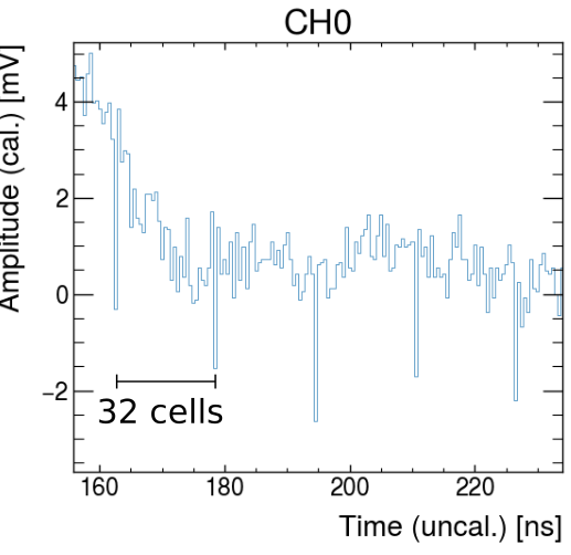
LynseyShun | Spikes/noise sensitive to clock settings? | Hello, I now have periodic spikes in CH0 and CH1 output. How can I eliminate these spikes? I'm sorry I didn't understand your elimination method. Please explain the method in detail. Thank you very much
| Stefan Ritt wrote: |
|
elog:824
| Sean Quinn wrote: |
|
Dear DRS4 team,
I'm trying to troubleshoot some odd spike behavior. If I run the ADC and SR CLK at 16 MHz (behavior also seen at 33 MHz) we get very noisy data (post-calibration) with periodic spikes.
In the below plot
- CH0 & CH1 are muon pulses from a scintillator + SiPM detector
- CH8 is a 25 MHz sinewave (in phase with all generated board clocks)
- Transparent mode = ON
- ROI = OFF, "full readout mode", first sample = cell 0
- DRS REFCLK = 1 MHz (2 GS/s)
- ADC & SR CLK = 16 MHz, 0 deg. offset

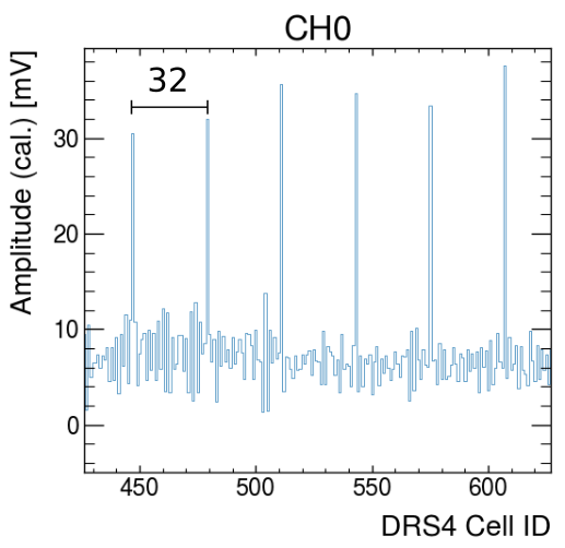
After I modify some clock settings, things seem to improve dramatically, and the spike behavior changes
- ADC and SR CLK = 15 MHz, 0 deg. offset
- Transparent mode = ON
- ROI = ON (just for testing purposes)
- Add 1.064 ns skew to DRS REF CLK
- NOTE: Unfortunately due to a design mishap, the ADC and FPGA clock use a phase-locked output pair on our clock synthesis chip, so we cannot fine-tune the skew for it.
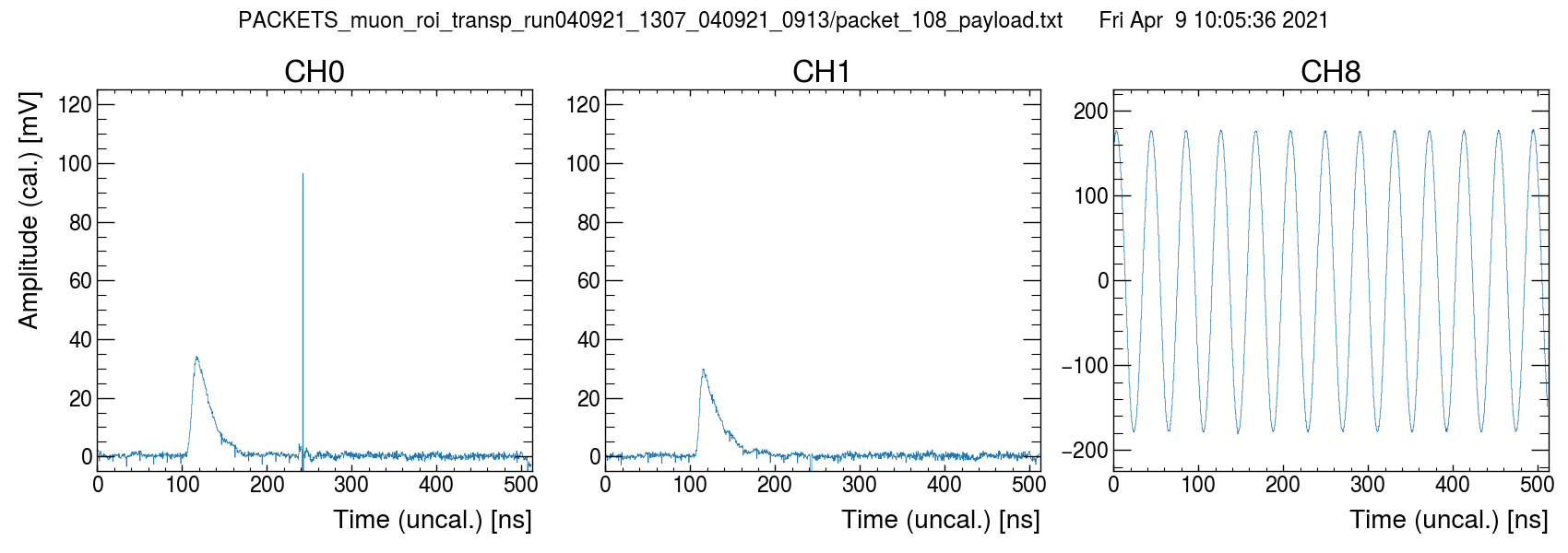
Observed differences
- Spike polarity seems inverted
- Spikes limited to smaller number of cells now?
- Spike amplitude reduced
- Overall baseline variance seems better
- New large positive spike artifact on CH0 that seems inverted on CH1
- CH8 seems unaffected by large spikes?
Artifacts seem related to clock configuration, but I am sort of in the dark on what might be happening from a first-principles point of view. Any tips?
Warm regards,
Sean
|
|
|
|
853
|
Thu Dec 23 03:42:26 2021 |
Lynsey | DRS4 request assistance | Dear Sir or Madam,
Good morning,I am using drs4 chip, and the measured fDTAP == 1/350ns, that is, fDOMINO == 1 / 350ns * 2048 == 5.8GHz.
I have three questions:
1. Is fDOMINO determined by the chip itself?
2. C1, C2 and R2 are TBD. I don't know how many to choose. Is there an algorithm?
3."Configure Write Shift Register to contain all 1's",What, pray, is the meaning of “1's"?
Truely yours.
|
|
854
|
Fri Dec 24 03:13:32 2021 |
Lynsey | Trouble getting PLL to lock | I also design the circuit myself. Our problem is the same. Can we communicate?
| Stefan Ritt wrote: |
|
I guess you mean "1 MHz clock at REFCLK+", and not CLKIN, there is no CLKIN, just a SRCLK, but that is someting else!
There could be many reasons why this is not working. It's hard for me to debug your board without actually having it in hands. So just some ideas:
- Supply a clean differential REFCLK, I never tried one end tied to VDD/2
- Is /RESET high?
- Is BIAS at roughly 0.7V?
- Is A0-A3 different from 1111, which puts the chip in standby
- Did you double check your loop filter?
The easiest usually is to start from a running evaluation board, then compare all pins 1:1 with your board.
Stefan
| Tom Schneider wrote: |
|
Hello,
I am working on a custom PCB design with the DRS4 chip, and I can't get the PLL to lock. I'm feeding CLKIN with a 1MHz CMOS clock (REFCLK- tied to VDD/2), and I'm using the same loop filter as the eval board. I see from the datasheet that the PLL is enabled by default, so I'm not writing anything to the config register on startup. I am just driving DENABLE high approx. 100ms after startup and looking for the PLL lock bit to go high. When I look at DTAP, I see a 3MHz signal. Can anyone tell me what I'm doing wrong?
-Tom
|
|
|
|
342
|
Tue May 13 19:34:58 2014 |
Luka Pavelic | drsosc binary to cern ROOT file conversion | Hi,
Does anybody have program for conversion from binary or xml to cern ROOT *.root file?
Thank you for any help you can provide,
Luka Pavelic
|
|
344
|
Tue May 13 22:03:47 2014 |
Luka Pavelic | drsosc binary to cern ROOT file conversion | Thank you for your fast and very helpful replay.
I made it work with drsosc version 4 but with version 5 i am getting weird results. Is it possible that they changed binary formatting?
|
|
737
|
Wed Feb 20 08:03:04 2019 |
Lev Pavlov | meg? | Hey. Strange problem. Why does the compiler refer there at all? Library installed drsosc works
LINK : fatal error LNK1104: cannot open file "C:\meg\online\drivers\drs\libusb-1.0\libusb-1.0.lib" |
|
739
|
Wed Feb 20 12:13:44 2019 |
Lev Pavlov | meg? | Great, drs_exam compiles without problems. Now when you run the compiled file drs_exam writes board not found, but drsosc and drscl work without problems. What could possibly be the matter?
thanks for your patience
Lev
| Stefan Ritt wrote: |
|
You have to change the path to libusb-1.0.lib to the one where you installed it.
Stefan
| Lev Pavlov wrote: |
|
Hey. Strange problem. Why does the compiler refer there at all? Library installed drsosc works
LINK : fatal error LNK1104: cannot open file "C:\meg\online\drivers\drs\libusb-1.0\libusb-1.0.lib"
|
|
|
|
742
|
Thu Feb 21 09:51:24 2019 |
Lev Pavlov | no board found | Hey. Yes, the program is running as administrator. By the way, this is win10. Your drs_exam works fine. My drs_exam compiled wrote no board found. Maybe this is a problem like in the post https://elog.psi.ch/elogs/DRS4+Forum/698. Maybe there were solutions to the problems?
Thank You
Lev
| Stefan Ritt wrote: |
|
No idea. Maye some access problem. Have you tried to start your program under an admin account?
Stefan
| Lev Pavlov wrote: |
|
Great, drs_exam compiles without problems. Now when you run the compiled file drs_exam writes board not found, but drsosc and drscl work without problems. What could possibly be the matter?
thanks for your patience
Lev
| Stefan Ritt wrote: |
|
You have to change the path to libusb-1.0.lib to the one where you installed it.
Stefan
| Lev Pavlov wrote: |
|
Hey. Strange problem. Why does the compiler refer there at all? Library installed drsosc works
LINK : fatal error LNK1104: cannot open file "C:\meg\online\drivers\drs\libusb-1.0\libusb-1.0.lib"
|
|
|
|
|
|
744
|
Mon Feb 25 08:40:44 2019 |
Lev Pavlov | no board found |
Hello. When compiling drs_exam, do you need to use a "static "version of usblib or a "dynamic" version?"The problem with "no board found" is not solved. Thanks for your help.
Lev.
| Stefan Ritt wrote: |
|
Could be. Have you tried that elog:657
Stefan
| Lev Pavlov wrote: |
|
Hey. Yes, the program is running as administrator. By the way, this is win10. Your drs_exam works fine. My drs_exam compiled wrote no board found. Maybe this is a problem like in the post https://elog.psi.ch/elogs/DRS4+Forum/698. Maybe there were solutions to the problems?
Thank You
Lev
| Stefan Ritt wrote: |
|
No idea. Maye some access problem. Have you tried to start your program under an admin account?
Stefan
| Lev Pavlov wrote: |
|
Great, drs_exam compiles without problems. Now when you run the compiled file drs_exam writes board not found, but drsosc and drscl work without problems. What could possibly be the matter?
thanks for your patience
Lev
| Stefan Ritt wrote: |
|
You have to change the path to libusb-1.0.lib to the one where you installed it.
Stefan
| Lev Pavlov wrote: |
|
Hey. Strange problem. Why does the compiler refer there at all? Library installed drsosc works
LINK : fatal error LNK1104: cannot open file "C:\meg\online\drivers\drs\libusb-1.0\libusb-1.0.lib"
|
|
|
|
|
|
|
|