| ID |
Date |
Author |
Subject |
|
383
|
Tue Oct 14 16:34:45 2014 |
Stephane Debieux | USB Microcontroller firmware |
| Stefan Ritt wrote: |
|
| Stephane Debieux wrote: |
|
| Stefan Ritt wrote: |
|
| Stephane Debieux wrote: |
|
| Stefan Ritt wrote: |
|
| Stephane Debieux wrote: |
|
Hi,
I'm trying to recompile the USB microcontroller firmware starting from the drs_eval.c file but I'm not able to get a .iic file close to the one provided with the eval board. It seems to me that this drs_eval.iic file does not match the drs_eval.c and drs_eval.hex files or that I'm doing something wrong. Could you please help or give me an explanation.
Thank you.
Stephane
|
I did not touch the firmware since a couple of years, but I can confirm that the drs_eval.iic is the correct firmware file, since we use this one on all of our boards. To program it, you need the Cypress USB Console. You remove the jumper (to detach the EEPROM), then power the board (which then boots from the internal memory), connect to the board via the Cypress console, the put back the jumper while the board is running, then program the file into the EEPROM.
Best,
Stefan
|
Thank you Stefan.
Would that be possible to get the corresponding drs_eval.c source file since I'm assuming the one provided with the eval board is not the right one?
Thank you.
Stephane
|
There is only one drs_eval.c version around, and I confirm that it is the one in the distribution. If you use different compiler settings, like optimisations, you might get a different executable file (and thus a .iic file), but the files have the same functionality.
Stefan
|
I'm very sorry to insist but if I take the .hex of the distribution, convert it to .iic using the hex2bix utility, and reprogram the board, I can't read the board correctly (invalid magic number read with drscl for instance). Also, when using the uVision2 project file you provide and compiling the drs_eval.c, I get the same result (i.e. no way to generate a functional .iic file starting from the sources). So, either I'm doing something wrong (and I don't know what) or the drs_eval.c is not the correct one.
|
And what happens if you program the .iic file from the distribution?
|
It works as expected. |
|
384
|
Tue Oct 14 16:38:14 2014 |
Stefan Ritt | USB Microcontroller firmware |
| Stephane Debieux wrote: |
|
| Stefan Ritt wrote: |
|
| Stephane Debieux wrote: |
|
| Stefan Ritt wrote: |
|
| Stephane Debieux wrote: |
|
| Stefan Ritt wrote: |
|
| Stephane Debieux wrote: |
|
Hi,
I'm trying to recompile the USB microcontroller firmware starting from the drs_eval.c file but I'm not able to get a .iic file close to the one provided with the eval board. It seems to me that this drs_eval.iic file does not match the drs_eval.c and drs_eval.hex files or that I'm doing something wrong. Could you please help or give me an explanation.
Thank you.
Stephane
|
I did not touch the firmware since a couple of years, but I can confirm that the drs_eval.iic is the correct firmware file, since we use this one on all of our boards. To program it, you need the Cypress USB Console. You remove the jumper (to detach the EEPROM), then power the board (which then boots from the internal memory), connect to the board via the Cypress console, the put back the jumper while the board is running, then program the file into the EEPROM.
Best,
Stefan
|
Thank you Stefan.
Would that be possible to get the corresponding drs_eval.c source file since I'm assuming the one provided with the eval board is not the right one?
Thank you.
Stephane
|
There is only one drs_eval.c version around, and I confirm that it is the one in the distribution. If you use different compiler settings, like optimisations, you might get a different executable file (and thus a .iic file), but the files have the same functionality.
Stefan
|
I'm very sorry to insist but if I take the .hex of the distribution, convert it to .iic using the hex2bix utility, and reprogram the board, I can't read the board correctly (invalid magic number read with drscl for instance). Also, when using the uVision2 project file you provide and compiling the drs_eval.c, I get the same result (i.e. no way to generate a functional .iic file starting from the sources). So, either I'm doing something wrong (and I don't know what) or the drs_eval.c is not the correct one.
|
And what happens if you program the .iic file from the distribution?
|
It works as expected.
|
Then why don't you use the .iic file and forget about the hex and c files? Honestly speaking, I don't remember what source file I compiled a couple of years ago, and it could be that an older file slipped into the repository, but that's all I have. I would have to investigate myself, try to compile and program the c file, do the debugging, and find out what the differences are. But unfortunately I don't have time for that right now. So just stick with the .iic file. |
|
385
|
Tue Oct 14 16:51:37 2014 |
Stephane Debieux | USB Microcontroller firmware |
| Stefan Ritt wrote: |
|
| Stephane Debieux wrote: |
|
| Stefan Ritt wrote: |
|
| Stephane Debieux wrote: |
|
| Stefan Ritt wrote: |
|
| Stephane Debieux wrote: |
|
| Stefan Ritt wrote: |
|
| Stephane Debieux wrote: |
|
Hi,
I'm trying to recompile the USB microcontroller firmware starting from the drs_eval.c file but I'm not able to get a .iic file close to the one provided with the eval board. It seems to me that this drs_eval.iic file does not match the drs_eval.c and drs_eval.hex files or that I'm doing something wrong. Could you please help or give me an explanation.
Thank you.
Stephane
|
I did not touch the firmware since a couple of years, but I can confirm that the drs_eval.iic is the correct firmware file, since we use this one on all of our boards. To program it, you need the Cypress USB Console. You remove the jumper (to detach the EEPROM), then power the board (which then boots from the internal memory), connect to the board via the Cypress console, the put back the jumper while the board is running, then program the file into the EEPROM.
Best,
Stefan
|
Thank you Stefan.
Would that be possible to get the corresponding drs_eval.c source file since I'm assuming the one provided with the eval board is not the right one?
Thank you.
Stephane
|
There is only one drs_eval.c version around, and I confirm that it is the one in the distribution. If you use different compiler settings, like optimisations, you might get a different executable file (and thus a .iic file), but the files have the same functionality.
Stefan
|
I'm very sorry to insist but if I take the .hex of the distribution, convert it to .iic using the hex2bix utility, and reprogram the board, I can't read the board correctly (invalid magic number read with drscl for instance). Also, when using the uVision2 project file you provide and compiling the drs_eval.c, I get the same result (i.e. no way to generate a functional .iic file starting from the sources). So, either I'm doing something wrong (and I don't know what) or the drs_eval.c is not the correct one.
|
And what happens if you program the .iic file from the distribution?
|
It works as expected.
|
Then why don't you use the .iic file and forget about the hex and c files? Honestly speaking, I don't remember what source file I compiled a couple of years ago, and it could be that an older file slipped into the repository, but that's all I have. I would have to investigate myself, try to compile and program the c file, do the debugging, and find out what the differences are. But unfortunately I don't have time for that right now. So just stick with the .iic file.
|
Thanks for the help.
I'm not doing this for fun, checking that the source matches the .iic ! I know I could directly use the .iic and forget about the hex and c files.
I just wanted to use your source file as the starting point for my own board, as everybody is doing at the application level. |
|
785
|
Thu May 21 07:38:05 2020 |
Keita Mizukoshi | Type check at DOFrame.h in official software | Hi,
I've failured to compile official software. The cause is the following line.
DOFrame.h L.111 bool GetRefclk() { return m_refClk > 0; }
m_refClk is pointer to bool. I guess these line is for null-check of the pointer.
Can I replace the following line as
bool GetRefclk() { return m_refClk != nullptr; }
?
The latest compilers may not accept C-style check.
My compiler version is
Apple clang version 11.0.3 (clang-1103.0.32.59)
Target: x86_64-apple-darwin19.4.0
Thread model: posix
InstalledDir: /Applications/Xcode.app/Contents/Developer/Toolchains/XcodeDefault.xctoolchain/usr/bin
Best regards,
Keita |
|
788
|
Fri May 22 13:24:51 2020 |
Stefan Ritt | Type check at DOFrame.h in official software | The software is a bit outdated, I will soon make a new release.
In meantime, you can replace that like with
bool GetRefclk(int board) { return m_refClk[board]; }
Best,
Stefan
| Keita Mizukoshi wrote: |
|
Hi,
I've failured to compile official software. The cause is the following line.
DOFrame.h L.111 bool GetRefclk() { return m_refClk > 0; }
m_refClk is pointer to bool. I guess these line is for null-check of the pointer.
Can I replace the following line as
bool GetRefclk() { return m_refClk != nullptr; }
?
The latest compilers may not accept C-style check.
My compiler version is
Apple clang version 11.0.3 (clang-1103.0.32.59)
Target: x86_64-apple-darwin19.4.0
Thread model: posix
InstalledDir: /Applications/Xcode.app/Contents/Developer/Toolchains/XcodeDefault.xctoolchain/usr/bin
Best regards,
Keita
|
|
|
811
|
Fri Feb 26 17:05:26 2021 |
Tom Schneider | Trouble getting PLL to lock | Hello,
I am working on a custom PCB design with the DRS4 chip, and I can't get the PLL to lock. I'm feeding CLKIN with a 1MHz CMOS clock (REFCLK- tied to VDD/2), and I'm using the same loop filter as the eval board. I see from the datasheet that the PLL is enabled by default, so I'm not writing anything to the config register on startup. I am just driving DENABLE high approx. 100ms after startup and looking for the PLL lock bit to go high. When I look at DTAP, I see a 3MHz signal. Can anyone tell me what I'm doing wrong?
-Tom |
|
812
|
Fri Feb 26 17:59:14 2021 |
Stefan Ritt | Trouble getting PLL to lock | I guess you mean "1 MHz clock at REFCLK+", and not CLKIN, there is no CLKIN, just a SRCLK, but that is someting else!
There could be many reasons why this is not working. It's hard for me to debug your board without actually having it in hands. So just some ideas:
- Supply a clean differential REFCLK, I never tried one end tied to VDD/2
- Is /RESET high?
- Is BIAS at roughly 0.7V?
- Is A0-A3 different from 1111, which puts the chip in standby
- Did you double check your loop filter?
The easiest usually is to start from a running evaluation board, then compare all pins 1:1 with your board.
Stefan
| Tom Schneider wrote: |
|
Hello,
I am working on a custom PCB design with the DRS4 chip, and I can't get the PLL to lock. I'm feeding CLKIN with a 1MHz CMOS clock (REFCLK- tied to VDD/2), and I'm using the same loop filter as the eval board. I see from the datasheet that the PLL is enabled by default, so I'm not writing anything to the config register on startup. I am just driving DENABLE high approx. 100ms after startup and looking for the PLL lock bit to go high. When I look at DTAP, I see a 3MHz signal. Can anyone tell me what I'm doing wrong?
-Tom
|
|
|
813
|
Fri Feb 26 18:33:52 2021 |
Tom Schneider | Trouble getting PLL to lock | Stefan,
Thanks for responding so quickly. Yes I have my clock source going to REFCLK+ (CLKIN is the signal name on my schematic). BIAS is 0.7V exactly, /RESET is high, A0-A3 are 0x0000, and the loop filter has a 4.7nF cap to GND with a 130ohm resistor + 1uF cap in parallel, just like the eval board.
Regarding the clock - I am not using an LVDS clock, but rather a 2.5V-level clock signal, with REFCLK- tied to 1.25V. Sheet 9 of the datasheet states: If no LVDS reference clock signal is available, a CMOS signal can be connected to REFCLK+ and the REFCLK input is connected to VDD/2 via a resistor divider.
Is that not a true statement?
-Tom
| Stefan Ritt wrote: |
|
I guess you mean "1 MHz clock at REFCLK+", and not CLKIN, there is no CLKIN, just a SRCLK, but that is someting else!
There could be many reasons why this is not working. It's hard for me to debug your board without actually having it in hands. So just some ideas:
- Supply a clean differential REFCLK, I never tried one end tied to VDD/2
- Is /RESET high?
- Is BIAS at roughly 0.7V?
- Is A0-A3 different from 1111, which puts the chip in standby
- Did you double check your loop filter?
The easiest usually is to start from a running evaluation board, then compare all pins 1:1 with your board.
Stefan
| Tom Schneider wrote: |
|
Hello,
I am working on a custom PCB design with the DRS4 chip, and I can't get the PLL to lock. I'm feeding CLKIN with a 1MHz CMOS clock (REFCLK- tied to VDD/2), and I'm using the same loop filter as the eval board. I see from the datasheet that the PLL is enabled by default, so I'm not writing anything to the config register on startup. I am just driving DENABLE high approx. 100ms after startup and looking for the PLL lock bit to go high. When I look at DTAP, I see a 3MHz signal. Can anyone tell me what I'm doing wrong?
-Tom
|
|
|
|
814
|
Fri Feb 26 20:32:25 2021 |
Stefan Ritt | Trouble getting PLL to lock | Can you post a scope trace of your refclk together with DTAP, DSPEED and DENABLE?
| Tom Schneider wrote: |
|
Stefan,
Thanks for responding so quickly. Yes I have my clock source going to REFCLK+ (CLKIN is the signal name on my schematic). BIAS is 0.7V exactly, /RESET is high, A0-A3 are 0x0000, and the loop filter has a 4.7nF cap to GND with a 130ohm resistor + 1uF cap in parallel, just like the eval board.
Regarding the clock - I am not using an LVDS clock, but rather a 2.5V-level clock signal, with REFCLK- tied to 1.25V. Sheet 9 of the datasheet states: If no LVDS reference clock signal is available, a CMOS signal can be connected to REFCLK+ and the REFCLK input is connected to VDD/2 via a resistor divider.
Is that not a true statement?
-Tom
| Stefan Ritt wrote: |
|
I guess you mean "1 MHz clock at REFCLK+", and not CLKIN, there is no CLKIN, just a SRCLK, but that is someting else!
There could be many reasons why this is not working. It's hard for me to debug your board without actually having it in hands. So just some ideas:
- Supply a clean differential REFCLK, I never tried one end tied to VDD/2
- Is /RESET high?
- Is BIAS at roughly 0.7V?
- Is A0-A3 different from 1111, which puts the chip in standby
- Did you double check your loop filter?
The easiest usually is to start from a running evaluation board, then compare all pins 1:1 with your board.
Stefan
| Tom Schneider wrote: |
|
Hello,
I am working on a custom PCB design with the DRS4 chip, and I can't get the PLL to lock. I'm feeding CLKIN with a 1MHz CMOS clock (REFCLK- tied to VDD/2), and I'm using the same loop filter as the eval board. I see from the datasheet that the PLL is enabled by default, so I'm not writing anything to the config register on startup. I am just driving DENABLE high approx. 100ms after startup and looking for the PLL lock bit to go high. When I look at DTAP, I see a 3MHz signal. Can anyone tell me what I'm doing wrong?
-Tom
|
|
|
|
|
815
|
Fri Feb 26 21:24:39 2021 |
Tom Schneider | Trouble getting PLL to lock | Probe capacitance makes that tricky - if I put my probe on DSPEED, I see that it starts at approx. 2.5V then gradually decreases until it hits 0V. DTAP decreases from 3MHz to 0 during this time.
I'll try to get something together to show you.
| Stefan Ritt wrote: |
|
Can you post a scope trace of your refclk together with DTAP, DSPEED and DENABLE?
| Tom Schneider wrote: |
|
Stefan,
Thanks for responding so quickly. Yes I have my clock source going to REFCLK+ (CLKIN is the signal name on my schematic). BIAS is 0.7V exactly, /RESET is high, A0-A3 are 0x0000, and the loop filter has a 4.7nF cap to GND with a 130ohm resistor + 1uF cap in parallel, just like the eval board.
Regarding the clock - I am not using an LVDS clock, but rather a 2.5V-level clock signal, with REFCLK- tied to 1.25V. Sheet 9 of the datasheet states: If no LVDS reference clock signal is available, a CMOS signal can be connected to REFCLK+ and the REFCLK input is connected to VDD/2 via a resistor divider.
Is that not a true statement?
-Tom
| Stefan Ritt wrote: |
|
I guess you mean "1 MHz clock at REFCLK+", and not CLKIN, there is no CLKIN, just a SRCLK, but that is someting else!
There could be many reasons why this is not working. It's hard for me to debug your board without actually having it in hands. So just some ideas:
- Supply a clean differential REFCLK, I never tried one end tied to VDD/2
- Is /RESET high?
- Is BIAS at roughly 0.7V?
- Is A0-A3 different from 1111, which puts the chip in standby
- Did you double check your loop filter?
The easiest usually is to start from a running evaluation board, then compare all pins 1:1 with your board.
Stefan
| Tom Schneider wrote: |
|
Hello,
I am working on a custom PCB design with the DRS4 chip, and I can't get the PLL to lock. I'm feeding CLKIN with a 1MHz CMOS clock (REFCLK- tied to VDD/2), and I'm using the same loop filter as the eval board. I see from the datasheet that the PLL is enabled by default, so I'm not writing anything to the config register on startup. I am just driving DENABLE high approx. 100ms after startup and looking for the PLL lock bit to go high. When I look at DTAP, I see a 3MHz signal. Can anyone tell me what I'm doing wrong?
-Tom
|
|
|
|
|
|
816
|
Fri Feb 26 22:12:58 2021 |
Stefan Ritt | Trouble getting PLL to lock | Sounds to me like your REFCLK is not getting through or your PLL loop is open. Could be a bad solder connection. Try to measure signals not on the PCB trace, but directly on the DRS4 pins. Drive REFCLK with a proper LVDS signal. Maybe it's wrong what I wrote in the data sheet and the trick with VDD/2 is not really working.
Stefan |
|
817
|
Fri Feb 26 22:52:13 2021 |
Tom Schneider | Trouble getting PLL to lock | Thats not a simple modification to my PCB, but I'll give it a try. Thanks for your help
| Stefan Ritt wrote: |
|
Sounds to me like your REFCLK is not getting through or your PLL loop is open. Could be a bad solder connection. Try to measure signals not on the PCB trace, but directly on the DRS4 pins. Drive REFCLK with a proper LVDS signal. Maybe it's wrong what I wrote in the data sheet and the trick with VDD/2 is not really working.
Stefan
|
|
|
818
|
Thu Mar 4 21:36:14 2021 |
Tom Schneider | Trouble getting PLL to lock | I found the problem, and it had nothing to do with the CMOS clock input. As it turns out, even though I was using the default state of the config register, I still had to write to it after powerup. Once I did that, the PLL locked immediately.
-Tom
| Tom Schneider wrote: |
|
Thats not a simple modification to my PCB, but I'll give it a try. Thanks for your help
| Stefan Ritt wrote: |
|
Sounds to me like your REFCLK is not getting through or your PLL loop is open. Could be a bad solder connection. Try to measure signals not on the PCB trace, but directly on the DRS4 pins. Drive REFCLK with a proper LVDS signal. Maybe it's wrong what I wrote in the data sheet and the trick with VDD/2 is not really working.
Stefan
|
|
|
|
819
|
Fri Mar 5 09:39:42 2021 |
Stefan Ritt | Trouble getting PLL to lock | That probably depends on the way your FPGA boots. If the SRCLK signal goes high after the SRIN - even a few ns - you might clock one or two zeros into the config register, thus disabling the PLL. Shame that I haven't thought of this before.
Stefan |
|
854
|
Fri Dec 24 03:13:32 2021 |
Lynsey | Trouble getting PLL to lock | I also design the circuit myself. Our problem is the same. Can we communicate?
| Stefan Ritt wrote: |
|
I guess you mean "1 MHz clock at REFCLK+", and not CLKIN, there is no CLKIN, just a SRCLK, but that is someting else!
There could be many reasons why this is not working. It's hard for me to debug your board without actually having it in hands. So just some ideas:
- Supply a clean differential REFCLK, I never tried one end tied to VDD/2
- Is /RESET high?
- Is BIAS at roughly 0.7V?
- Is A0-A3 different from 1111, which puts the chip in standby
- Did you double check your loop filter?
The easiest usually is to start from a running evaluation board, then compare all pins 1:1 with your board.
Stefan
| Tom Schneider wrote: |
|
Hello,
I am working on a custom PCB design with the DRS4 chip, and I can't get the PLL to lock. I'm feeding CLKIN with a 1MHz CMOS clock (REFCLK- tied to VDD/2), and I'm using the same loop filter as the eval board. I see from the datasheet that the PLL is enabled by default, so I'm not writing anything to the config register on startup. I am just driving DENABLE high approx. 100ms after startup and looking for the PLL lock bit to go high. When I look at DTAP, I see a 3MHz signal. Can anyone tell me what I'm doing wrong?
-Tom
|
|
|
|
636
|
Fri Nov 3 12:11:14 2017 |
H�kan Wennl�f | Triggering using AND | Hi!
I'm using the DRSOsc program, and I have a question that I need a bit clarified;
When triggering using AND between two channels, am I then triggering on rising/falling edge of both channels, or on the actual values?
That is, is it the change in value that it triggers on, or when the actual value goes above a certain threshold?
Using AND, it seems like I get a trigger when one (CH2) is above its trigger value (sometimes quite far above), and the other (CH1) changes to go above its trigger value. This works for my purposes, which is nice, but I just want to be sure I understand why it works. Ideally, I'd like to trigger when one of my channels is above a certain value, and the other has a rising edge above a certain value.
I'm sorry if it's a silly question! I've just noticed that the Keysight oscilloscopes I've used can only do one channel with a rising edge at a time when doing a logic trigger, and I thought the same thing might be going on in the background here (which would be ideal for my purposes).
Kind regards,
Håkan Wennlöf |
|
637
|
Fri Nov 3 13:28:04 2017 |
Stefan Ritt | Triggering using AND | Think about: How would you make a coincidence (AND) between two edges? Since an edge is infinitesimally small, there is no way to make a meaningful coincidence between edges. Therefore, the DRS4 EB firmware makes a simple AND of levels. If you trigger on rising signals and do an AND, then you get a trigger if both values are above their threshold. For falling edge trigger (arrow goes down in the trigger configuration) the board triggers when both signals are BELOW the trigger threshold. So actually the singnal which crosses the threshold last determines the timing of the trigger. I see no other way how to implement an AND.
Stefan
| Håkan Wennlöf wrote: |
|
Hi!
I'm using the DRSOsc program, and I have a question that I need a bit clarified;
When triggering using AND between two channels, am I then triggering on rising/falling edge of both channels, or on the actual values?
That is, is it the change in value that it triggers on, or when the actual value goes above a certain threshold?
Using AND, it seems like I get a trigger when one (CH2) is above its trigger value (sometimes quite far above), and the other (CH1) changes to go above its trigger value. This works for my purposes, which is nice, but I just want to be sure I understand why it works. Ideally, I'd like to trigger when one of my channels is above a certain value, and the other has a rising edge above a certain value.
I'm sorry if it's a silly question! I've just noticed that the Keysight oscilloscopes I've used can only do one channel with a rising edge at a time when doing a logic trigger, and I thought the same thing might be going on in the background here (which would be ideal for my purposes).
Kind regards,
Håkan Wennlöf
|
|
|
475
|
Thu Jan 14 21:49:37 2016 |
Chris Thompson | Triggering of DRS4 in the fastest sampling mode | I am attempting to use the DRS4 to measure the timing resolution of a pair of SensL silicon photomultipliers (SiPM). In order to do this I need to trigger the DRS4 only when there is a coincidence between the two input signals, and hopefully make histograms of the relative detection times of each detector.
There are two completely separate issues. (1) I think this may just be a labelling error. In the first image (OR_mode_selected) one can clearly see two pulses which are very similar. In this mode, both signals are present, and are always present. I think this should be the "AND", not "OR" of the two signals. Contrast this with the second image where I have selected "AND_mode". Clearly only one signal is present, and either signal trigges an event, so this should be "OR", not "AND"
The second issue is, for me, much more serious. I want to sample the leading edge of this event in order to determine its "time". The little "T" at the top of each image is, I believe the "trigger point" in the first two images. However, this is well after the part of the signal I am interested in. The first two images were at 2 GigaSamples/sec. The third is at 5 GigaSamples/sec. Clearly the event I am interested in processing is over by then. At the lower sampling rate, I can see well before the "T", but at the higher one I can only see after the "T". I had built an external "coincidence circuit" and the "external trigger mode" hoping to to circumvent this issue by using very long cables to delay the signals inut to the DRS4, But even then I have not been successful in getting the to work.
I am using version 5.0.3 on a PC as the version released after that did not work.
I hope some can help!
Chris Thompson |
| Attachment 1: OR_mode_selected.jpg
|

|
| Attachment 2: AND_mode_selected.jpg
|

|
| Attachment 3: 20ns_per_div.jpg
|

|
|
476
|
Fri Jan 15 08:09:00 2016 |
Stefan Ritt | Triggering of DRS4 in the fastest sampling mode | Hi Chris,
if you ever used an oscilloscope, you might be familar with the button controlling the riger in respect to "risign edge" vs. "falling edge". I copied the same for the DRS software. So just click on that button:
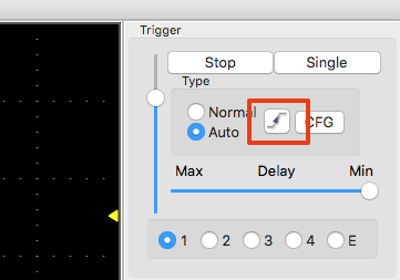
and you will get what you want. Also the AND/OR gets reversed this way. If you select rising edge (default), the AND will be made if both signals are ABOVE the threshold, that's why it does not work for you. If you select falling edge, the AND will be made if both signals are BELOW the threshold. For negative pulses you need falling edge.
Stefan
| Chris Thompson wrote: |
|
I am attempting to use the DRS4 to measure the timing resolution of a pair of SensL silicon photomultipliers (SiPM). In order to do this I need to trigger the DRS4 only when there is a coincidence between the two input signals, and hopefully make histograms of the relative detection times of each detector.
There are two completely separate issues. (1) I think this may just be a labelling error. In the first image (OR_mode_selected) one can clearly see two pulses which are very similar. In this mode, both signals are present, and are always present. I think this should be the "AND", not "OR" of the two signals. Contrast this with the second image where I have selected "AND_mode". Clearly only one signal is present, and either signal trigges an event, so this should be "OR", not "AND"
The second issue is, for me, much more serious. I want to sample the leading edge of this event in order to determine its "time". The little "T" at the top of each image is, I believe the "trigger point" in the first two images. However, this is well after the part of the signal I am interested in. The first two images were at 2 GigaSamples/sec. The third is at 5 GigaSamples/sec. Clearly the event I am interested in processing is over by then. At the lower sampling rate, I can see well before the "T", but at the higher one I can only see after the "T". I had built an external "coincidence circuit" and the "external trigger mode" hoping to to circumvent this issue by using very long cables to delay the signals inut to the DRS4, But even then I have not been successful in getting the to work.
I am using version 5.0.3 on a PC as the version released after that did not work.
I hope some can help!
Chris Thompson
|
|
|
621
|
Thu Jul 6 15:10:48 2017 |
Esperienza Giove | Trigger setting (AND AND) OR (AND AND) | Hello there,
is it possible to setup trigger in double AND configuration (a pair in and or other pair in and).
eg (CH 1 AND CH 2 ) OR ( CH 3 AND CH4)
Thank you |
|