| ID |
Date |
Author |
Subject |
|
561
|
Thu Nov 10 20:54:45 2016 |
Christian Farina | Missing Header | Hi Stefan,
I have already read the paper. I was just unsure where the calibration code was located. Thank you so much for all your help.
Christian
| Stefan Ritt wrote: |
|
Best is to read this paper: https://arxiv.org/abs/1405.4975
The source code for that is in DRS.cpp in the DRS software distribution in the function DRSBoard::CalibrateTiming()
Stefan
| Christian Farina wrote: |
|
Thank you Stefan, that was just what I needed.
Also, I have another question, if I am allowed to ask on this forum. I am trying to study how the time calibration of the DRS is done. Can you point me to the script in which this is done?
Thank you,
Christian
| Stefan Ritt wrote: |
|
The web page from where you downloaded the software contains a sentence "requires libusb-1.0 package". Please install it. This package brings the "usb.h" header file.
Stefan
| Christian Farina wrote: |
|
Hello everybody,
I am completely new to this, so please bear with me.
I am trying to install the applications on my laptop. I downloaded and untar-ed the drivers and applications for Linux as described in the evaluation board manual. However, when I do the make, I get the following error:
drs-4.0.0$ make
g++ -g -O2 -Wall -Wuninitialized -fno-strict-aliasing -Iinclude -DOS_LINUX -DHAVE_LIBUSB -DUSE_DRS_MUTEX -c src/musbstd.c
In file included from src/musbstd.c:14:0:
include/musbstd.h:17:17: fatal error: usb.h: No such file or directory
#include <usb.h>
Can anybody help me please?
Thanks.
|
|
|
|
|
|
560
|
Thu Nov 10 19:24:52 2016 |
Abhishek Rajput | Break Statements in DRS4 Binary to ROOT Macro | Hello,
I am wondering why the code should be changed to i < sizeof(eh), since doesn't fread(&eh,sizeof(eh),1,f) return 1 in this scenario? I've confirmed with a cout statement that this is the case, so this break condition will therefore always trigger as sizeof(eh) is 32 bytes.
Either way, I believe I figured out my problem. In my revised version of your code, I had two nested loops, the outer one being a loop over the channels and the inner one being a loop over the events. However, I really should have been doing the reverse considering the binary structure of the file. Otherwise, the end of the file will be reached for only a single iteration of the channel loop if I choose to loop through all the events in the data file.
Once I modified the code to have the outer loop be over all the events and the inner one be over all the channels, I no longer suffered from breaks in the loops.
Many thanks for your assistance.
Abhishek
| Stefan Ritt wrote: |
|
Hi,
fread() returns the number of bytes read and zero (I believe) if there is an end of file. So this break statement is a simple end-of-file test. There might be other erros such as hard disk failures, but these are extremely rare.
If course the file should not end in the middle of an event header. If it does, it means the file is corrupted and truncated, and we should not continue to read that file, that's why there is the break. The internal file is just a series of bytes, it does not know about the event header, so there will be no "error" if we have for example a missing event header but a voltage array. To be correct, the code should actually read
for (n=0 ; n<5 ; n++) {
      // read event header
      i = fread(&eh, sizeof(eh), 1, f);
      if (i < sizeof(eh))
         break;
Hope this helps,
Stefan
| Abhishek Rajput wrote: |
|
Hello,
I recently modified the binary to ROOT convertor written by Stefan (https://midas.psi.ch/elogs/DRS4+Forum/361) so it can decode data taken with any channel or set of channels on the DRS4. In the process of testing this modifed version for data taken on all 4 channels, I encountered problems with decoding some of the event data. More specifically, upon hitting a certain event in some channel, the histograms for that channel would no longer be filled and the histograms for subsequent channels would not be filled with any event at all.
After considerable bug hunting, I discovered the source of this problem was due to the break statement in the following code extract from the ROOT to binary macro:
 for (n=0 ; n<5 ; n++) {
      // read event header
      i = fread(&eh, sizeof(eh), 1, f);
      if (i < 1)
         break;
For some events apparently, the event header fails to be read properly (fread line returns 0 in this case). Moreover, when I used the feof and ferror functions on a particular file I was testing, the feof function returned a value of 1.
So my questions deal with two scenarios.
Firstly, in the event of an fread error, is a break statement is necessary? Is it not possible to skip the voltage data for those events whose event header fails to be read properly? Or is it the case that when some "corrupted" event header is encountered, all waveform data subsequent to that event is likewise corrupted? If the former is the case, is it advisable to replace the break condition with an fseek line that advances the position indicator of the stream by an additional 2052*n_channels + 32 bytes (in accordance with the binary file specifications of page 25 on the DRS4 manual) so that the next set of voltage data can be read?
Secondly, in the case of an end of file error, does there exist any possible solution? Or is such an error an indication of a faulty drs4 channel or corrupted binary file?
Any help with the aforementioned issues would be greatly appreciated.
Abhishek
|
|
|
|
558
|
Thu Nov 10 09:56:04 2016 |
Stefan Ritt | Break Statements in DRS4 Binary to ROOT Macro | Hi,
fread() returns the number of bytes read and zero (I believe) if there is an end of file. So this break statement is a simple end-of-file test. There might be other erros such as hard disk failures, but these are extremely rare.
If course the file should not end in the middle of an event header. If it does, it means the file is corrupted and truncated, and we should not continue to read that file, that's why there is the break. The internal file is just a series of bytes, it does not know about the event header, so there will be no "error" if we have for example a missing event header but a voltage array. To be correct, the code should actually read
for (n=0 ; n<5 ; n++) {
      // read event header
      i = fread(&eh, sizeof(eh), 1, f);
      if (i < sizeof(eh))
         break;
Hope this helps,
Stefan
| Abhishek Rajput wrote: |
|
Hello,
I recently modified the binary to ROOT convertor written by Stefan (https://midas.psi.ch/elogs/DRS4+Forum/361) so it can decode data taken with any channel or set of channels on the DRS4. In the process of testing this modifed version for data taken on all 4 channels, I encountered problems with decoding some of the event data. More specifically, upon hitting a certain event in some channel, the histograms for that channel would no longer be filled and the histograms for subsequent channels would not be filled with any event at all.
After considerable bug hunting, I discovered the source of this problem was due to the break statement in the following code extract from the ROOT to binary macro:
 for (n=0 ; n<5 ; n++) {
      // read event header
      i = fread(&eh, sizeof(eh), 1, f);
      if (i < 1)
         break;
For some events apparently, the event header fails to be read properly (fread line returns 0 in this case). Moreover, when I used the feof and ferror functions on a particular file I was testing, the feof function returned a value of 1.
So my questions deal with two scenarios.
Firstly, in the event of an fread error, is a break statement is necessary? Is it not possible to skip the voltage data for those events whose event header fails to be read properly? Or is it the case that when some "corrupted" event header is encountered, all waveform data subsequent to that event is likewise corrupted? If the former is the case, is it advisable to replace the break condition with an fseek line that advances the position indicator of the stream by an additional 2052*n_channels + 32 bytes (in accordance with the binary file specifications of page 25 on the DRS4 manual) so that the next set of voltage data can be read?
Secondly, in the case of an end of file error, does there exist any possible solution? Or is such an error an indication of a faulty drs4 channel or corrupted binary file?
Any help with the aforementioned issues would be greatly appreciated.
Abhishek
|
|
|
557
|
Thu Nov 10 04:41:24 2016 |
Abhishek Rajput | Break Statements in DRS4 Binary to ROOT Macro | Hello,
I recently modified the binary to ROOT convertor written by Stefan (https://midas.psi.ch/elogs/DRS4+Forum/361) so it can decode data taken with any channel or set of channels on the DRS4. In the process of testing this modifed version for data taken on all 4 channels, I encountered problems with decoding some of the event data. More specifically, upon hitting a certain event in some channel, the histograms for that channel would no longer be filled and the histograms for subsequent channels would not be filled with any event at all.
After considerable bug hunting, I discovered the source of this problem was due to the break statement in the following code extract from the ROOT to binary macro:
 for (n=0 ; n<5 ; n++) {
      // read event header
      i = fread(&eh, sizeof(eh), 1, f);
      if (i < 1)
         break;
For some events apparently, the event header fails to be read properly (fread line returns 0 in this case). Moreover, when I used the feof and ferror functions on a particular file I was testing, the feof function returned a value of 1.
So my questions deal with two scenarios.
Firstly, in the event of an fread error, is a break statement is necessary? Is it not possible to skip the voltage data for those events whose event header fails to be read properly? Or is it the case that when some "corrupted" event header is encountered, all waveform data subsequent to that event is likewise corrupted? If the former is the case, is it advisable to replace the break condition with an fseek line that advances the position indicator of the stream by an additional 2052*n_channels + 32 bytes (in accordance with the binary file specifications of page 25 on the DRS4 manual) so that the next set of voltage data can be read?
Secondly, in the case of an end of file error, does there exist any possible solution? Or is such an error an indication of a faulty drs4 channel or corrupted binary file?
Any help with the aforementioned issues would be greatly appreciated.
Abhishek
|
|
556
|
Wed Nov 9 19:49:07 2016 |
Stefan Ritt | Missing Header | Best is to read this paper: https://arxiv.org/abs/1405.4975
The source code for that is in DRS.cpp in the DRS software distribution in the function DRSBoard::CalibrateTiming()
Stefan
| Christian Farina wrote: |
|
Thank you Stefan, that was just what I needed.
Also, I have another question, if I am allowed to ask on this forum. I am trying to study how the time calibration of the DRS is done. Can you point me to the script in which this is done?
Thank you,
Christian
| Stefan Ritt wrote: |
|
The web page from where you downloaded the software contains a sentence "requires libusb-1.0 package". Please install it. This package brings the "usb.h" header file.
Stefan
| Christian Farina wrote: |
|
Hello everybody,
I am completely new to this, so please bear with me.
I am trying to install the applications on my laptop. I downloaded and untar-ed the drivers and applications for Linux as described in the evaluation board manual. However, when I do the make, I get the following error:
drs-4.0.0$ make
g++ -g -O2 -Wall -Wuninitialized -fno-strict-aliasing -Iinclude -DOS_LINUX -DHAVE_LIBUSB -DUSE_DRS_MUTEX -c src/musbstd.c
In file included from src/musbstd.c:14:0:
include/musbstd.h:17:17: fatal error: usb.h: No such file or directory
#include <usb.h>
Can anybody help me please?
Thanks.
|
|
|
|
|
555
|
Wed Nov 9 17:19:48 2016 |
Christian Farina | Missing Header | Thank you Stefan, that was just what I needed.
Also, I have another question, if I am allowed to ask on this forum. I am trying to study how the time calibration of the DRS is done. Can you point me to the script in which this is done?
Thank you,
Christian
| Stefan Ritt wrote: |
|
The web page from where you downloaded the software contains a sentence "requires libusb-1.0 package". Please install it. This package brings the "usb.h" header file.
Stefan
| Christian Farina wrote: |
|
Hello everybody,
I am completely new to this, so please bear with me.
I am trying to install the applications on my laptop. I downloaded and untar-ed the drivers and applications for Linux as described in the evaluation board manual. However, when I do the make, I get the following error:
drs-4.0.0$ make
g++ -g -O2 -Wall -Wuninitialized -fno-strict-aliasing -Iinclude -DOS_LINUX -DHAVE_LIBUSB -DUSE_DRS_MUTEX -c src/musbstd.c
In file included from src/musbstd.c:14:0:
include/musbstd.h:17:17: fatal error: usb.h: No such file or directory
#include <usb.h>
Can anybody help me please?
Thanks.
|
|
|
|
554
|
Tue Nov 8 10:20:52 2016 |
Stefan Ritt | Missing Header | The web page from where you downloaded the software contains a sentence "requires libusb-1.0 package". Please install it. This package brings the "usb.h" header file.
Stefan
| Christian Farina wrote: |
|
Hello everybody,
I am completely new to this, so please bear with me.
I am trying to install the applications on my laptop. I downloaded and untar-ed the drivers and applications for Linux as described in the evaluation board manual. However, when I do the make, I get the following error:
drs-4.0.0$ make
g++ -g -O2 -Wall -Wuninitialized -fno-strict-aliasing -Iinclude -DOS_LINUX -DHAVE_LIBUSB -DUSE_DRS_MUTEX -c src/musbstd.c
In file included from src/musbstd.c:14:0:
include/musbstd.h:17:17: fatal error: usb.h: No such file or directory
#include <usb.h>
Can anybody help me please?
Thanks.
|
|
|
553
|
Fri Nov 4 17:41:03 2016 |
Christian Farina | Missing Header | Hello everybody,
I am completely new to this, so please bear with me.
I am trying to install the applications on my laptop. I downloaded and untar-ed the drivers and applications for Linux as described in the evaluation board manual. However, when I do the make, I get the following error:
drs-4.0.0$ make
g++ -g -O2 -Wall -Wuninitialized -fno-strict-aliasing -Iinclude -DOS_LINUX -DHAVE_LIBUSB -DUSE_DRS_MUTEX -c src/musbstd.c
In file included from src/musbstd.c:14:0:
include/musbstd.h:17:17: fatal error: usb.h: No such file or directory
#include <usb.h>
Can anybody help me please?
Thanks. |
|
552
|
Fri Oct 28 15:51:59 2016 |
Stefan Ritt | Problems with DRS command line | No, I absolutely have no idea. Both DRSOsc and drscl use exaclty the same code to access USB.
Stefan
| Simon Mendisch wrote: |
that means, I am the second one experiencing this problem. To be more specific, the "No DRS Board found" problem is only present at one machine running Win7x64.
DRSOsc, of course not running simultaneously works just fine. Only drscl shows this behavior. Upgrading to a newer software version or a re-installation of the old one didn't solve the issue.
On other Win7x64 machines everything works fine, so I am pretty sure the problem is on this specific machine. Do you have any idea what could be the cause of this behavior?
|
|
|
551
|
Fri Oct 28 15:02:18 2016 |
Simon Mendisch | Problems with DRS command line |
| Stefan Ritt wrote: |
You are the first one describing this problem (out of ~200 people), so I guess the problem must be on your side. Have you made sure to start the DRS oscilloscope and the Command Line Interface not at the same time? Only one program can access the board at a given time. Have you tried disconnecting and re-connecting the board?
Stefan |
Hello,
that means, I am the second one experiencing this problem. To be more specific, the "No DRS Board found" problem is only present at one machine running Win7x64.
DRSOsc, of course not running simultaneously works just fine. Only drscl shows this behavior. Upgrading to a newer software version or a re-installation of the old one didn't solve the issue.
On other Win7x64 machines everything works fine, so I am pretty sure the problem is on this specific machine. Do you have any idea what could be the cause of this behavior?
Best Regards,
Simon |
|
550
|
Thu Oct 27 08:29:26 2016 |
Stefan Ritt | Problems with DRS command line |
| Alexey Lubinets wrote: | Hello, everybody
I have installed the software for the DRS4 Evaluation Board.
When I run the DRS Oscilloscope, it works OK (at least, my computer "knows", that the board is connected). But when I run the DRS Command Line Interface, it writes "USB successfully scanned, but no boards found
No DRS boards found".
How can I manage with this problem? The drivers for the DRS Evaluation Board are installed.
Regards, Alexey Lubinets |
You are the first one describing this problem (out of ~200 people), so I guess the problem must be on your side. Have you made sure to start the DRS oscilloscope and the Command Line Interface not at the same time? Only one program can access the board at a given time. Have you tried disconnecting and re-connecting the board?
Stefan |
|
549
|
Wed Oct 26 21:15:35 2016 |
Alexey Lubinets | Problems with DRS command line | Hello, everybody
I have installed the software for the DRS4 Evaluation Board.
When I run the DRS Oscilloscope, it works OK (at least, my computer "knows", that the board is connected). But when I run the DRS Command Line Interface, it writes "USB successfully scanned, but no boards found
No DRS boards found".
How can I manage with this problem? The drivers for the DRS Evaluation Board are installed.
Regards, Alexey Lubinets |
|
548
|
Tue Oct 11 22:11:26 2016 |
Stefan Ritt | time difference between 2 channels only ~30-35ps @ 5GSmples/s | Thank you very much! I will check it tomorrow!
-d
Concerning the offset, it looks to me like you moved the offset slider slider of channel 1 to a non-zero position. You see that from the marker at the very left side of the screen, where the yellow marker is at a different position as the others. Hint: a right-click on that slider sets it to zero. The little streak could be some kind of external noise.
| Danny Petschke wrote: |
|
Hello Stefan,
thanks for the paper. That makes sense. I thought about sth. like that but wasn`t sure. Couldn´t check higher frequencies (limit of my function generator).
What do think about the other picture I attached yesterday where Chn1 shows a totally different offset than Chn2-4. Moreover Chn4 shows some streaks (red circle) ?
Best regards
Danny
|
|
|
547
|
Tue Oct 11 09:20:04 2016 |
Stefan Ritt | time difference between 2 channels only ~30-35ps @ 5GSmples/s | Concerning the offset, it looks to me like you moved the offset slider slider of channel 1 to a non-zero position. You see that from the marker at the very left side of the screen, where the yellow marker is at a different position as the others. Hint: a right-click on that slider sets it to zero. The little streak could be some kind of external noise.
| Danny Petschke wrote: |
|
Hello Stefan,
thanks for the paper. That makes sense. I thought about sth. like that but wasn`t sure. Couldn´t check higher frequencies (limit of my function generator).
What do think about the other picture I attached yesterday where Chn1 shows a totally different offset than Chn2-4. Moreover Chn4 shows some streaks (red circle) ?
Best regards
Danny
|
|
|
546
|
Tue Oct 11 09:04:33 2016 |
Danny Petschke | time difference between 2 channels only ~30-35ps @ 5GSmples/s | Hello Stefan,
thanks for the paper. That makes sense. I thought about sth. like that but wasn`t sure. Couldn´t check higher frequencies (limit of my function generator).
What do think about the other picture I attached yesterday where Chn1 shows a totally different offset than Chn2-4. Moreover Chn4 shows some streaks (red circle) ?
Best regards
Danny
| Stefan Ritt wrote: |
|
Ok, I got it. The timing resolution is affected by the signal-to-noise ratio over the rise-time of your signal. You find the full formula herer:
https://arxiv.org/abs/1405.4975
Your sine wave input signal has a slow rise time, and therefore limits the time resolution. I reproduced your measurement with a 20 MHz sine wave and got the same result:
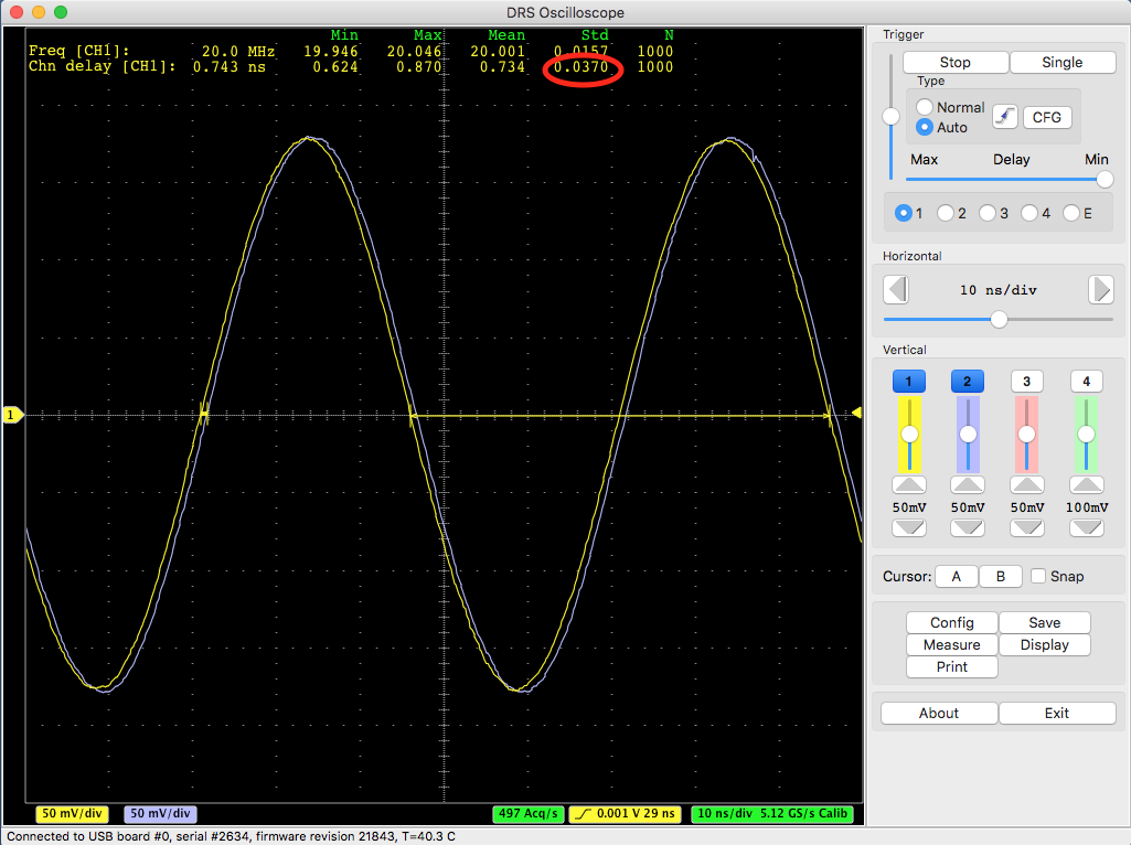
If I increase the frequency to 100 MHz and increase the amplitude, I get a better resolution:
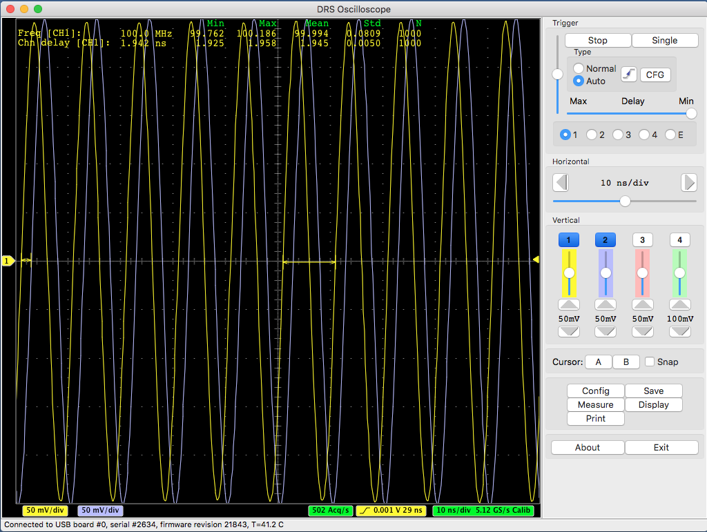
This is 5 ps which is better than 37 ps, but still not 2.5 ps. This can only be reached by sending single pulses to the evaluation board which have a rise time of > 300 mV / ns, which can be seen here:
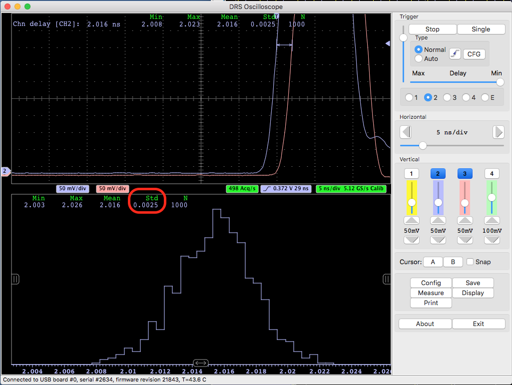
It is important to understand the relation timing - resolution vs. rise time / noise as explained in the quoted paper. If you have tiny pulses from your detector, you never will be able to measure excellent timing. This is physics, and not related to the specific electronics you are using.
Best regards,
Stefan
|
|
|
545
|
Mon Oct 10 12:03:27 2016 |
Stefan Ritt | time difference between 2 channels only ~30-35ps @ 5GSmples/s | Ok, I got it. The timing resolution is affected by the signal-to-noise ratio over the rise-time of your signal. You find the full formula herer:
https://arxiv.org/abs/1405.4975
Your sine wave input signal has a slow rise time, and therefore limits the time resolution. I reproduced your measurement with a 20 MHz sine wave and got the same result:
If I increase the frequency to 100 MHz and increase the amplitude, I get a better resolution:
This is 5 ps which is better than 37 ps, but still not 2.5 ps. This can only be reached by sending single pulses to the evaluation board which have a rise time of > 300 mV / ns, which can be seen here:
It is important to understand the relation timing - resolution vs. rise time / noise as explained in the quoted paper. If you have tiny pulses from your detector, you never will be able to measure excellent timing. This is physics, and not related to the specific electronics you are using.
Best regards,
Stefan
|
|
544
|
Mon Oct 10 11:30:37 2016 |
Danny Petschke | time difference between 2 channels only ~30-35ps @ 5GSmples/s | Hello Stefan,
Chn2 & Chn3 were used for delay-determination as you can see on the second picture.
The second picture shows all 4 Channels without any voltage input.
On Channel 4 streaks (red circle) occur often and Channel 1 has totally different Offset (Picture 1).
Thanks
| Stefan Ritt wrote: |
|
Can you post a screenshot of your measurement?
Stefan
| Danny Petschke wrote: |
|
(Board Type:9, DRS4)
Hello,
I´m trying to reach the timig resolution of about 2.5ps as written in the manual.
My settings are:
5GSamples/s
+/-0.5V
I followed the instructions of the manual. The chip was warm and ran about 10h. Then, Timing- followed by Voltage-Calibration.
The test-signal is a splittet sine-wave of 20MHz (function-generator) brought on A0 and A1 (A1 signal is delayed by 1ns-cable).
I´ve been testing different trigger-logic: (Chn1 AND Chn2), (Chn1 OR Chn2) and only Chn1 or Chn2.
Trigger-levels were changed too.
All setups show the same result of 1.009ns +/- 30-35ns (results from the DRS-Oscilloscope).
What is wrong from my side?
Thanks a lot for your help
|
|
|
|
543
|
Sun Oct 9 11:39:18 2016 |
Stefan Ritt | time difference between 2 channels only ~30-35ps @ 5GSmples/s | Can you post a screenshot of your measurement?
Stefan
| Danny Petschke wrote: |
|
(Board Type:9, DRS4)
Hello,
I´m trying to reach the timig resolution of about 2.5ps as written in the manual.
My settings are:
5GSamples/s
+/-0.5V
I followed the instructions of the manual. The chip was warm and ran about 10h. Then, Timing- followed by Voltage-Calibration.
The test-signal is a splittet sine-wave of 20MHz (function-generator) brought on A0 and A1 (A1 signal is delayed by 1ns-cable).
I´ve been testing different trigger-logic: (Chn1 AND Chn2), (Chn1 OR Chn2) and only Chn1 or Chn2.
Trigger-levels were changed too.
All setups show the same result of 1.009ns +/- 30-35ns (results from the DRS-Oscilloscope).
What is wrong from my side?
Thanks a lot for your help
|
|
|
542
|
Sun Oct 9 10:43:35 2016 |
Danny Petschke | time difference between 2 channels only ~30-35ps @ 5GSmples/s | (Board Type:9, DRS4)
Hello,
I´m trying to reach the timig resolution of about 2.5ps as written in the manual.
My settings are:
5GSamples/s
+/-0.5V
I followed the instructions of the manual. The chip was warm and ran about 10h. Then, Timing- followed by Voltage-Calibration.
The test-signal is a splittet sine-wave of 20MHz (function-generator) brought on A0 and A1 (A1 signal is delayed by 1ns-cable).
I´ve been testing different trigger-logic: (Chn1 AND Chn2), (Chn1 OR Chn2) and only Chn1 or Chn2.
Trigger-levels were changed too.
All setups show the same result of 1.009ns +/- 30-35ns (results from the DRS-Oscilloscope).
What is wrong from my side?
Thanks a lot for your help |
|
541
|
Thu Oct 6 15:23:18 2016 |
Will Flanagan | | Hi Stefan,
That is exactly what I'm looking for. Thanks again!
Will |
|