 Tue Jun 22 10:50:19 2010, Jinhong Wang, Reset of DRS4 Tue Jun 22 10:50:19 2010, Jinhong Wang, Reset of DRS4
|
Hi Stefan,
I found DRS draw a lot of current when applied Reset after power on, and the PLL does not work properly. I believe there was something that I misunderstood. So, what will happen when Reset is applied more than once after power on? . Though the chip worked well without a Reset, i want to try to find out what was wrong, for a better understanding of DRS.
best regards!
Jinhong |
 Tue Jun 22 11:02:30 2010, Stefan Ritt, Reset of DRS4 Tue Jun 22 11:02:30 2010, Stefan Ritt, Reset of DRS4
|
| Jinhong Wang wrote: |
|
Hi Stefan,
I found DRS draw a lot of current when applied Reset after power on, and the PLL does not work properly. I believe there was something that I misunderstood. So, what will happen when Reset is applied more than once after power on? . Though the chip worked well without a Reset, i want to try to find out what was wrong, for a better understanding of DRS.
best regards!
Jinhong
|
Have you made sure that DENABLE and DWRITE stays low during the reset? |
|
Tue Jun 22 11:29:26 2010, Jinhong Wang, Reset of DRS4
|
| Stefan Ritt wrote: |
|
| Jinhong Wang wrote: |
|
Hi Stefan,
I found DRS draw a lot of current when applied Reset after power on, and the PLL does not work properly. I believe there was something that I misunderstood. So, what will happen when Reset is applied more than once after power on? . Though the chip worked well without a Reset, i want to try to find out what was wrong, for a better understanding of DRS.
best regards!
Jinhong
|
Have you made sure that DENABLE and DWRITE stays low during the reset?
|
Yes, they are stay low until Reset goes high. the process is as following
Step1: Reset ='1', DEnable ='0', DWrite ='0', Reg_addr ="1111", Rsload='0', Srin ='0'
Step2: Reset='0', the others do not change, the low of the pulse is longer than 10 ns.
Step3: Reset='1', the others do not change, wait for some time
Step4: DEnable ='1' to start the domino. |
|
Tue Jun 22 11:35:18 2010, Stefan Ritt, Reset of DRS4
|
| Jinhong Wang wrote: |
|
| Stefan Ritt wrote: |
|
| Jinhong Wang wrote: |
|
Hi Stefan,
I found DRS draw a lot of current when applied Reset after power on, and the PLL does not work properly. I believe there was something that I misunderstood. So, what will happen when Reset is applied more than once after power on? . Though the chip worked well without a Reset, i want to try to find out what was wrong, for a better understanding of DRS.
best regards!
Jinhong
|
Have you made sure that DENABLE and DWRITE stays low during the reset?
|
Yes, they are stay low until Reset goes high. the process is as following
Step1: Reset ='1', DEnable ='0', DWrite ='0', Reg_addr ="1111", Rsload='0', Srin ='0'
Step2: Reset='0', the others do not change, the low of the pulse is longer than 10 ns.
Step3: Reset='1', the others do not change, wait for some time
Step4: DEnable ='1' to start the domino.
|
Ok, then I have no idea. I never tried several reset pulses (actually this is not needed), so I have to reproduce the problem myself and investigate it. Actually in all my designs the reset input is just left open, since the internal initial reset is enough, so I have to modify my design first... |
|
Tue Jun 22 11:37:42 2010, Jinhong Wang, Reset of DRS4
|
| Stefan Ritt wrote: |
|
| Jinhong Wang wrote: |
|
| Stefan Ritt wrote: |
|
| Jinhong Wang wrote: |
|
Hi Stefan,
I found DRS draw a lot of current when applied Reset after power on, and the PLL does not work properly. I believe there was something that I misunderstood. So, what will happen when Reset is applied more than once after power on? . Though the chip worked well without a Reset, i want to try to find out what was wrong, for a better understanding of DRS.
best regards!
Jinhong
|
Have you made sure that DENABLE and DWRITE stays low during the reset?
|
Yes, they are stay low until Reset goes high. the process is as following
Step1: Reset ='1', DEnable ='0', DWrite ='0', Reg_addr ="1111", Rsload='0', Srin ='0'
Step2: Reset='0', the others do not change, the low of the pulse is longer than 10 ns.
Step3: Reset='1', the others do not change, wait for some time
Step4: DEnable ='1' to start the domino.
|
Ok, then I have no idea. I never tried several reset pulses (actually this is not needed), so I have to reproduce the problem myself and investigate it. Actually in all my designs the reset input is just left open, since the internal initial reset is enough, so I have to modify my design first...
|
Ok ,thank you. |
|
Tue Sep 27 10:17:58 2022, Kunal Shinde, Required Firmware for DRS4 Evaluation Board Version 2.0
|
Hi, I am working on an old DRS4 board Version "2.0" with firmware revision "13191", I was unable to find this specific firmware source files ("VHDL source code"), please help me where could I find this or send me the required.
Regards,
Kunal |
|
Tue Sep 27 10:37:11 2022, Stefan Ritt, Required Firmware for DRS4 Evaluation Board Version 2.0
|
You find each software version at the usual download location at
https://www.dropbox.com/home/drs/drs4/distribution/Download/Linux
The one you need is probably drs-2.1.3.tar.gz which was the last version for the 2.0 board which is now more than 10 years old.
Best,
Stefan
| Kunal Shinde wrote: |
|
Hi, I am working on an old DRS4 board Version "2.0" with firmware revision "13191", I was unable to find this specific firmware source files ("VHDL source code"), please help me where could I find this or send me the required.
Regards,
Kunal
|
|
|
Tue Sep 27 10:52:41 2022, Kunal Shinde, Required Firmware for DRS4 Evaluation Board Version 2.0
|
I checked the link you provided but it seems that the link doesnt exist please send me valid one.
Regards,
Kunal
| Stefan Ritt wrote: |
|
You find each software version at the usual download location at
https://www.dropbox.com/home/drs/drs4/distribution/Download/Linux
The one you need is probably drs-2.1.3.tar.gz which was the last version for the 2.0 board which is now more than 10 years old.
Best,
Stefan
| Kunal Shinde wrote: |
|
Hi, I am working on an old DRS4 board Version "2.0" with firmware revision "13191", I was unable to find this specific firmware source files ("VHDL source code"), please help me where could I find this or send me the required.
Regards,
Kunal
|
|
|
|
Tue Sep 27 15:20:55 2022, Stefan Ritt, Required Firmware for DRS4 Evaluation Board Version 2.0
|
Sorry, got the wrong link. Here the right one: https://www.dropbox.com/sh/clqo7ekr0ysbrip/AACoWJzrQAbf3WiBJHG89bGGa?dl=0
If you untar the archive, you will find a "firmware" subdirectory with all VHDL code.
Stefan
| Kunal Shinde wrote: |
|
I checked the link you provided but it seems that the link doesnt exist please send me valid one.
Regards,
Kunal
| Stefan Ritt wrote: |
|
You find each software version at the usual download location at
https://www.dropbox.com/home/drs/drs4/distribution/Download/Linux
The one you need is probably drs-2.1.3.tar.gz which was the last version for the 2.0 board which is now more than 10 years old.
Best,
Stefan
| Kunal Shinde wrote: |
|
Hi, I am working on an old DRS4 board Version "2.0" with firmware revision "13191", I was unable to find this specific firmware source files ("VHDL source code"), please help me where could I find this or send me the required.
Regards,
Kunal
|
|
|
|
|
Wed Aug 7 15:05:59 2013, Hermann-Josef Mathes, Repeated time calibration
|
Hi,
is there any (obvious) reason why it is not possible (or not indended) to repeat the time calibration of a DRS4 eval board several times. I get the shown error message from the 'drscl' tool as well when I try to call the corresponding method in the support library:
mathes@ikauger5:~/src/DRS4> drs-4.0.1/drscl
DRS command line tool, Revision 20430
Type 'help' for a list of available commands.
Found DRS4 board 0 on USB, serial #2362, firmware revision 17662
B0> tcalib
Enter calibration frequency [GHz]: 5
Creating Timing Calibration of Board #2362
[==================================================]
B0> tcalib 5
Creating Timing Calibration of Board #2362
Error performing timing calibration, please check waveforms
As I will be in holidays, the answer is not urgent.
Thanks
-- Hermann-Josef
|
|
Wed Aug 7 15:10:57 2013, Stefan Ritt, Repeated time calibration
|
| Hermann-Josef Mathes wrote: |
|
Hi,
is there any (obvious) reason why it is not possible (or not indended) to repeat the time calibration of a DRS4 eval board several times. I get the shown error message from the 'drscl' tool as well when I try to call the corresponding method in the support library:
mathes@ikauger5:~/src/DRS4> drs-4.0.1/drscl
DRS command line tool, Revision 20430
Type 'help' for a list of available commands.
Found DRS4 board 0 on USB, serial #2362, firmware revision 17662
B0> tcalib
Enter calibration frequency [GHz]: 5
Creating Timing Calibration of Board #2362
[==================================================]
B0> tcalib 5
Creating Timing Calibration of Board #2362
Error performing timing calibration, please check waveforms
As I will be in holidays, the answer is not urgent.
Thanks
-- Hermann-Josef
|
Ups, this is certainly a bug. Try to restart drscl between calibrations. Anyhow the calibration is poor (~20ps), so in a month or two we will have a much better one (~3ps), but that needs a new board (then will be called V5).
/Stefan
|
|
Wed Aug 7 15:20:33 2013, Hermann-Josef Mathes, Repeated time calibration
|
| Stefan Ritt wrote: |
|
| Hermann-Josef Mathes wrote: |
|
Hi,
is there any (obvious) reason why it is not possible (or not indended) to repeat the time calibration of a DRS4 eval board several times. I get the shown error message from the 'drscl' tool as well when I try to call the corresponding method in the support library:
mathes@ikauger5:~/src/DRS4> drs-4.0.1/drscl
DRS command line tool, Revision 20430
Type 'help' for a list of available commands.
Found DRS4 board 0 on USB, serial #2362, firmware revision 17662
B0> tcalib
Enter calibration frequency [GHz]: 5
Creating Timing Calibration of Board #2362
[==================================================]
B0> tcalib 5
Creating Timing Calibration of Board #2362
Error performing timing calibration, please check waveforms
As I will be in holidays, the answer is not urgent.
Thanks
-- Hermann-Josef
|
Ups, this is certainly a bug. Try to restart drscl between calibrations. Anyhow the calibration is poor (~20ps), so in a month or two we will have a much better one (~3ps), but that needs a new board (then will be called V5).
/Stefan
|
Hi Stefan,
thanks for the quick reply, I know that this solution works with drscl but not within my code.
I tried to track it down, but gave up very soon. Seems as if AnalyzeWF() which is called by CalibrateTiming() finds to much zero-crossings when it is called the second time.
Regards
-- Hermann-Josef |
|
Wed Feb 5 13:41:42 2014, Stefan Ritt, Repeated time calibration
|
| Hermann-Josef Mathes wrote: |
|
Hi Stefan,
thanks for the quick reply, I know that this solution works with drscl but not within my code.
I tried to track it down, but gave up very soon. Seems as if AnalyzeWF() which is called by CalibrateTiming() finds to much zero-crossings when it is called the second time.
Regards
-- Hermann-Josef
|
Time calibration has been changed completely in meantime. With the new V5 boards, we have a new oscillator on the board where on can calibrate each channel individually. This is necessary to obtain a good timing down to a few ps. With the current code the above problem has vanished. We also learned that the time calibration is very stable (less than a ps) over several months, so no need to repeat the calibration over and over again.
/Stefan |
|
Wed Jun 1 09:57:43 2011, Martin Petriska, Removing spikes
|
I have DSR4 eval board. Found that there are spikes in channels. Procedure Osc::RemoveSpikes to remove them looks litlle dificult. There is simple way, if you doesnt need to measure all 4 channels.Spikes are in all channels, and it looks like they are same in time and value between channels. To remove them, if you are not using one channel, substract that unused channel with spikes from used channel and your data will be without spikes. If you need all 4 inputs, then may be channel 9 could be substracted. |
|
Thu Jun 2 21:01:29 2011, Stefan Ritt, Removing spikes
|
| Martin Petriska wrote: |
|
I have DSR4 eval board. Found that there are spikes in channels. Procedure Osc::RemoveSpikes to remove them looks litlle dificult. There is simple way, if you doesnt need to measure all 4 channels.Spikes are in all channels, and it looks like they are same in time and value between channels. To remove them, if you are not using one channel, substract that unused channel with spikes from used channel and your data will be without spikes. If you need all 4 inputs, then may be channel 9 could be substracted.
|
Indeed that's what I had before. If you don't need the 9th channels, you can use it to identify the spikes. But we have applications where we need all 9 channels. That's why I made Osc::RemoveSpikes a bit more complicated, so it will still work when all 9 channels are used. This new version is release 3.1.0. If you just blindly subtract the 9th channel, your noise could increase by a sqrt(2). |
|
Wed Sep 7 10:13:41 2022, Prajjalak Chattopadhyay, Register status after reset
|
What are the default register statuses after DRS4 gets reset? |
|
Tue Jan 25 14:15:00 2022, Thomas M., Regarding measuring for a set time
|
Hello,
I'm working on a project wherein we're looking at photomultipliers. We've already acquired a DRS4 evaluation board with the intent of using it to gather our data.
I've looked at the source code for the software with the intent of maybe writing a patch to add additional functionality. I was hoping you could answer some quick questions in that regard.
Am I correct in assuming that drsosc and drscl are functionally equivalent regarding collecting data? We want to run the DRS4-EB for a predefined amount of time. However, the DRS4 scope application seems only to run for a predefined set of measurements. Have I got that right? Is there some reason to avoid running the DRS4-EB for a predefined amount of time that I should be aware of?
Appreciate any help you can provide. Thanks!
Kind regards,
Thomas
|
|
Tue Jan 25 14:34:42 2022, Stefan Ritt, Regarding measuring for a set time
|
drsosc is a graphical application contiously acquiring data from the board, and drscl is a command line tool for debugging, as written in the manual.
The drsosc application runs indefinitely, but I guess you refer to saving data (by hitting the "Save" button in the drsosc application). Yes the save functionality has a number of events, since you cannot store data indefinitely, since your harddisk does not have indefinite space!
I kind of sense that you want to convert the "number of event to save" into "number of seconds or hours to save". This is not build into the drsosc application. It's all open source, so feel free to change the code. Alternatively, you can use the drs_exam.cpp program coming with the distribution, wich is a simpel C++ program reading the board. It has a for loop over 10 events, but you can change the code easily to run for a predetermined amount of time.
Stefan
| Thomas M. wrote: |
|
Am I correct in assuming that drsosc and drscl are functionally equivalent regarding collecting data? We want to run the DRS4-EB for a predefined amount of time. However, the DRS4 scope application seems only to run for a predefined set of measurements. Have I got that right? Is there some reason to avoid running the DRS4-EB for a predefined amount of time that I should be aware of?
|
|
|
Tue Jan 25 14:44:49 2022, Thomas M., Regarding measuring for a set time
|
Yes, you've got it exactly right. Thank you, that helps a lot!
Thomas
| Stefan Ritt wrote: |
|
drsosc is a graphical application contiously acquiring data from the board, and drscl is a command line tool for debugging, as written in the manual.
The drsosc application runs indefinitely, but I guess you refer to saving data (by hitting the "Save" button in the drsosc application). Yes the save functionality has a number of events, since you cannot store data indefinitely, since your harddisk does not have indefinite space!
I kind of sense that you want to convert the "number of event to save" into "number of seconds or hours to save". This is not build into the drsosc application. It's all open source, so feel free to change the code. Alternatively, you can use the drs_exam.cpp program coming with the distribution, wich is a simpel C++ program reading the board. It has a for loop over 10 events, but you can change the code easily to run for a predetermined amount of time.
Stefan
| Thomas M. wrote: |
|
Am I correct in assuming that drsosc and drscl are functionally equivalent regarding collecting data? We want to run the DRS4-EB for a predefined amount of time. However, the DRS4 scope application seems only to run for a predefined set of measurements. Have I got that right? Is there some reason to avoid running the DRS4-EB for a predefined amount of time that I should be aware of?
|
|
|
Tue May 18 09:24:02 2010, Stefan Ritt, Reference design for DRS4 active input buffer 
|
The design of high frequency differential input stages with the DRS4 is a challenge, since the chip draws quite some current at the input (up to 1 mA at 5 GSPS), which must be sourced by the input buffer. A simple transformer as used in the DRS4 Evaluation Board 2.0 limits the bandwidth to 220 MHz. In meantime two active input stages have been worked out and successfully been tested, both utilizing the THS4508 differential amplifier. The first design is AC-coupled and uses less power, the second design is DC-coupled and uses more power with the benefit of delivering a higher bandwidth.
Both designs use a clamping diode at the input as a protection against high voltage spikes at the input. We used a RCLAMP0502B diode from SEMTECH, but any fast voltage suppressor diode will do the job.
The CMOFS input to the THS4508 set the common mode of the differential amplifier. In the AC version the level is set to mid-rail (2.5V), in the DC version it's set to 1.8V to match the input range of the DRS4.
The CAL+ and CAL- signals are used to bias the inputs to a well-defined DC level and can also be used to calibrate the chip. For bipolar inputs, they are both set to 0.8V. A positive 0.5V input pulse then drives DRS_IN+ to (0.8+0.25)V = 1.05V and DRS_IN- to (0.8-0.25)V = 0.55V. A negative 0.5V pulse then drives then DRS_IN+ to 0.55V and DRS_IN- to 1.05V. With ROFS=1.6V, the full dynamic range of the DRS4 is then used. Note that the THS4508 has a gain of 2, and the input has a -6dB voltage divider to compensate for that. To use other input ranges, such as -1V...0V, the CAL+ and CAL- signals can be adjusted accordingly. Note that the inputs of the DRS4 must always be between 0.1V and 1.5V.
AC-coupled version
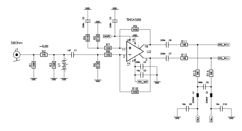
(click to enlarge)
Power supply: +5 V 40 mA
Bandwidth (-3dB): 600 MHz
CMOFS: 2.5 V
Transfer function:
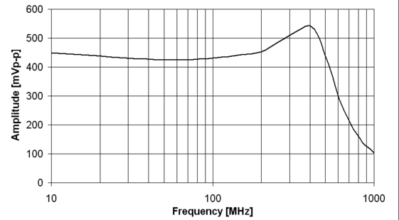
(click to enlarge)
The transfer function was measured by applying a fixed amplitude sine wave to the input, and measuring the peak-to-peak value of the read out waveform with the DRSOsc application.
DC-coupled Version
The DC-coupled version has a slightly higher power consumption since there is a constant current flowing through the output into the DRS4 chip. On the other hand, the bandwidth is a bit higher and the peaking around 400 MHz is a bit smaller. The input is still AC-coupled, so both positive and negative pulses can be accepted.
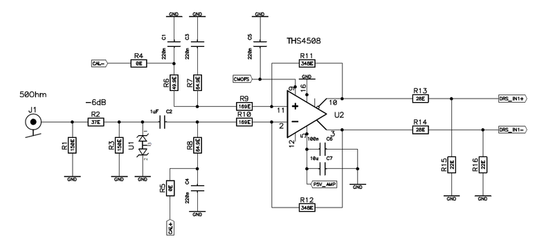
(click to enlarge)
Power supply: +5 V 115 mA
Bandwidth (-3dB): 800 MHz
CMOFS: 1.8 V
Transfer function:
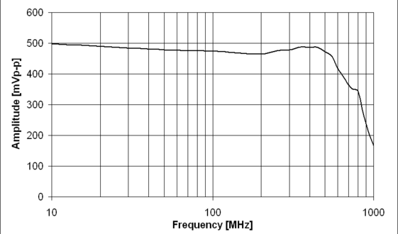
(click to enlarge)
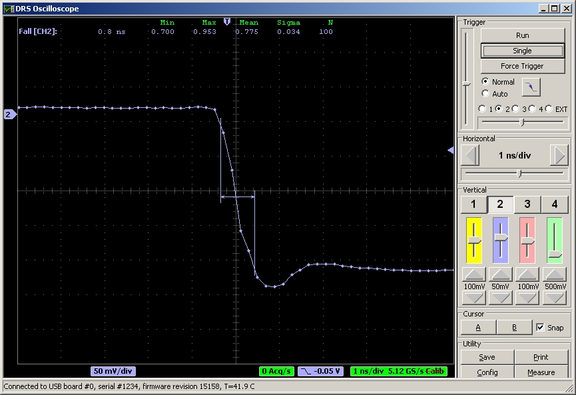
Achievable performance
With the active input stage, much faster rise- and fall times can be achieved. Following picture shows a signal from a external clock having a fall time of about 300 ps being recorded with the AC-coupled version of the active input stage. The fall time of the recorded signal is about 800 ps, which is about the minimum which can be achieved with the AC-coupled version. The DC-coupled version achieves about 700ps.
|
|