 Tue Oct 12 03:53:37 2010, Jinhong Wang, Reference design for DRS4 active input buffer Tue Oct 12 03:53:37 2010, Jinhong Wang, Reference design for DRS4 active input buffer
|
| Stefan Ritt wrote: |
|
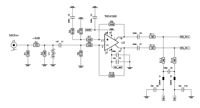
The design of high frequency differential input stages with the DRS4 is a challenge, since the chip draws quite some current at the input (up to 1 mA at 5 GSPS), which must be sourced by the input buffer. A simple transformer as used in the DRS4 Evaluation Board 2.0 limits the bandwidth to 220 MHz. In meantime two active input stages have been worked out and successfully been tested, both utilizing the THS4508 differential amplifier. The first design is AC-coupled and uses less power, the second design is DC-coupled and uses more power with the benefit of delivering a higher bandwidth.
Both designs use a clamping diode at the input as a protection against high voltage spikes at the input. We used a RCLAMP0502B diode from SEMTECH, but any fast voltage suppressor diode will do the job.
The CMOFS input to the THS4508 set the common mode of the differential amplifier. In the AC version the level is set to mid-rail (2.5V), in the DC version it's set to 1.8V to match the input range of the DRS4.
The CAL+ and CAL- signals are used to bias the inputs to a well-defined DC level and can also be used to calibrate the chip. For bipolar inputs, they are both set to 0.8V. A positive 0.5V input pulse then drives DRS_IN+ to (0.8+0.25)V = 1.05V and DRS_IN- to (0.8-0.25)V = 0.55V. A negative 0.5V pulse then drives then DRS_IN+ to 0.55V and DRS_IN- to 1.05V. With ROFS=1.6V, the full dynamic range of the DRS4 is then used. Note that the THS4508 has a gain of 2, and the input has a -6dB voltage divider to compensate for that. To use other input ranges, such as -1V...0V, the CAL+ and CAL- signals can be adjusted accordingly. Note that the inputs of the DRS4 must always be between 0.1V and 1.5V.
AC-coupled version
(click to enlarge)
Power supply: +5 V 40 mA
Bandwidth (-3dB): 600 MHz
CMOFS: 2.5 V
Transfer function:
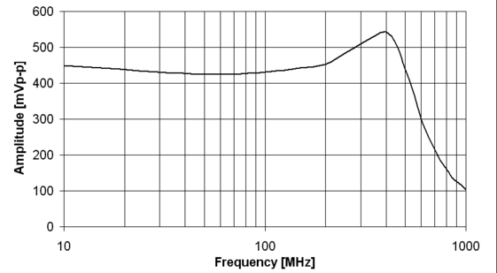
(click to enlarge)
The transfer function was measured by applying a fixed amplitude sine wave to the input, and measuring the peak-to-peak value of the read out waveform with the DRSOsc application.
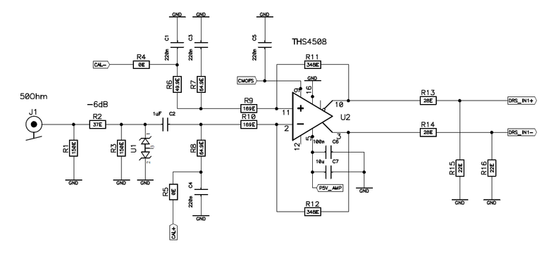
DC-coupled Version
The DC-coupled version has a slightly higher power consumption since there is a constant current flowing through the output into the DRS4 chip. On the other hand, the bandwidth is a bit higher and the peaking around 400 MHz is a bit smaller. The input is still AC-coupled, so both positive and negative pulses can be accepted.
(click to enlarge)
Power supply: +5 V 115 mA
Bandwidth (-3dB): 800 MHz
CMOFS: 1.8 V
Transfer function:
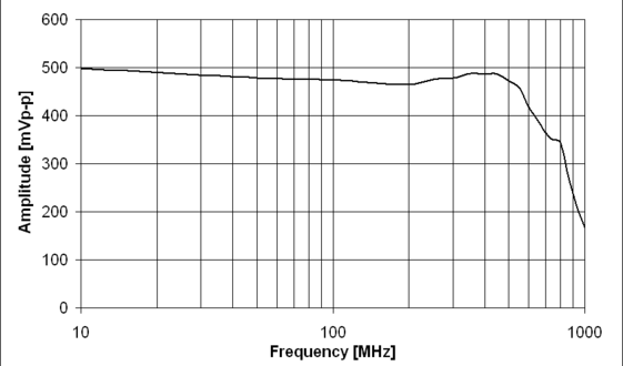
(click to enlarge)
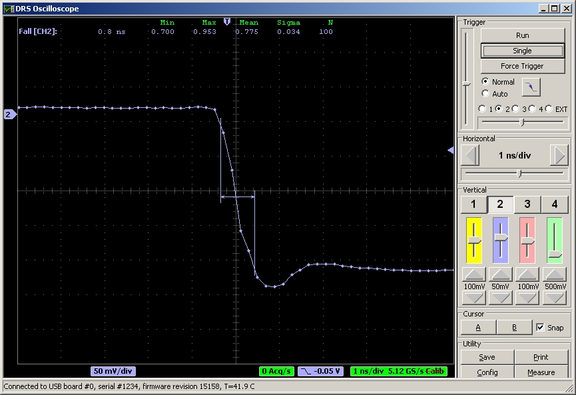
Achievable performance
With the active input stage, much faster rise- and fall times can be achieved. Following picture shows a signal from a external clock having a fall time of about 300 ps being recorded with the AC-coupled version of the active input stage. The fall time of the recorded signal is about 800 ps, which is about the minimum which can be achieved with the AC-coupled version. The DC-coupled version achieves about 700ps.
|
Hi, stefan,
In the DC coupled version of the analog drivers for DRS4 input in Eval. Board V3, you mentioned that CMOFS of THS4508 was set to 1.8V to match the input range of DRS4, however, will this clash with the requirements of DRS4 input voltage between 0.1 V ~1.5V ? The output of THS4508 can easily rise beyond 1.5V for CMOFS=1.8V. I also noticed the resister paris R13/R15, R14/R16 was added among the output of THS4508 and the inputs of DRS4, were these resister pairs were used to attenuate the level of THS4508 output signal (a half ? ) to match the input requirements of DRS4? Maybe I have some misunderstanding about it.
|
|
Tue Nov 16 16:38:06 2010, Stefan Ritt, Reference design for DRS4 active input buffer
|
| Jinhong Wang wrote: |
|
Hi, stefan,
In the DC coupled version of the analog drivers for DRS4 input in Eval. Board V3, you mentioned that CMOFS of THS4508 was set to 1.8V to match the input range of DRS4, however, will this clash with the requirements of DRS4 input voltage between 0.1 V ~1.5V ? The output of THS4508 can easily rise beyond 1.5V for CMOFS=1.8V. I also noticed the resister paris R13/R15, R14/R16 was added among the output of THS4508 and the inputs of DRS4, were these resister pairs were used to attenuate the level of THS4508 output signal (a half ? ) to match the input requirements of DRS4? Maybe I have some misunderstanding about it.
|
No you are right about that. The THS4508 has a gain of +2, and by using the resistor pairs we do
1) Reduce the gain back to unity
2) Reduce the input DC level from 1.8V to 0.9V to match the input range
3) Terminate the signals at the input of the DRS chip to minimize reflections
I know this is not so obvious from the schematic, so thanks for asking.
- Stefan |
 Sun Feb 21 13:41:35 2010, Stefan Ritt, Real Time Conference 2010 Sun Feb 21 13:41:35 2010, Stefan Ritt, Real Time Conference 2010
|
Hello,
may I draw your attention to the upcoming Real Time Conference 2010, taking place in Lisbon, Portugal, May 23rd to May 28th, 2010.
http://rt2010.ipfn.ist.utl.pt/
Several groups which are developing DRS4 electronics will come to this conference and present their work, so it will be a good opportunity to exchange ideas and experiences. There will also be a short course on digital pulse shape processing, which is highly relevant for our field.
Looking forward to see you in Lisbon,
Stefan |
|
Thu Mar 4 19:14:10 2010, Hao Huan, Readout of DRS Data
|
Hi Stefan,
thanks to your help I can now successfully keep the Domino wave running at a stable frequency and maintain the channel cascading information in the Write Shift Register. (Since you told me WSR always reads and writes at the same time, I think I need to rewrite the information back every time after reading out from WSR to decide from which channel my data come, don't I?)
However I'm still having difficulty in reading out from the DRS cells. I use the ROI readout mode and assume as long as I give a pulse on RSRLOAD the data will come out one by one. However, what I get is just a constant with some noise, which seems I'm always reading from the same cell. Actually I'm not very clear about how it works. What's the mechanism for RSRLOAD and do I have to initialize the Read Shift Register to use the ROI mode? Also I read in the datasheet that WSROUT will give RSR output when DWRITE is low. Sometimes I see some random bits from this output and sometimes I see all zero's. What is the reasonable output I should see from WSROUT, say, when I'm running in the transparent mode with DWRITE low?
Thank you very much!
|
|
Fri Mar 5 23:29:04 2010, Hao Huan, Readout of DRS Data
|
| Hao Huan wrote: |
|
Hi Stefan,
thanks to your help I can now successfully keep the Domino wave running at a stable frequency and maintain the channel cascading information in the Write Shift Register. (Since you told me WSR always reads and writes at the same time, I think I need to rewrite the information back every time after reading out from WSR to decide from which channel my data come, don't I?)
However I'm still having difficulty in reading out from the DRS cells. I use the ROI readout mode and assume as long as I give a pulse on RSRLOAD the data will come out one by one. However, what I get is just a constant with some noise, which seems I'm always reading from the same cell. Actually I'm not very clear about how it works. What's the mechanism for RSRLOAD and do I have to initialize the Read Shift Register to use the ROI mode? Also I read in the datasheet that WSROUT will give RSR output when DWRITE is low. Sometimes I see some random bits from this output and sometimes I see all zero's. What is the reasonable output I should see from WSROUT, say, when I'm running in the transparent mode with DWRITE low?
Thank you very much!
|
Hi Stefan,
I tried again and confirmed the problem... In the full readout mode I could successfully read out all the data, but in the ROI mode if I naively apply a pulse at RSRLOAD the results are not right. Is there anything I should be careful about in the ROI readout mode?
Thanks!
|
|
Thu Mar 11 11:45:52 2010, Stefan Ritt, Readout of DRS Data
|
| Hao Huan wrote: |
|
Hi Stefan,
thanks to your help I can now successfully keep the Domino wave running at a stable frequency and maintain the channel cascading information in the Write Shift Register. (Since you told me WSR always reads and writes at the same time, I think I need to rewrite the information back every time after reading out from WSR to decide from which channel my data come, don't I?)
|
Yes you do. But if you have WSRLOOP=1 in the config register, this is done automatically. So the SR output is visible at the pin and will be fed back into the input.
| Hao Huan wrote: |
|
However I'm still having difficulty in reading out from the DRS cells. I use the ROI readout mode and assume as long as I give a pulse on RSRLOAD the data will come out one by one.
|
That's not correct. Have a look at Figure 14 of the datasheet. Do you see a single RSRLOAD pulse or many? There is only one RSRLOAD pulse to initialize the readout shift register, then the cells are clocked by SRCLK pulses.
| Hao Huan wrote: |
|
Also I read in the datasheet that WSROUT will give RSR output when DWRITE is low. Sometimes I see some random bits from this output and sometimes I see all zero's. What is the reasonable output I should see from WSROUT, say, when I'm running in the transparent mode with DWRITE low?
|
A single RSRLOAD pulse loads the RSR with a "1" at the domino stop position and "0" in all other places. A pulse on SRCLK shifts this "1" down the RSR. When it arrives at cell #1023, it will be visible for one clock cycle at WSROUT. The "double" functionality of WSROUT has the following background: Assume you use channel cascading 2x2048. Now the domino wave stopps in cell 1020 of the first channel for example. You have to read cells 1020,1021,1022,1024 of the first channel, then you continue with 0,1,2 on the second channel. But how do you know that you have to switch channels after the first four clock cycles? The SROUT output encodes the stop position (in this case 1020), but it needs 10 clock cycles before the information is available, so you don't have it after four cycles. That's where WSROUT comes into play: Since it outputs RSR bit by bit, it will show three "0", then a "1", when you are at cell 1023. Then you know that you have to switch channels immediately. That's why I output RSR via WSROUT if DWRITE is low.
|
|
Thu Mar 22 14:36:01 2018, Phan Van Chuan, Read the CalibrateWaveform
|
Helo
I'm building an application for reading waveforms from the DRS4 board to PC. However, I am having problems reading calibration data from EEPROM on DRS4 board. The calibration data is read through the function reference:
void DRSBoard :: ReadCalibration (void)
...
ReadEEPROM (1, buf, 1024 * 32);
for (i = 0; i <8; i ++)
for (j = 0; j <1024; j ++) {
fCellOffset [i] [j] = buf [(i * 1024 + j) * 2];
fCellGain [i] [j] = buf [(i * 1024 + j) * 2 + 1] / 65535.0*0.4+0.7;
}
ReadEEPROM (2, buf, 1024 * 32);
for (i = 0; i <8; i ++)
for (j = 0; j <1024; j ++)
fCellOffset2 [i] [j] = buf [(i * 1024 + j) * 2];
...
The Calibrate Waveform is performed by:
int DRSBoard::CalibrateWaveform(unsigned int chipIndex, unsigned char channel, unsigned short *adcWaveform, short *waveform, bool responseCalib, int triggerCell, bool adjustToClock, float threshold, bool offsetCalib)
.....
for (j = 0; j < n_bins; j++) {
value = adcWaveform[j] - fCellOffset[channel+chipIndex*9][(j*skip + triggerCell) % kNumberOfBins];
value = value / fCellGain[channel+chipIndex*9][(j*skip + triggerCell) % kNumberOfBins];
if (offsetCalib && channel != 8)
value = value - fCellOffset2[channel+chipIndex*9][j*skip] + 32768;
...
. Because the calibration data reads incorrectly, the Calibrate Waveform does not do it.
Can read calibration data from EEPROM by any command via Oscilloscope application or DRS Command Line Interface application?
Thank you for your help!!!! |
|
Fri Mar 23 09:39:55 2018, Stefan Ritt, Read the CalibrateWaveform
|
You don't have to read and calibrate the waveforms in your user code, but can rely on the DRS.cpp library to do that. Just look at the drs_exam.cpp program coming with the distribution. It uses the function b->GetWave() to retrieve the calibrated waveform. If you like, you can look into that function to learn how to apply the calibration, but I can tell you that it's a bit complicated. Since each event starts at an arbitrary stop cell in the DRS4, you have to "rotate" the calibration array. Then you do actually four calibrations in a row (cell, readout, gain and range).
Stefan
| Phan Van Chuan wrote: |
|
Helo
I'm building an application for reading waveforms from the DRS4 board to PC. However, I am having problems reading calibration data from EEPROM on DRS4 board. The calibration data is read through the function reference:
void DRSBoard :: ReadCalibration (void)
...
ReadEEPROM (1, buf, 1024 * 32);
for (i = 0; i <8; i ++)
for (j = 0; j <1024; j ++) {
fCellOffset [i] [j] = buf [(i * 1024 + j) * 2];
fCellGain [i] [j] = buf [(i * 1024 + j) * 2 + 1] / 65535.0*0.4+0.7;
}
ReadEEPROM (2, buf, 1024 * 32);
for (i = 0; i <8; i ++)
for (j = 0; j <1024; j ++)
fCellOffset2 [i] [j] = buf [(i * 1024 + j) * 2];
...
The Calibrate Waveform is performed by:
int DRSBoard::CalibrateWaveform(unsigned int chipIndex, unsigned char channel, unsigned short *adcWaveform, short *waveform, bool responseCalib, int triggerCell, bool adjustToClock, float threshold, bool offsetCalib)
.....
for (j = 0; j < n_bins; j++) {
value = adcWaveform[j] - fCellOffset[channel+chipIndex*9][(j*skip + triggerCell) % kNumberOfBins];
value = value / fCellGain[channel+chipIndex*9][(j*skip + triggerCell) % kNumberOfBins];
if (offsetCalib && channel != 8)
value = value - fCellOffset2[channel+chipIndex*9][j*skip] + 32768;
...
. Because the calibration data reads incorrectly, the Calibrate Waveform does not do it.
Can read calibration data from EEPROM by any command via Oscilloscope application or DRS Command Line Interface application?
Thank you for your help!!!!
|
|
|
Mon Nov 17 16:36:18 2014, Mickey Chiu, Raspberry Pi drsosc does not exit properly
|
When running drsosc on a raspberry pi, it seems the exit doesn't seem to work at all. This is true for the "exit" button on the window, or the file menu exit, or the "x" on the window. I end up having to kill drsosc manually from the command line. This wouldn't be such a bad thing except that it doesn't seem to store any settings when killed in this way. I'm wondering if anyone else sees the same thing, or if there is a fix out there, before I go and delve into why. |
|
Tue Nov 25 14:06:34 2014, Stefan Ritt, Raspberry Pi drsosc does not exit properly
|
| Mickey Chiu wrote: |
|
When running drsosc on a raspberry pi, it seems the exit doesn't seem to work at all. This is true for the "exit" button on the window, or the file menu exit, or the "x" on the window. I end up having to kill drsosc manually from the command line. This wouldn't be such a bad thing except that it doesn't seem to store any settings when killed in this way. I'm wondering if anyone else sees the same thing, or if there is a fix out there, before I go and delve into why.
|
Unfortunately I don't have a pi here right now, so I cannot reproduce your problem. I checked on a linux system and it worked fine with wxWidgets 3.0.1 and GTK2 2.20. The wxWidget library sends an wxID_EXIT event to DOFrame::OnExit, which then closes the window. The destructor of DOFrame then calls SaveConfig() to save the current settings. Maybe you can debug this.
/Stefan |
|
Fri Oct 13 03:39:01 2017, Jonathan Wapman, Raspberry Pi Connection Failure
|
I am currently attempting to use a raspberry pi to connect to the DRS 4 board. I whenever I try to use the DRS Command Line TOol, Revision 21435 to connect to the drs board, I get the error
"musb_open: libusb_open() error -3"
"USB successfully scanned, but no boards found"
"No DRS Boards Found".
I successfully compiled the libusb driver before compiling the drs software 5.0.6, and installed all other listed packages in the install instructions. |
|
Mon Oct 16 15:35:22 2017, Stefan Ritt, Raspberry Pi Connection Failure
|
Have you tried as root? Maybe you miss some permissions.
Stefan
| Jonathan Wapman wrote: |
|
I am currently attempting to use a raspberry pi to connect to the DRS 4 board. I whenever I try to use the DRS Command Line TOol, Revision 21435 to connect to the drs board, I get the error
"musb_open: libusb_open() error -3"
"USB successfully scanned, but no boards found"
"No DRS Boards Found".
I successfully compiled the libusb driver before compiling the drs software 5.0.6, and installed all other listed packages in the install instructions.
|
|
|
Wed May 5 22:30:50 2010, Ignacio Di�guez Estremera, Random noise spec in datasheet
|
Hi,
According to DRS4's datasheet, the random noise is 0.35mVrms. Is this the input equivalent noise voltage? It is computed over the 0-950MHz frequency band?
Regards. |
|
Thu May 6 08:15:39 2010, Stefan Ritt, Random noise spec in datasheet
|
| Ignacio Diéguez Estremera wrote: |
|
Hi,
According to DRS4's datasheet, the random noise is 0.35mVrms. Is this the input equivalent noise voltage? It is computed over the 0-950MHz frequency band?
Regards.
|
You cannot compare the DRS4 noise directly with an amplifier for example. The noise mainly comes from variations of the charge injection into the storage cells, and some noise during the readout process, which happens in a completely different frequency domain than the sampling.
So what I did is to keep the inputs open, measure a 1024-bin waveform, and compute the RMS of this waveform. So I believe that this is kind of equivalent noise voltage from 1-950 MHz. It does not start from zero since very low frequency noise (like 50 Hz) just causes a baseline shift and does not influence the RMS, but this is not so important since in most applications people do an event-by-event baseline subtraction to get rid of low frequency noise in their apparatus. The 0.35 mV RMS also depend on the electronics around the chip. On our USB evaluation board the noise it typically smaller (0.31 mV RMS), while in some VME board we measure 0.42 mV RMS. If you do the perfect analog design around the chip, you can maybe push this maybe even lower. |
Tue Jun 18 14:19:39 2013, Stefan Ritt, ROOT program to decode binary data from DRSOsc 
|
Please find attached a simple ROOT based program (http://root.cern.ch) to decode binary data from the DRSOsc program. It assumes that all four channels were recorded. If this is not the case, the program can be adjusted accordingly.
To use it, simply type (assuming that you have written a data file "test.dat" with DRSOsc):
root [0] .L decode.C+
Info in <TUnixSystem::ACLiC>: creating shared library /tmp/./decode_C.so
root [1] decode("test");
Info in <TCanvas::MakeDefCanvas>: created default TCanvas with name c1
1927 events processed
"test.root" written
root [2]
If you have turned on the clock on channel4 of the DRS4 evaluation board, it will produce a plot like this:
/Stefan |
|
Wed Jul 30 17:05:06 2014, Stefan Ritt, ROOT program to decode binary data from DRSOsc
|
| Stefan Ritt wrote: |
|
Please find attached a simple ROOT based program (http://root.cern.ch) to decode binary data from the DRSOsc program. It assumes that all four channels were recorded. If this is not the case, the program can be adjusted accordingly.
To use it, simply type (assuming that you have written a data file "test.dat" with DRSOsc):
root [0] .L decode.C+
Info in <TUnixSystem::ACLiC>: creating shared library /tmp/./decode_C.so
root [1] decode("test");
Info in <TCanvas::MakeDefCanvas>: created default TCanvas with name c1
1927 events processed
"test.root" written
root [2]
If you have turned on the clock on channel4 of the DRS4 evaluation board, it will produce a plot like this:
/Stefan
|
I updated this ROOT program for the new format used with the V5 boards. It's now called "read_binary.C". Usage stays the same. There is also a standalone C program "read_binary.cpp". Both are attached. |
|
Fri Mar 8 19:35:11 2019, Abaz Kryemadhi, ROOT Macro for newest software
|
The older root macro did not work for me for data acquired with the newest software.
so for the newest software and multiple boards, I modified the read_binary.cpp into read_binary.C for those who like to use the root macro, see the attachment.
|
|
Tue Jan 29 14:43:44 2019, Abaz Kryemadhi, ROOT Macro for data acquired with the newest software
|
Hello,
Is there a root macro for decoding binary data acquired with the newest software for single board or multi-boards daisy chained?
Cheers,
Abaz |
|
Wed Jan 30 17:08:58 2019, Stefan Ritt, ROOT Macro for data acquired with the newest software
|
This one elog:361 should still work.
Stefan
| Abaz Kryemadhi wrote: |
|
Hello,
Is there a root macro for decoding binary data acquired with the newest software for single board or multi-boards daisy chained?
Cheers,
Abaz
|
|
|
Fri Mar 2 18:08:55 2018, Steven Block, ROI
|
Hello,
I have a question about how ROI works. From what I have read, it will only save data that ocurs some time [ta] dictated by the user after an event is triggered as well as a small time [tb] before the event. The technical manual seems to indicated that the deadtime assciated with operating in ROI mode can be reduced by the following factor:
 . .
Where N is the number of points in the time window (ex. 2048 or 1024). Is it ok to describe this as:

Where N' is the number of samples in the ROI and N is the same as before.
For example, if I were running at 5Gsps (200ps between samples), only recording 1024 samples per event and I had an signal that lasted 2ns, that means the signal would last 10 samples. If I set the ROI to only save 20 samples around this signal, would my Deadtime go to:
 ? (The second portion of this equation comes from a response I recieved earlier, but I just want to make sure I understand this concept properly) ? (The second portion of this equation comes from a response I recieved earlier, but I just want to make sure I understand this concept properly)
I recognize that the caveat is that this would work only if the signal was detected during acquistion, which leads to my next question. If no signals were detected in the 1024*200ps time frame in ROI mode, would the DRS4 go dead for 32us (using the factor = 1 from above equation), or would it dump the earliest events in the buffer for the more recent ones until it detects a signal?
Finally, I assume this functionality can only be utilized with custom electornics with the DRS4, not the evaulation/demo board, please let me know if this is the case.
Best,
Steven |
|