| ID |
Date |
Author |
Subject |
|
233
|
Fri Apr 5 08:54:37 2013 |
Stefan Ritt | cascading -- DRS4 Osci.cpp & DRS.cpp |
| Jill Russek wrote: |
|
Would it be possible to just hardcode a few lines in the SetChannelConfig in DRS.cpp method as such:
fChannelConfig = 0x01; //gives me eight
d = fChannelConfig | (fDominoMode << 8) | (1 << 9) | (fWSRLoop << 10) | (0xF8 << 8);
Write(T_CTRL, REG_CHANNEL_CONFIG, &d, 2);
fChannelDepth = 8 * (fDecimation ? kNumberOfBins/2 : kNumberOfBins);// gives eight times the bins
then modify the GetWave method/function to include another else if statement similar to "else if (fChannelCascading == 2) {" but would be modifidied for fChannelCascading == 8?
By, "But then you will hit the hard-wired limit in Osci.cpp" do you mean hard-coded? Would changing the hard code just amount to resizing all of the arrays, and replacing all the '2*kNumberBins" with '8*kNumberBins' ?
I'm afraid of drs_exam.cpp because it doesn't come with all the perks of Osci.cpp. It seems less daunting to just modify Osci.cpp then to try understanding everything I need to include in drs_exam.cpp because I'm also using an external trigger, and saving the waveform to an external text file.
Thanks!
/Jill
|
Sure it would be possible to code it, but it's not just a few lines. Besides Osci.cpp you have to massage DOScreen.cpp, Measurement.cpp and probably more since they all rely on the array size of the waveform. So if I would do it it would take me probably a couple of days including the debugging, which I don't have right now. Furthermore, as I said you have to combine all eight channels properly. For two channels, it's already pretty complicated (see lines 3537+ in DRS.cpp). I had to make myself a visual scheme in order to understand it correctly, which I attached. For eight channels, the write shift register (WSR) can have values 0-7, depending in which channel you got a trigger. Then you have to sort it out again to get one linear array with the proper order of the fragments. So you see, it's not just changing a few lines of code. In principle it's possible, but it's lots of work.
Best regards,
Stefan |
| Attachment 1: Screen_Shot_2013-04-05_at_8.51.53_.png
|

|
|
236
|
Thu Apr 11 08:39:12 2013 |
Stefan Ritt | cascading -- DRS4 Osci.cpp & DRS.cpp |
| Jill Russek wrote: |
|
| Stefan Ritt wrote: |
|
| Jill Russek wrote: |
|
Would it be possible to just hardcode a few lines in the SetChannelConfig in DRS.cpp method as such:
fChannelConfig = 0x01; //gives me eight
d = fChannelConfig | (fDominoMode << 8) | (1 << 9) | (fWSRLoop << 10) | (0xF8 << 8);
Write(T_CTRL, REG_CHANNEL_CONFIG, &d, 2);
fChannelDepth = 8 * (fDecimation ? kNumberOfBins/2 : kNumberOfBins);// gives eight times the bins
then modify the GetWave method/function to include another else if statement similar to "else if (fChannelCascading == 2) {" but would be modifidied for fChannelCascading == 8?
By, "But then you will hit the hard-wired limit in Osci.cpp" do you mean hard-coded? Would changing the hard code just amount to resizing all of the arrays, and replacing all the '2*kNumberBins" with '8*kNumberBins' ?
I'm afraid of drs_exam.cpp because it doesn't come with all the perks of Osci.cpp. It seems less daunting to just modify Osci.cpp then to try understanding everything I need to include in drs_exam.cpp because I'm also using an external trigger, and saving the waveform to an external text file.
Thanks!
/Jill
|
Sure it would be possible to code it, but it's not just a few lines. Besides Osci.cpp you have to massage DOScreen.cpp, Measurement.cpp and probably more since they all rely on the array size of the waveform. So if I would do it it would take me probably a couple of days including the debugging, which I don't have right now. Furthermore, as I said you have to combine all eight channels properly. For two channels, it's already pretty complicated (see lines 3537+ in DRS.cpp). I had to make myself a visual scheme in order to understand it correctly, which I attached. For eight channels, the write shift register (WSR) can have values 0-7, depending in which channel you got a trigger. Then you have to sort it out again to get one linear array with the proper order of the fragments. So you see, it's not just changing a few lines of code. In principle it's possible, but it's lots of work.
Best regards,
Stefan
|
Stefan, thanks for your help so far. If I go with your plan A of just modifying drs_exam.cpp, is there a quick way to get it to save the data from the wave, like how osci.cpp spits out an xml file? (Ignoring the cascading aspect for now)
Thanks again :)
/Jill
|
Well, you have to learn C programming, I won't do it for you. drs_exam.cpp contains already code to write to the ASCII file data.txt, so you just can use that or modify it to your needs.
/Stefan |
|
239
|
Fri Apr 12 08:25:05 2013 |
Stefan Ritt | cascading -- DRS4 Osci.cpp & DRS.cpp |
| Jill Russek wrote: |
|
| Stefan Ritt wrote: |
|
| Jill Russek wrote: |
|
Stefan, thanks for your help so far. If I go with your plan A of just modifying drs_exam.cpp, is there a quick way to get it to save the data from the wave, like how osci.cpp spits out an xml file? (Ignoring the cascading aspect for now)
Thanks again :)
/Jill
|
Well, you have to learn C programming, I won't do it for you. drs_exam.cpp contains already code to write to the ASCII file data.txt, so you just can use that or modify it to your needs.
/Stefan
|
Ha! So then the answer is no, there isn't a ready made function/method to pull out the timing and voltage, like how it was done in osci.cpp. That's all I wanted to know. (Not whether you would write it for me! Only trying to save time!) Thanks!
/Jill
|
You misunderstood. The answer is yes. drs_exam.cpp contains already code to write to an ASCII file. If you actually look into the file, you see:
f = fopen("data.txt", "w");
...
b->GetTime(0, b->GetTriggerCell(0), time_array);
...
b->GetWave(0, 0, wave_array[0]);
...
fprintf(f, "%5.2f %6.2f\n", time_array[i], wave_array[0][i]);
which actually pulls out the timing and voltage and writes it to the file. |
|
240
|
Fri Apr 12 08:38:17 2013 |
Stefan Ritt | code/details for optimal DRS4 timing calibration? |
| Bill Ashmanskas wrote: |
|
Hi Stefan,
Is either some example code or a detailed written description available for the improved DRS4 timing-calibration algorithm described by Daniel Stricker-Shaver at MIC 2012? I think you told me that you had verified the results with your own test set-up, so I figure there must be at least two sets of code in existence to implement this calibration. (I have Daniel's presentation slides.)
I managed to find a ping-pong distribution of cell widths that looks quite similar to that shown in Daniel's slides, using an algorithm similar to the technique one uses to find radial offsets in a tracking chamber (i.e. using residuals weighted by track slope), but I'd rather use the method with which you and Daniel have already found good results. (The attached graph shows in black the histogram of cell widths for essentially the algorithm used in DRS.cpp/DRSBoard::AnalyzeWF, and in blue the histogram of cell widths extracted from the slope-weighted residuals for a periodic reference signal.)
By the way, since Daniel finds a FWHM coincidence-timing resolution around 20-25ps at 5 GSPS (for perfectly identical pulses), should I expect a FWHM resolution (for synthesized, ideal pulses) of around 50-65ps at 2 GSPS?
(I'm posting here instead of writing you both privately because I figure there may be broader interest in Daniel's algorithm.)
-Bill
|
Hi Bill,
there are several reasons why we have not yet published Daniel's method (I'm in constant contact with him).
1. The method still changes, becomes simpler and more accurate. Originally he used sine waves with varying frequency, which you only get from an external function oscillator. Currently, we found that a single frequency could do a similar, maybe even better job. The current result is much better than the 20-25ps quoted at MIC 2012.
2. Daniel found out that for the ultimate resolution you have to calibrate each channel inside a chip separately. I do understand in meantime the reason for that. So I plan for a V5 evaluation board, which contains means of sending a log-jitter clock to all channels. This board is in test phase and will be made available once it's working as expected.
So my plan is to finish the V5 board and implement the best possible timing calibration on it. Daniel achieved already <5 ps RMS (!) independent of the delay between the two optimal pulses (up to 50 ns). This is actually better than what you can do with a high-end oscilloscope, since scopes have internal interleaving and similar problems due to aliasing etc. than the DRS chip, but scope manufacturers do not put such an emphasis on accurate timing measurements. Once we can reproduce the 5 ps result with the evaluation board, we will publish it. When we found the optimal method, we plan to write a paper about it and explain everything in great detail. We will also be at Seoul for MIC 2013. I'm topic convener there for the session "Digitalization, Acquisition, and Signal Processing Technologies". So probably we will put the DRS4 timing talk there, since it's of more general interest not only to medical applications (and honestly, for a 150 ps TOF-PET you do not need a 5 ps electronics resolution). So stay tuned!
/Stefan |
|
242
|
Mon Apr 22 15:52:53 2013 |
Stefan Ritt | effect of jitter/alignment between SRCLK and ADC clock |
| Benjamin LeGeyt wrote: |
|
Hello!
let me apologize in advance if this has already been covered somewhere and I missed it.
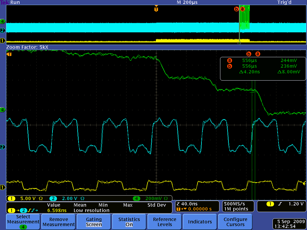
I have a question about a statement made regarding the ADC clock in the evaluation board v4.0 manual. At the bottom or page 23 there is a mention of jitter between the SRCLK signal and the ADC clock causing a baseline variation in the sampled output of up to a few mV. Is there any more information out there about this? I find this confusing for the following reason: If the DRS output has mostly settled after 28ns and the signal that is being sampled is a DC signal, I don't understand why an aperture jitter in the sampling ADC should cause a voltage error in the measured signal. I already know about the possibility of noise spikes every 32 samples if these clocks are not properly aligned, though I don't know the origin of those spikes. are these two things related?
Many Thanks!
|
Hi Benjamin,
In principle you are right, for a DC signal that should not matter. But in reality the DRS4 output signal is not constant even for a DC signal. When you switch from one sampling cell to another during readout, there is something called "charge injection". This causes the output to change up to several 10 mV. After 28 ns this is mostly settled, but not completely, since the DRS4 output driver has a relatively low bandwidth (~50 MHz). Furthermore, the signal line between the DRS4 and the ADC is not terminated, so you have some reflections going forth and back. In addition, you have some crosstalk from the SRCLK signal. So it's better that you sample on each cycle at exactly the same time. Here you see a plot of that (green: DRS4 output, blue: ADC clock, yellow SRCLK):
|
|
247
|
Tue May 21 13:25:41 2013 |
Stefan Ritt | mac osx 10.6 | > Hi,
>
> I would like to use the DRS4 with my macbook pro running osx 10.6.8.
> I have installed the wxWidgets and the libusb-1.0 libraries and I am using the Linux code vers. 4.0.1. After
> compilation, the following errors come out:
>
> ld: warning: in musbstd.o, file was built for unsupported file format which is not the architecture being linked
> (i386)
> ld: warning: in mxml.o, file was built for unsupported file format which is not the architecture being linked (i386)
> ....
> ....
> ld: warning: in main.o, file was built for unsupported file format which is not the architecture being linked (i386)
> Undefined symbols:
> "_main", referenced from:
> start in crt1.10.6.o
> ld: symbol(s) not found
> collect2: ld returned 1 exit status
> make: *** [drsosc] Error 1
>
>
> Do you have any idea on how to solve the problem ?? or maybe do you have a package working with osx 10.6 ? I
> remember to have seen, long time ago, a package that could work with 10.6 (or 10.5 ?), but I cannot find it now
> (but maybe I remember wrong).
>
> Thanks for any help,
>
> Enrico
Can it be that you have a old PowerPC MAC? I have no experience with that, but probably you have to adjust the Makefile
ans set some flags correctly for PPC instead of Intel.
/Stefan |
|
251
|
Tue May 21 17:51:09 2013 |
Stefan Ritt | mac osx 10.6 | > >
> > it looks like 64bit vs 32bit problem, you have to compile all libraries for the same architecture. Maybe, make clean to
> > remove all precompiled object files .o and recompile it again. Try to compile first that simple example without wxWidgets.
> >
> > Martin
>
>
> Good point, but all libraries are already compiled to 32 bits, since the laptop is running at 32 bits. Unless you mean that I
> have to convert to 64 bits, but this means to change all content of the PC, and I don't want to do this. Can the applications
> run with 32 bits or do they need 64 ?
>
> Thanks,
> Enrico
There is no specific reason to run it on 64 bits, so just all libraries have to match, that's all. But the original Makefile has been written for 64 bits, so it might need some
adjustments.
/Stefan |
|
254
|
Fri May 24 18:20:14 2013 |
Stefan Ritt | mac osx 10.6 | > I made some progress. Understood what was wrong in the make phase. You have only to add the option -arch i386 in the CFLAGS line of the makefile.
> Then the make is ok, it produces the 3 executables. drs_exam and drscl seem to work correctly.
> DRSOsc.app does not work as app, in the sense that if you click it, an error message comes saying "You can't use this version of the application DRSOsc.app with
> this version of Mac OS X. You have Mac OSX 10.6.8. The application requires Mac OS X 10.7 or later. "
> If you execute drsosc from the terminal, the graphical window pops up, the waveform is displayed, but you don't have access to the graphical interface, no button works, you can't do
> anything. To quit the app, you have to kill it from the terminal with the kill command.
To run an executable as an app, you have to put it into a certain directory structure. The Makefile has the target "make app" which exactly does that. It executes following code:
DRSOsc.app: drsosc
-mkdir DRSOsc.app
-mkdir DRSOsc.app/Contents
-mkdir DRSOsc.app/Contents/MacOS
-mkdir DRSOsc.app/Contents/Resources
-mkdir DRSOsc.app/Contents/Resources/English.lproj
echo 'APPL????' > DRSOsc.app/Contents/PkgInfo
cp drsosc.xcodeproj/Info-processed.plist DRSOsc.app/Contents/Info.plist
cp drsosc DRSOsc.app/Contents/MacOS/DRSOsc
cp drsosc.xcodeproj/DRSOsc.icns DRSOsc.app/Contents/Resources
You can also do this manually. You will then see the subdirectly DRSOsc.app actually as an App icon (you don't see it as a subdirectory in the Finder). That's the way Apple has chosen to do this.
The chip test facility has been made for a certain test board we use for chip testing. It has a feature that is not present in the evaluation board. I have to disable that command there.
Best regards,
Stefan |
|
256
|
Sat May 25 21:03:22 2013 |
Stefan Ritt | DRS4- analog pulse counting |
| Osip Lishilin wrote: |
|
| Stefan Ritt wrote: |
|
| Osip Lishilin wrote: |
|
Hello, Stefan. Have you implemented pulse counting yet?
Best, Osip.
|
Nope.
|
Will it be done in the foreseeable future?
|
Yes. I will announce it in the forum. |
|
258
|
Fri Jun 7 10:22:48 2013 |
Stefan Ritt | |
| tmiron alon wrote: |
|
Hallo,
I'm using DRS4 Evaluation Board Rev 4.0 and I'm trying to change the output of the samples to be an average of # measurements (1000 or even more)
during the process I have encountered some difficulties I hope you will be able to help me with:
1. the DRS chip have 8 channels but the Evaluation board have only 4 channels. does the default mode of the DRS in the Evaluation Board is 1024 bins for each channel or 2048?
2. in the readout mode, does it samples all the 1024 bins waveform from a channel and then move to the next one, or after each bin it move to the next channel?
3. In the file "drs4_eval4_app.vhd", I have a problem finding the names of the signals that represents the registers bits which tell me what is the number of the bin (1-1024) the ADC is reading from the DRS, and the signals
that represents registers A0-A3. can you send me their names?
4. In another matter- is the -0.5V to 0.5V is the upper and lower limit of the input (or just a working range), and if not what is the limit for AC? is there a fuse on the board in case of overload from the input? (I didn't see it in the User's Manual, but I didn't know if you will mention it there in case there is one).
thanks in advance and have a nice day,
Tmiron
|
1. All 8 channels are read out, but only 4 are displayed in the oscilloscope.
2. It reads all 1024 bins from a channel, then switch to the next channel.
3. The ADC readout happens in lines 1576+. The register for the sample count is drs_sample_count, and the signal for the address is drs_addr.
4. The evaluation board manual explicitly mentions the maximum allowed input range on page 5.
/Stefan |
|
261
|
Mon Jun 10 16:24:21 2013 |
Stefan Ritt | add an average ability to the Scope |
| tmiron alon wrote: |
|
| Stefan Ritt wrote: |
|
| tmiron alon wrote: |
|
Hallo,
I'm using DRS4 Evaluation Board Rev 4.0 and I'm trying to change the output of the samples to be an average of # measurements (1000 or even more)
during the process I have encountered some difficulties I hope you will be able to help me with:
1. the DRS chip have 8 channels but the Evaluation board have only 4 channels. does the default mode of the DRS in the Evaluation Board is 1024 bins for each channel or 2048?
2. in the readout mode, does it samples all the 1024 bins waveform from a channel and then move to the next one, or after each bin it move to the next channel?
3. In the file "drs4_eval4_app.vhd", I have a problem finding the names of the signals that represents the registers bits which tell me what is the number of the bin (1-1024) the ADC is reading from the DRS, and the signals
that represents registers A0-A3. can you send me their names?
4. In another matter- is the -0.5V to 0.5V is the upper and lower limit of the input (or just a working range), and if not what is the limit for AC? is there a fuse on the board in case of overload from the input? (I didn't see it in the User's Manual, but I didn't know if you will mention it there in case there is one).
thanks in advance and have a nice day,
Tmiron
|
1. All 8 channels are read out, but only 4 are displayed in the oscilloscope.
2. It reads all 1024 bins from a channel, then switch to the next channel.
3. The ADC readout happens in lines 1576+. The register for the sample count is drs_sample_count, and the signal for the address is drs_addr.
4. The evaluation board manual explicitly mentions the maximum allowed input range on page 5.
/Stefan
|
Hi Stefan,
I'm trying to add the averaging feature to the oscilloscope instead. I have a basic knowledge in C++ so I'm having problem finding the initial place (places) of the data acquisition. furthermore, I saw you already made an averaging possibility for some of the features in the program at the measure window.
Can you please tell we in which of the programs of the Scope (and in what line if possible) can I find the initial\main data acquisition so I could follow it from there, and where is the location of the averaging function you already made?
have a nice week,
Tmiron
|
The averaging possibility in the measure window is just a "place holder" for future extensions, which are not yet implemented.
A good point to implement averaging is in the function Osci::ReadWaveforms() in Osci.cpp.
/Stefan |
|
262
|
Tue Jun 18 14:19:39 2013 |
Stefan Ritt | ROOT program to decode binary data from DRSOsc | Please find attached a simple ROOT based program (http://root.cern.ch) to decode binary data from the DRSOsc program. It assumes that all four channels were recorded. If this is not the case, the program can be adjusted accordingly.
To use it, simply type (assuming that you have written a data file "test.dat" with DRSOsc):
root [0] .L decode.C+
Info in <TUnixSystem::ACLiC>: creating shared library /tmp/./decode_C.so
root [1] decode("test");
Info in <TCanvas::MakeDefCanvas>: created default TCanvas with name c1
1927 events processed
"test.root" written
root [2]
If you have turned on the clock on channel4 of the DRS4 evaluation board, it will produce a plot like this:
/Stefan |
| Attachment 1: decode.C
|
#include <string.h>
#include <stdio.h>
#include "TFile.h"
#include "TTree.h"
#include "TString.h"
#include <iostream>

struct Header_t {
   char           event_header[4];
   unsigned int   serial_number;
   unsigned short year;
   unsigned short month;
   unsigned short day;
   unsigned short hour;
   unsigned short minute;
   unsigned short second;
   unsigned short millisecond;
   unsigned short reserved1;
   float time[1024];
};

struct Waveform_t {
   char           chn1_header[4];
   unsigned short chn1[1024];
   char           chn2_header[4];
   unsigned short chn2[1024];
   char           chn3_header[4];
   unsigned short chn3[1024];
   char           chn4_header[4];
   unsigned short chn4[1024];
};

void decode(char *filename) {
   Header_t header;
   Waveform_t waveform;
   Double_t t[1024], chn1[1024], chn2[1024], chn3[1024], chn4[1024];
   Int_t n;

   // open the binary waveform file
   FILE *f = fopen(Form("%s.dat", filename), "r");

   //open the root file
   TFile *outfile = new TFile(Form("%s.root", filename), "RECREATE");

   // define the rec tree
   TTree *rec = new TTree("rec","rec");
   rec->Branch("t", &t   ,"t[1024]/D");
   rec->Branch("chn1", &chn1 ,"chn1[1024]/D");
   rec->Branch("chn2", &chn2 ,"chn2[1024]/D");
   rec->Branch("chn3", &chn3 ,"chn3[1024]/D");
   rec->Branch("chn4", &chn4 ,"chn4[1024]/D");

   // loop over all events in data file
   for (n=0 ; fread(&header, sizeof(header), 1, f) > 0; n++) {

      // decode time
      for (Int_t i=0; i<1024; i++)
         t[i] = (Double_t) header.time[i];

      fread(&waveform, sizeof(waveform), 1, f);

      // decode amplitudes in mV
      for (Int_t i=0; i<1024; i++) {
         chn1[i] = (Double_t) ((waveform.chn1[i]) / 65535. - 0.5) * 1000;
         chn2[i] = (Double_t) ((waveform.chn2[i]) / 65535. - 0.5) * 1000;
         chn3[i] = (Double_t) ((waveform.chn3[i]) / 65535. - 0.5) * 1000;
         chn4[i] = (Double_t) ((waveform.chn4[i]) / 65535. - 0.5) * 1000;
      }
      rec->Fill();
   }

   // draw channel #4
   rec->Draw("chn4:t");

   // print number of events
   cout<<n<<" events processed"<<endl;
   cout<<"\""<<Form("%s.root", filename)<<"\" written"<<endl;

   // save and close root file
   rec->Write();
   outfile->Close();
}
|
|
264
|
Thu Jul 4 08:54:25 2013 |
Stefan Ritt | add an average ability to the Scope |
| tmiron alon wrote: |
|
| Stefan Ritt wrote: |
|
| tmiron alon wrote: |
|
| Stefan Ritt wrote: |
|
| tmiron alon wrote: |
|
Hallo,
I'm using DRS4 Evaluation Board Rev 4.0 and I'm trying to change the output of the samples to be an average of # measurements (1000 or even more)
during the process I have encountered some difficulties I hope you will be able to help me with:
1. the DRS chip have 8 channels but the Evaluation board have only 4 channels. does the default mode of the DRS in the Evaluation Board is 1024 bins for each channel or 2048?
2. in the readout mode, does it samples all the 1024 bins waveform from a channel and then move to the next one, or after each bin it move to the next channel?
3. In the file "drs4_eval4_app.vhd", I have a problem finding the names of the signals that represents the registers bits which tell me what is the number of the bin (1-1024) the ADC is reading from the DRS, and the signals
that represents registers A0-A3. can you send me their names?
4. In another matter- is the -0.5V to 0.5V is the upper and lower limit of the input (or just a working range), and if not what is the limit for AC? is there a fuse on the board in case of overload from the input? (I didn't see it in the User's Manual, but I didn't know if you will mention it there in case there is one).
thanks in advance and have a nice day,
Tmiron
|
1. All 8 channels are read out, but only 4 are displayed in the oscilloscope.
2. It reads all 1024 bins from a channel, then switch to the next channel.
3. The ADC readout happens in lines 1576+. The register for the sample count is drs_sample_count, and the signal for the address is drs_addr.
4. The evaluation board manual explicitly mentions the maximum allowed input range on page 5.
/Stefan
|
Hi Stefan,
I'm trying to add the averaging feature to the oscilloscope instead. I have a basic knowledge in C++ so I'm having problem finding the initial place (places) of the data acquisition. furthermore, I saw you already made an averaging possibility for some of the features in the program at the measure window.
Can you please tell we in which of the programs of the Scope (and in what line if possible) can I find the initial\main data acquisition so I could follow it from there, and where is the location of the averaging function you already made?
have a nice week,
Tmiron
|
The averaging possibility in the measure window is just a "place holder" for future extensions, which are not yet implemented.
A good point to implement averaging is in the function Osci::ReadWaveforms() in Osci.cpp.
/Stefan
|
Hi Stefan,
I have been trying to compile my changes to the program, but have a problem with the "wxWidgets". can you tell me which version of the wxWidgets and which c++ program did you use to built the drs4's scope program?
I'm using "microsoft visual c++ 2010 express", and the closest I got to compile something was with the wxWidgets 2.8.12 version (It's tell me I'm missing the file "wxmsw28d_core.lib" although I built it).
have a nice day,
Tmiron.
|
I guess it should work with 2.8.12. Try to compile their examples, and consult their documentation if it does not work. I cannot give support for a package I have not written.
/Stefan |
|
266
|
Thu Jul 4 09:17:31 2013 |
Stefan Ritt | add an average ability to the Scope |
| tmiron alon wrote: |
|
My problem is not with wxWidgets itself but with links your program is doing to the wxWidgets. if you can please tell me the wxWidget version you used, I'll use this one instead the version I'm using and I think it will solve the problem.
Tmiron.
|
I currently use version 2.9.4, but chances are high that it will work with 2.8.12.
/Stefan |
|
268
|
Thu Jul 4 10:14:32 2013 |
Stefan Ritt | add an average ability to the Scope |
| tmiron alon wrote: |
|
| Stefan Ritt wrote: |
|
| tmiron alon wrote: |
|
My problem is not with wxWidgets itself but with links your program is doing to the wxWidgets. if you can please tell me the wxWidget version you used, I'll use this one instead the version I'm using and I think it will solve the problem.
Tmiron.
|
I currently use version 2.9.4, but chances are high that it will work with 2.8.12.
/Stefan
|
but was version 2.9.4 the one you used when you built Version 4.0.0 of the DRS4 oscilloscope program, or was it an erilar version, and if so, do you remeber what version it was?
tmiron.
|
I used 2.8.12 for Version 4.0.0.
/Stefan |
|
270
|
Sat Jul 6 06:10:38 2013 |
Stefan Ritt | Missing methods in drs-4.0.1.tar.gz |
| Hermann-Josef Mathes wrote: |
|
Hi,
while trying to create python bindings for the DRS stuff using SWIG 2.0.4, two undefined methods prevent the python interpreter from loading the generated shared library. These methods are:
- int DRSBoard::SetADCActive(unsigned char)
- bool ResponseCalibration::Calibrate(unsigned int,unsigned int,float *,float *,float,bool)
Can we safely removed those methods from the DRS header files or (what I have actually done) is it better to fake some empty implementation in the input file to SWIG?
Another minor issue is that the python interpreter always terminates with a SegFault after script termination. I had not yet time to track that down...
Thanks & regards
Hermann-Josef
|
Thanks for pointing that out. My C++ compiler does not complain about such errors. You can safely remove these functions. I did so as well, so future versions will not contain that any more.
/Stefan |
|
272
|
Tue Jul 9 12:23:06 2013 |
Stefan Ritt | cannot save in binary format |
| Dmitry Hits wrote: |
|
Hi,
I would like to save the waveform in a binary format. When I click Save then change format from xml to dat in the menu. I still get xml format but with dat extension.
what I am missing?
Thank you,
Dmitry.
|
Version 4.0.1 has a problem there. Please use 4.0.0. If you can compile the program yourself, just change this line:
--- DOFrame.cpp (revision 20656)
+++ DOFrame.cpp (revision 20655)
@@ -517,7 +517,7 @@
if (!filename.empty()) {
m_btSave->SetLabel(_T("Close"));
m_btSave->SetToolTip(_T("Stop saving waveforms"));
- if (filename.Find(_T(".")) != wxNOT_FOUND) {
+ if (filename.Find(_T(".xml")) != wxNOT_FOUND) {
m_WFfd = 0;
m_WFFile = mxml_open_file(filename.char_str());
if (m_WFFile)
|
|
275
|
Tue Jul 16 16:25:43 2013 |
Stefan Ritt | add an average ability to the Scope |
| tmiron alon wrote: |
|
Hi Stefan.
I managed to add the averaging possibility to the oscilloscope program, but it runs too slow, so now I'm tring to add this option to the example file you attached to the program (drs_exam.cpp).
My problem is that when I run the file is not passing the stage of getting the trigger. (it just wait after writing the line "Waiting for trigger...")
When testing the software, I work with a signal of up to 10 MHz, limited in voltage to the DRS Eval 4 ability, and I connect the signal to channel 1,from it by default is supposed to get the trigger. I also tried to change the channel settings to other channels or external trigger, and use them, but it still not working.
I found out that the problem is related to the line "while (b->IsBusy());" in the code, but I have a problem understanding what the function "IsBusy" do and how it's work.
Can you please explain me a bit what this function does?
have a nice day,
Tmiron
|
The function b->IsBusy() returns true if there has been no trigger. So "while (b->IsBusy());" is simply an endless loop until the board triggered. Please check your signals and trigger configuration. Maybe you have to adjust the trigger level or polarity via b->SetTriggerLevel(). Try signals with lower event rates. Verify that the board triggers with the DRSOsc program, you can then read off the optimal trigger level from there.
/Stefan |
|
277
|
Tue Jul 23 22:35:08 2013 |
Stefan Ritt | Evaluation Board Behavior |
| alonzi wrote: |
|
Working with the DRS evaluation board we noticed some funny behavior: See attatchment 1. In about 1% of scope traces we see the first and last bin take on a value substantially different from the baseline, note the small spikes on the end of the traces. These spikes occur across all channels and either appear in all channels or in none. Attachment two shows what several thousand scope traces look like. You can clearly see that some of the traces are offset from the normal base line. Has anyone observed this behavior before? Any ideas?
see https://muon.npl.washington.edu/elog/g2/Detectors/550 for full discussion.
|
Actually the first and last sample are even more off the baseline, so I cut them out in software in the DRSOscilloscope. So actually the chip has only 1022 "usable" cells. It might happen in some rare cases that more cells are affected, although I have not yet seen this (maybe I did not look close enough). So I propose that you cut out one more bin at the beginning and the end, so a total of 1020 cells, and you should be fine.
/Stefan |
|
281
|
Mon Jul 29 06:04:45 2013 |
Stefan Ritt | add an average ability to the Scope |
|
Hi satefan,
I did some debug on the DRSOsc program and saw that everywhere you used the function "IsBusy()", you used it with "SoftTrigger()", which (to my understanding) create a software trigger. did you used another function, other than "ISBusy", that check the hardware trigger?
have a nice day,
Tmiron.
|
No. IsBusy() is the only way the hardware trigger is checked. If there is no hardware trigger, you can issue a "fake" trigger (called software trigger) to stop the acquisition. This happens for example if you switch DRSOsc to "Auto" trigger instead of "Normal" trigger, very similar than a normal oscilloscope does.
/Stefan |
|