| ID |
Date |
Author |
Subject |
|
374
|
Mon Sep 15 16:24:41 2014 |
Hannes Wachter | Timing Calibration Fail | Hi,
has anyone experienced a shutdown of the DRSosc.exe or DRScl.exe when executing a Timing Calibration? Also, when we add the command b->CalibrateTiming(NULL); to the drs_exam.cpp and run the exe, our program shuts down immediately and windows shows an error message (identical to DRSosc and DRScl).
Any help is appreciated.
|
|
376
|
Mon Sep 22 15:04:37 2014 |
Stefan Ritt | Timing Calibration Fail |
| Hannes Wachter wrote: |
|
Hi,
has anyone experienced a shutdown of the DRSosc.exe or DRScl.exe when executing a Timing Calibration? Also, when we add the command b->CalibrateTiming(NULL); to the drs_exam.cpp and run the exe, our program shuts down immediately and windows shows an error message (identical to DRSosc and DRScl).
Any help is appreciated.
|
Actually there is no need to call b->CalibrateTiming() at all from drs_exam.cpp. The timing calibration, once executed, will remain valid over a wide temperature range and for very long time (years), so no need to redo it over and over again.
/Stefan |
|
539
|
Wed Oct 5 22:43:29 2016 |
Will Flanagan | Timestamp for each DRS4 waveform | Hi DRS4 Experts,
I have been analyzing DRS4 binary data with scripts based on Stefan's (very helpful!) macro:
https://midas.psi.ch/elogs/DRS4+Forum/361
I would now like to look at the stability of my waveforms over a long period of time. In order to do this, I would need a timestamp encoded with each waveform. Are there timestamps within default DRS4 binary data? If so, does anyone have sample code for extracting them?
Best Regards,
Will |
|
540
|
Thu Oct 6 11:18:05 2016 |
Stefan Ritt | Timestamp for each DRS4 waveform | In the mentioned read_binary.cpp file you have the line where you read the event header
i = fread(&eh, sizeof(eh), 1, f);
The C structure eh now contains the full timestamp, and you can access it with
eh.year

eh.month

eh.day

eh.hour

eh.minute

eh.second

eh.millisecond
Cheers,
Stefan
| Will Flanagan wrote: |
|
Hi DRS4 Experts,
I have been analyzing DRS4 binary data with scripts based on Stefan's (very helpful!) macro:
https://midas.psi.ch/elogs/DRS4+Forum/361
I would now like to look at the stability of my waveforms over a long period of time. In order to do this, I would need a timestamp encoded with each waveform. Are there timestamps within default DRS4 binary data? If so, does anyone have sample code for extracting them?
Best Regards,
Will
|
|
|
623
|
Wed Jul 12 04:24:39 2017 |
Toshihiro Nonaka | Time resolution between boards | Hello,
I 'm using four evaluation boards v.3 to construct the multi-board DAQ system. One channel for each board is used as reference clock, then calibrate timing offline, which allow below 10ps resolution between boards.
Is it possible to keep the time resolution between boards below 10ps in daisy-chain mode with v.5 boards?
Thank you in adcance.
Best regards,
Toshihiro Nonaka |
|
624
|
Wed Jul 12 20:16:05 2017 |
Stefan Ritt | Time resolution between boards | Yes this should be possible.
Stefan
| Toshihiro Nonaka wrote: |
|
Hello,
I 'm using four evaluation boards v.3 to construct the multi-board DAQ system. One channel for each board is used as reference clock, then calibrate timing offline, which allow below 10ps resolution between boards.
Is it possible to keep the time resolution between boards below 10ps in daisy-chain mode with v.5 boards?
Thank you in adcance.
Best regards,
Toshihiro Nonaka
|
|
|
626
|
Fri Jul 21 09:16:02 2017 |
Volodymyr Rodin | Time output | Hello Stefan
I tried to convert binary to a simple txt file and found next problem - strange time output.
Here is output from little modification for read_binary.cpp (Its last output line also is strange: dT = -1.#IOns +- -1.$ps)
Found data for board #0
Found timing calibration for channel #1
Found boards# 1
event channel waveform time point
1 0 -0.000092 0.000000 0
1 0 0.030548 0.000000 1
1 0 0.059418 0.000000 2
1 0 0.080200 0.000000 3
1 0 0.094223 0.000000 4
1 0 0.097702 0.000000 5
1 0 0.094055 0.000000 6
1 0 0.079117 0.000000 7
1 0 0.060364 0.000000 8
1 0 0.030960 0.000000 9
1 0 0.000504 0.000000 10
1 0 -0.031555 0.000000 11
1 0 -0.057465 0.000000 12
1 0 -0.080536 0.000000 13
1 0 -0.095413 0.000000 14
1 0 -0.099365 0.000000 15
I used output string in the following places, but it didn't help:
// reach channel data
:for (i=0 ; i<1024 ; i++) {
// convert data to volts
waveform[0][chn_index][i] = (voltage[i] / 65536. + eh.range/1000.0 - 0.5);
// calculate time for this cell
for (j=0,time[b][chn_index][i]=0 ; j<i ; j++)
time[b][chn_index][i] += bin_width[b][chn_index][(j+tch.trigger_cell) % 1024];
printf("%10d %10d %10f %10f %10d\n", eh.event_serial_number , chn_index , waveform[0][chn_index][i] , time[0][chn_index][i] , i);
And after alignment procedure:
t1 = time[b][0][(1024-tch.trigger_cell) % 1024];
for (chn=1 ; chn<4 ; chn++) {
t2 = time[b][chn][(1024-tch.trigger_cell) % 1024];
dt = t1 - t2;
for (i=0 ; i<1024 ; i++)
time[b][chn][i] += dt;
printf("%10d %10d %10f %10f %10d\n", eh.event_serial_number , chn_index , waveform[0][chn_index][i] , time[0][chn][i] , i);
}
Does it caused by some software or drivers changes?
Best regards,
Volodymyr
|
|
627
|
Tue Jul 25 14:47:05 2017 |
Volodymyr Rodin | Time output | Hi again.
Okay, it works with 5.05 version very good and it is enough for me.
Besides,
What do I need to fix in this code for 2048 board?
Best wishes,
Volodymyr
| Volodymyr Rodin wrote: |
|
Hello Stefan
I tried to convert binary to a simple txt file and found next problem - strange time output.
Here is output from little modification for read_binary.cpp (Its last output line also is strange: dT = -1.#IOns +- -1.$ps)
Found data for board #0
Found timing calibration for channel #1
Found boards# 1
event channel waveform time point
1 0 -0.000092 0.000000 0
1 0 0.030548 0.000000 1
1 0 0.059418 0.000000 2
1 0 0.080200 0.000000 3
1 0 0.094223 0.000000 4
1 0 0.097702 0.000000 5
1 0 0.094055 0.000000 6
1 0 0.079117 0.000000 7
1 0 0.060364 0.000000 8
1 0 0.030960 0.000000 9
1 0 0.000504 0.000000 10
1 0 -0.031555 0.000000 11
1 0 -0.057465 0.000000 12
1 0 -0.080536 0.000000 13
1 0 -0.095413 0.000000 14
1 0 -0.099365 0.000000 15
I used output string in the following places, but it didn't help:
// reach channel data
:for (i=0 ; i<1024 ; i++) {
// convert data to volts
waveform[0][chn_index][i] = (voltage[i] / 65536. + eh.range/1000.0 - 0.5);
// calculate time for this cell
for (j=0,time[b][chn_index][i]=0 ; j<i ; j++)
time[b][chn_index][i] += bin_width[b][chn_index][(j+tch.trigger_cell) % 1024];
printf("%10d %10d %10f %10f %10d\n", eh.event_serial_number , chn_index , waveform[0][chn_index][i] , time[0][chn_index][i] , i);
And after alignment procedure:
t1 = time[b][0][(1024-tch.trigger_cell) % 1024];
for (chn=1 ; chn<4 ; chn++) {
t2 = time[b][chn][(1024-tch.trigger_cell) % 1024];
dt = t1 - t2;
for (i=0 ; i<1024 ; i++)
time[b][chn][i] += dt;
printf("%10d %10d %10f %10f %10d\n", eh.event_serial_number , chn_index , waveform[0][chn_index][i] , time[0][chn][i] , i);
}
Does it caused by some software or drivers changes?
Best regards,
Volodymyr
|
|
|
633
|
Tue Oct 17 14:58:58 2017 |
Vadym Denysenko | Time offset | Hello.
I have a simple question, can I set SetTriggerDelayNs() more than 1631 ns?
I need to set this delay to about 5 us... Can I do this?
Thank you in advance!
With best regards,
Vadym |
|
634
|
Wed Oct 18 09:12:26 2017 |
Stefan Ritt | Time offset | No this is not possible. But you can delay your signal externally (like with a delay cable or electronically) and then send the dealyed signal to the evaluation board for triggering.
Stefan
| Vadym Denysenko wrote: |
|
Hello.
I have a simple question, can I set SetTriggerDelayNs() more than 1631 ns?
I need to set this delay to about 5 us... Can I do this?
Thank you in advance!
With best regards,
Vadym
|
|
|
635
|
Wed Oct 18 11:48:14 2017 |
Vadym Denysenko | Time offset | Thank you for your reply!
| Stefan Ritt wrote: |
|
No this is not possible. But you can delay your signal externally (like with a delay cable or electronically) and then send the dealyed signal to the evaluation board for triggering.
Stefan
| Vadym Denysenko wrote: |
|
Hello.
I have a simple question, can I set SetTriggerDelayNs() more than 1631 ns?
I need to set this delay to about 5 us... Can I do this?
Thank you in advance!
With best regards,
Vadym
|
|
|
|
877
|
Fri Mar 11 17:26:15 2022 |
Matias Senger | Time calibration and the C++ API | I am using the V5 board at a fixed sampling frequency. With the `drsosc` app I have executed the time calibration at 5 GS/s (actually 5.12 GS/s). This is how my setup looks like in the app:

Now I want to replicate this using the C++ API (not the positive width measurement shown, the signal sampling only). I am seting the sampling frequency to 5 GS/s, as I do in the `drsosc` app. Then I get the time information using the `DRSBoard::GetTime(unsigned int chipIndex, int channelIndex, int tc, float *time)` function (which I don't find defined either in `DRS.h` or `DRS.cpp` but somehow it works). How can I know if these times that I get here are being corrected with the time calibration? If so, should I expect the time resolution to be < 3 ps? Are these 3 ps accumulative, such that in the end I end up having a contribution from the evaluation board of 3 ps × 5 Gs/s × 100 ns where 100 ns is the time difference between my two pulses? (This does not seem to be the case because if so I would expect the jitter to be ~ 1 ns, and we see that the "Pos Width" measurement is ~ 0.1 ns std.)
Why am I asking? I want to measure the jitter between the two falling edges. This cannot be done easily with the `drsosc` app I think, so I am acquiring the data and doing this offline. I have done this measurement in the past using a LeCroy WaveRunner oscilloscope with 20 GS/s and 4 GHz bandwidth (offline, same code) and I have seen it vary from ~5 ps → 30 ps when I vary a voltage that I can control. Now if I calculate this time fluctuation using the data acquired with the V5 evaluation board I get a value ~100 ps and independent of this voltage, which leads me to conclude that the limiting factor is being the evaluation board itself. So now I am wondering if I have reached its limit, or if there is some setting that can still improve this result.
Thanks! |
|
878
|
Sat Mar 12 10:13:24 2022 |
Stefan Ritt | Time calibration and the C++ API | DRSBoard::GetTime is declared in DRS.h line 720.
If you want to measure timing down to ps, you need some basic knowledge, especially about signal-to-noise and risetime. This cannot be taught in a few sentenses, needs a full lecture. As a starting point please read that papat:
https://arxiv.org/abs/1405.4975
then you will understand why you measure different resolutions with different peak heights (and different rise times).
Concerning the DRS4 measurement, please be aware that the sampling poings are not equidistant, like not every 200ps for GSPS. They vary bin by bin significantly, from 50ps to 300ps. So you alway have to analyse the X/Y points as an array, not just the Y values assuming deltaX of 200ps. Probably you forgot that. Then, you have to interpolate between bins to find the crossing over your threshold. Linear interpolation is already good, spline interpolation even better. Deep inside Measurement.cpp of the drsosc program you find in the source code:
t1 = (thr*(x1[i]-x1[i-1])+x1[i-1]*y1[i]-x1[i]*y1[i-1])/(y1[i]-y1[i-1]);
which is the linear interpolation (thr is the threshold). You have to use (and understand!) similar code.
Best,
Stefan
| Matias Senger wrote: |
|
I am using the V5 board at a fixed sampling frequency. With the `drsosc` app I have executed the time calibration at 5 GS/s (actually 5.12 GS/s). This is how my setup looks like in the app:
Now I want to replicate this using the C++ API (not the positive width measurement shown, the signal sampling only). I am seting the sampling frequency to 5 GS/s, as I do in the `drsosc` app. Then I get the time information using the `DRSBoard::GetTime(unsigned int chipIndex, int channelIndex, int tc, float *time)` function (which I don't find defined either in `DRS.h` or `DRS.cpp` but somehow it works). How can I know if these times that I get here are being corrected with the time calibration? If so, should I expect the time resolution to be < 3 ps? Are these 3 ps accumulative, such that in the end I end up having a contribution from the evaluation board of 3 ps × 5 Gs/s × 100 ns where 100 ns is the time difference between my two pulses? (This does not seem to be the case because if so I would expect the jitter to be ~ 1 ns, and we see that the "Pos Width" measurement is ~ 0.1 ns std.)
Why am I asking? I want to measure the jitter between the two falling edges. This cannot be done easily with the `drsosc` app I think, so I am acquiring the data and doing this offline. I have done this measurement in the past using a LeCroy WaveRunner oscilloscope with 20 GS/s and 4 GHz bandwidth (offline, same code) and I have seen it vary from ~5 ps → 30 ps when I vary a voltage that I can control. Now if I calculate this time fluctuation using the data acquired with the V5 evaluation board I get a value ~100 ps and independent of this voltage, which leads me to conclude that the limiting factor is being the evaluation board itself. So now I am wondering if I have reached its limit, or if there is some setting that can still improve this result.
Thanks!
|
|
|
879
|
Sat Mar 12 16:52:36 2022 |
Matias Senger | Time calibration and the C++ API | Dear Stefan,
For the time of each bin I am using the values returend by `GetTime` without any assumption by my side. I did not notice before that the sampling time is not uniform, but I see that this is already happening. This is an example plot from one of the signals I processed:

The bin at 65.5 ns and the next one are closer than their neighbors. So this seems to indicate that the time calibration is being taken into account when I acquire the time bins using `GetTime`, is this correct?
To obtain the final time resolution I am using the constant fraction discriminator method and the signals are linearly interpolated to obtain the time at each percentage value, as seen in the plot. I have already measured time resolutions in the 5-100 ps range with exactly the same setup but using the LeCroy oscilloscope, which I am using just for data acquisition, and my software for offline analysis as shown in the plot above. Now what I am trying to do is to replace the LeCroy by the DRS4 Evaluation Board basically, so I can use the oscilloscope in a different setup.
Best,
Matias.
| Stefan Ritt wrote: |
|
DRSBoard::GetTime is declared in DRS.h line 720.
If you want to measure timing down to ps, you need some basic knowledge, especially about signal-to-noise and risetime. This cannot be taught in a few sentenses, needs a full lecture. As a starting point please read that papat:
https://arxiv.org/abs/1405.4975
then you will understand why you measure different resolutions with different peak heights (and different rise times).
Concerning the DRS4 measurement, please be aware that the sampling poings are not equidistant, like not every 200ps for GSPS. They vary bin by bin significantly, from 50ps to 300ps. So you alway have to analyse the X/Y points as an array, not just the Y values assuming deltaX of 200ps. Probably you forgot that. Then, you have to interpolate between bins to find the crossing over your threshold. Linear interpolation is already good, spline interpolation even better. Deep inside Measurement.cpp of the drsosc program you find in the source code:
t1 = (thr*(x1[i]-x1[i-1])+x1[i-1]*y1[i]-x1[i]*y1[i-1])/(y1[i]-y1[i-1]);
which is the linear interpolation (thr is the threshold). You have to use (and understand!) similar code.
Best,
Stefan
| Matias Senger wrote: |
|
I am using the V5 board at a fixed sampling frequency. With the `drsosc` app I have executed the time calibration at 5 GS/s (actually 5.12 GS/s). This is how my setup looks like in the app:
Now I want to replicate this using the C++ API (not the positive width measurement shown, the signal sampling only). I am seting the sampling frequency to 5 GS/s, as I do in the `drsosc` app. Then I get the time information using the `DRSBoard::GetTime(unsigned int chipIndex, int channelIndex, int tc, float *time)` function (which I don't find defined either in `DRS.h` or `DRS.cpp` but somehow it works). How can I know if these times that I get here are being corrected with the time calibration? If so, should I expect the time resolution to be < 3 ps? Are these 3 ps accumulative, such that in the end I end up having a contribution from the evaluation board of 3 ps × 5 Gs/s × 100 ns where 100 ns is the time difference between my two pulses? (This does not seem to be the case because if so I would expect the jitter to be ~ 1 ns, and we see that the "Pos Width" measurement is ~ 0.1 ns std.)
Why am I asking? I want to measure the jitter between the two falling edges. This cannot be done easily with the `drsosc` app I think, so I am acquiring the data and doing this offline. I have done this measurement in the past using a LeCroy WaveRunner oscilloscope with 20 GS/s and 4 GHz bandwidth (offline, same code) and I have seen it vary from ~5 ps → 30 ps when I vary a voltage that I can control. Now if I calculate this time fluctuation using the data acquired with the V5 evaluation board I get a value ~100 ps and independent of this voltage, which leads me to conclude that the limiting factor is being the evaluation board itself. So now I am wondering if I have reached its limit, or if there is some setting that can still improve this result.
Thanks!
|
|
|
|
880
|
Mon Mar 14 08:59:51 2022 |
Stefan Ritt | Time calibration and the C++ API | Looks like you have the some time calibration, not sure if it's the correct one. Sample the sine wave from the calibration clock, once with and once without the timing calibration, then you will see if all points lie on a smooth line. Left: without timing calibration, right: with proper timing calibration:
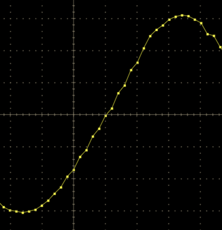 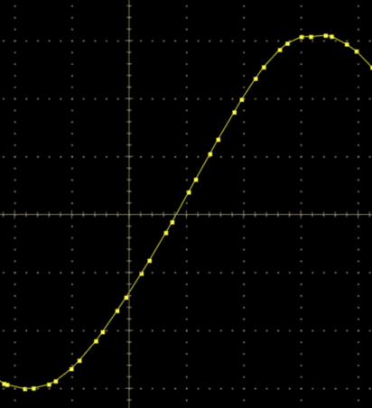
If your points do not lie on a smooth line, you might habe a problem such as the wrong channel for calibration, an offset of 1 in the index of the time array or some other software bug. Measure the same signal with the DRSOsc application and then your code. If the results differ, you have a software problem on your side.
Stefan
|
|
881
|
Tue Mar 15 13:07:50 2022 |
Matias Senger | Time calibration and the C++ API | Thanks for your help. If I look into the app the behavior for the 4 channels is exactly as you show:


Now, when I sample with my code something strange happens, two of the channels are fine and the other two are wrong:

This is a surprise to me because I acquire the 4 channels in the same way within a `for` loop. To get the time data I use `DRSBoard::GetTime` with the `tcalibrated` argument set to `true`. Is there any aditional step to use the calibration?
Best,
Matias.
| Stefan Ritt wrote: |
|
Looks like you have the some time calibration, not sure if it's the correct one. Sample the sine wave from the calibration clock, once with and once without the timing calibration, then you will see if all points lie on a smooth line. Left: without timing calibration, right: with proper timing calibration:
If your points do not lie on a smooth line, you might habe a problem such as the wrong channel for calibration, an offset of 1 in the index of the time array or some other software bug. Measure the same signal with the DRSOsc application and then your code. If the results differ, you have a software problem on your side.
Stefan
|
|
|
651
|
Wed Jan 17 09:51:16 2018 |
Tran Cong Thien | The input signals recorded are different with the signal showed in oscilloscope | Dear Stefan,
I am using an DRS4 board to record the signals from an plastic scintillator detector. It was working really good, yet a few day ago the signals became "not right". When I checked the signal using an oscilloscope it show the normal signals previously recorded. The signal amplitude are clearly reduced (from 0.3 in oscilloscope to lower than 0.1 in DRS4). Can you show me how to show this problem?
Thank you very much!
Best Regards,
Thien |
|
652
|
Wed Jan 17 10:09:09 2018 |
Stefan Ritt | The input signals recorded are different with the signal showed in oscilloscope | First thing is to do another voltage calibration. Disconnect input, "Config", "Execute Voltage Calibration". If this does not fix the problem, the board is probably broken. This can happen if you send very high input singals to the board (like >10V) and exceed the maximul allowed limit from the datasheet. In that case the board needs to be repaired. Please contact me directly (via email) so that we can make you a quote.
Best regards,
Stefan
| Tran Cong Thien wrote: |
|
Dear Stefan,
I am using an DRS4 board to record the signals from an plastic scintillator detector. It was working really good, yet a few day ago the signals became "not right". When I checked the signal using an oscilloscope it show the normal signals previously recorded. The signal amplitude are clearly reduced (from 0.3 in oscilloscope to lower than 0.1 in DRS4). Can you show me how to show this problem?
Thank you very much!
Best Regards,
Thien
|
|
|
340
|
Thu Apr 17 12:02:28 2014 |
Wang | The first channel is wrong. | Hi,
I want to describe this phenomenon again. The diagram below is DRS4 output. There is no input signal. Green is the output8+, blue is the output8-. Output8+ of the first channel is below the baseline. The output is saturation when input ADC. It is not right, and what is it in front of the first channel? It seemed there are two channels. Others channel is suitable. I check the circuit , Hardware is no problem, so I want to konw where the FPGA code is wrong. What reason is caused? Can anyone help me to solve the problem? Thanks! |
| Attachment 1: QQ??20140417174309.jpg
|

|
|
703
|
Tue Jun 19 06:42:23 2018 |
Phan Van Chuan | The data acquisition speed | Dear Stefan,
We are using an DRS4 board V5.1 for building a metering system for the scintillator detector by a Labview program. The program was built based on the functions in DRS.cpp and it reads data from channel 0 very well (Fig 1). Now, I am having a problem with the data acquisition from DRS4 board. The data acquisition speed on this program is only about 30-50 Acq / s, while using the DRS Oscilloscope that of about 300-400 Acq / s.
When the program was installed with fDominoMode = 0 and fDominoActive = 0, the data acquisition speed was about 300-400 Acq / s. However, the waveform is inaccurate.
I do not know if I installed the wrong function! Can you show me how to solve this problem?
In the Labview program, functions (corresponding to functions in DRS.cpp) are called with the following parameters:
InitFPGA();
SetMultiBuffer(0);
fROFS = 1.6; // differential input range -0.5V ... +0.5V
fRange = 0;
SetDAC(fDAC_ROFS_1, fROFS);
fCommonMode = 0.8; // 0.8V +- 0.5V inside NMOS range
SetDAC(fDAC_CALP, fCommonMode);
SetDAC(fDAC_CALN, fCommonMode);
SetDAC(fDAC_BIAS, 0.70);
/* set default number of channels per chip */
SetChannelConfig(0, fNumberOfReadoutChannels - 1, 8);
// set ADC clock phase
fADCClkPhase = 0;
fADCClkInvert = 0;
// default settings
fMultiBuffer = 0;
fNMultiBuffer = 0;
fDominoMode = 1;
fReadoutMode = 1;
fReadPointer = 0;
fTriggerEnable1 = 1;
fTriggerEnable2 = 0;
fTriggerSource = 0;
fTriggerDelay = 0;
fTriggerDelayNs = 0;
fSyncDelay = 0;
fNominalFrequency = 1;
fDominoActive = 1;
// load calibration from EEPROM
ReadCalibration();
...
SetDominoMode(fDominoMode);
SetReadoutMode(fReadoutMode);
EnableTrigger(fTriggerEnable1, fTriggerEnable2);
SetTriggerSource(fTriggerSource);
SetTriggerDelayPercent(0);
SetSyncDelay(fSyncDelay);
SetDominoActive(fDominoActive);
SetFrequency(fNominalFrequency, true);
SetInputRange(fRange);
SelectClockSource(0); // FPGA clock
// disable calibration signals
EnableAcal(0, 0);
SetCalibTiming(0, 0);
EnableTcal(0);
// got to idle state
Reinit();
////////
SetFrequency (1,false);
settranspmode (1);
setinputrange(0);
EnableTcal (0,-,-);
EnableTrigger(1, 0);
SetTriggerSource(0);
SetTriggerLevel(0);
SetTriggerPolarity(false);
SetTriggerDelayNs(512);
// in loop of read data from DRS4:
{
StartDomino();
while (b->IsBusy());
TransferWaves(0, 8);
GetTime(0, 0, b->GetTriggerCell(0), time_array[0]);
GetWave(0, 0, wave_array[0]);
}
Thank you very much!
Best Regards,
Chuan
|
| Attachment 1: wavech0.png
|

|
|