| ID |
Date |
Author |
Subject |
|
661
|
Tue Feb 27 18:04:18 2018 |
Steven Block | DRS4 Dead times | That is extremely helpful! Many thanks. One more question; If I were to take inputs from 2 channels at once, would that scale the dead time to 64us using your example?
Steven
| Stefan Ritt wrote: |
|
XML is very slow to write, and you are probably limited by that. Switch to binary mode, which is much faster. You will see in the end a maximum rate of ~500 Hz, and thus a dead time of 2ms, independent of the sampling speed. Note that you have only an evaluation board, which is optimized for ease of use. If you develop your own electronics, and do optimized readout, you can bring the deadtime down to 30ns x number of samples + 2us, or 32us if you read 1024 values from one channel.
Stefan
| Steven Block wrote: |
|
Hello All,
I am currently trying to figure out how to properly characterize the dead time of the DRS4 board. My most recent experiment to try and answer this question involved using an external trigger that can range from 1Hz to 2MHz. I fed this trigger into the DRS4 and collected 1000 samples with no input to any channels. I repeated this across the range of my external trigger by a factor of ten [10Hz, 100Hz, 1kHz...etc]. After I had saved these runs in XML format, I looked at the difference between timestamps on the events. Attached are my findings. Can someone offer an explanation for the periodic peaks? I am new to the DRS4 and don't really understand how it works. My guess is that there is a buffer that has to be emptied every so often, but if so, the buffer emptying time varies with the frequency of the trigger. I would ideally like to be able to know the relation of the dead time to a particular setting I change on the DRS4 such as locking the sampling speed or changing external trigger frequency.
Best,
Steven
|
|
|
|
663
|
Fri Mar 2 18:08:55 2018 |
Steven Block | ROI | Hello,
I have a question about how ROI works. From what I have read, it will only save data that ocurs some time [ta] dictated by the user after an event is triggered as well as a small time [tb] before the event. The technical manual seems to indicated that the deadtime assciated with operating in ROI mode can be reduced by the following factor:
 . .
Where N is the number of points in the time window (ex. 2048 or 1024). Is it ok to describe this as:

Where N' is the number of samples in the ROI and N is the same as before.
For example, if I were running at 5Gsps (200ps between samples), only recording 1024 samples per event and I had an signal that lasted 2ns, that means the signal would last 10 samples. If I set the ROI to only save 20 samples around this signal, would my Deadtime go to:
 ? (The second portion of this equation comes from a response I recieved earlier, but I just want to make sure I understand this concept properly) ? (The second portion of this equation comes from a response I recieved earlier, but I just want to make sure I understand this concept properly)
I recognize that the caveat is that this would work only if the signal was detected during acquistion, which leads to my next question. If no signals were detected in the 1024*200ps time frame in ROI mode, would the DRS4 go dead for 32us (using the factor = 1 from above equation), or would it dump the earliest events in the buffer for the more recent ones until it detects a signal?
Finally, I assume this functionality can only be utilized with custom electornics with the DRS4, not the evaulation/demo board, please let me know if this is the case.
Best,
Steven |
|
665
|
Fri Mar 2 21:05:48 2018 |
Steven Block | ROI | Great! That is very helpful.
One more question. If no signals were detected in the 1024*200ps time frame in ROI mode, would the DRS4 go dead for 32us (or 30us depending on the supply) for, or would it dump the earliest events in the buffer for the more recent ones until it detects a signal to readout? Or rather, does filling the buffer force a readout or can it dynamically shift out old data until it detects a signal to readout.
Steven
| Stefan Ritt wrote: |
|
N'/N is correct. The 2 us "from the response you got from me" come from the fact that after readout, you have to start the DRS4 again. During this time, the power supply usually becomes slightly unstable, and it takes on the evaluation board about 2us to stabilize it again. Tha't why I add the 2 us. If you don't care about slight offset effect, or if you make a better power supply, you dead time would be 10*30ns = 300ns for 10 samples. Starting the DRS again will take one or two clock cycles from the FPGA, which might add another 30 ns or so, depending on how you program the FPGA. So the best you can achieve for 10 samples is maybe 330 ns, if you have a really good power supply (large capacitors).
You can achieve this functionality with the evaluation board, but you would have to make a special firmware for it.
Stefan
| Steven Block wrote: |
|
Hello,
I have a question about how ROI works. From what I have read, it will only save data that ocurs some time [ta] dictated by the user after an event is triggered as well as a small time [tb] before the event. The technical manual seems to indicated that the deadtime assciated with operating in ROI mode can be reduced by the following factor:
.
Where N is the number of points in the time window (ex. 2048 or 1024). Is it ok to describe this as:
Where N' is the number of samples in the ROI and N is the same as before.
For example, if I were running at 5Gsps (200ps between samples), only recording 1024 samples per event and I had an signal that lasted 2ns, that means the signal would last 10 samples. If I set the ROI to only save 20 samples around this signal, would my Deadtime go to:
? (The second portion of this equation comes from a response I recieved earlier, but I just want to make sure I understand this concept properly)
I recognize that the caveat is that this would work only if the signal was detected during acquistion, which leads to my next question. If no signals were detected in the 1024*200ps time frame in ROI mode, would the DRS4 go dead for 32us (using the factor = 1 from above equation), or would it dump the earliest events in the buffer for the more recent ones until it detects a signal?
Finally, I assume this functionality can only be utilized with custom electornics with the DRS4, not the evaulation/demo board, please let me know if this is the case.
Best,
Steven
|
|
|
|
298
|
Mon Oct 21 14:43:21 2013 |
Stephane Debieux | DRS4 analog outputs - interfacing DRS4 to AD9222 ADC | Hi,
I wish to interface the DRS4 with the 8-channel ADC AD9222 (or AD9637).
I'm reading from the DRS4 datasheet that "the analog output of the DRS4 chip has been designed to match directly the input of the AD9222". OUT+ output of DRS4 is in the range from 0.8V to 1.8V and OUT- output is shifted by the voltage applied to the O-OFS pin.
The span of the AD9222 ADC core is defined by REFT and REFB which are resp. 1.4V and 0.4V in a typical case (AVDD=1.8V, VREF=1V). My understanding is that the ADC analog inputs must be within the voltage range defined by REFT and REFB and so I don't quite see how this matches the DRS4 outputs.
Can we use the full-scale range indeed? Do we have to use AC-coupling with mid-supply bias? What is the point I missed?
Thank you for your help.
|
|
377
|
Tue Oct 7 14:09:02 2014 |
Stephane Debieux | USB Microcontroller firmware | Hi,
I'm trying to recompile the USB microcontroller firmware starting from the drs_eval.c file but I'm not able to get a .iic file close to the one provided with the eval board. It seems to me that this drs_eval.iic file does not match the drs_eval.c and drs_eval.hex files or that I'm doing something wrong. Could you please help or give me an explanation.
Thank you.
Stephane
|
|
379
|
Mon Oct 13 17:08:40 2014 |
Stephane Debieux | USB Microcontroller firmware |
| Stefan Ritt wrote: |
|
| Stephane Debieux wrote: |
|
Hi,
I'm trying to recompile the USB microcontroller firmware starting from the drs_eval.c file but I'm not able to get a .iic file close to the one provided with the eval board. It seems to me that this drs_eval.iic file does not match the drs_eval.c and drs_eval.hex files or that I'm doing something wrong. Could you please help or give me an explanation.
Thank you.
Stephane
|
I did not touch the firmware since a couple of years, but I can confirm that the drs_eval.iic is the correct firmware file, since we use this one on all of our boards. To program it, you need the Cypress USB Console. You remove the jumper (to detach the EEPROM), then power the board (which then boots from the internal memory), connect to the board via the Cypress console, the put back the jumper while the board is running, then program the file into the EEPROM.
Best,
Stefan
|
Thank you Stefan.
Would that be possible to get the corresponding drs_eval.c source file since I'm assuming the one provided with the eval board is not the right one?
Thank you.
Stephane |
|
381
|
Tue Oct 14 16:21:07 2014 |
Stephane Debieux | USB Microcontroller firmware |
| Stefan Ritt wrote: |
|
| Stephane Debieux wrote: |
|
| Stefan Ritt wrote: |
|
| Stephane Debieux wrote: |
|
Hi,
I'm trying to recompile the USB microcontroller firmware starting from the drs_eval.c file but I'm not able to get a .iic file close to the one provided with the eval board. It seems to me that this drs_eval.iic file does not match the drs_eval.c and drs_eval.hex files or that I'm doing something wrong. Could you please help or give me an explanation.
Thank you.
Stephane
|
I did not touch the firmware since a couple of years, but I can confirm that the drs_eval.iic is the correct firmware file, since we use this one on all of our boards. To program it, you need the Cypress USB Console. You remove the jumper (to detach the EEPROM), then power the board (which then boots from the internal memory), connect to the board via the Cypress console, the put back the jumper while the board is running, then program the file into the EEPROM.
Best,
Stefan
|
Thank you Stefan.
Would that be possible to get the corresponding drs_eval.c source file since I'm assuming the one provided with the eval board is not the right one?
Thank you.
Stephane
|
There is only one drs_eval.c version around, and I confirm that it is the one in the distribution. If you use different compiler settings, like optimisations, you might get a different executable file (and thus a .iic file), but the files have the same functionality.
Stefan
|
I'm very sorry to insist but if I take the .hex of the distribution, convert it to .iic using the hex2bix utility, and reprogram the board, I can't read the board correctly (invalid magic number read with drscl for instance). Also, when using the uVision2 project file you provide and compiling the drs_eval.c, I get the same result (i.e. no way to generate a functional .iic file starting from the sources). So, either I'm doing something wrong (and I don't know what) or the drs_eval.c is not the correct one. |
|
383
|
Tue Oct 14 16:34:45 2014 |
Stephane Debieux | USB Microcontroller firmware |
| Stefan Ritt wrote: |
|
| Stephane Debieux wrote: |
|
| Stefan Ritt wrote: |
|
| Stephane Debieux wrote: |
|
| Stefan Ritt wrote: |
|
| Stephane Debieux wrote: |
|
Hi,
I'm trying to recompile the USB microcontroller firmware starting from the drs_eval.c file but I'm not able to get a .iic file close to the one provided with the eval board. It seems to me that this drs_eval.iic file does not match the drs_eval.c and drs_eval.hex files or that I'm doing something wrong. Could you please help or give me an explanation.
Thank you.
Stephane
|
I did not touch the firmware since a couple of years, but I can confirm that the drs_eval.iic is the correct firmware file, since we use this one on all of our boards. To program it, you need the Cypress USB Console. You remove the jumper (to detach the EEPROM), then power the board (which then boots from the internal memory), connect to the board via the Cypress console, the put back the jumper while the board is running, then program the file into the EEPROM.
Best,
Stefan
|
Thank you Stefan.
Would that be possible to get the corresponding drs_eval.c source file since I'm assuming the one provided with the eval board is not the right one?
Thank you.
Stephane
|
There is only one drs_eval.c version around, and I confirm that it is the one in the distribution. If you use different compiler settings, like optimisations, you might get a different executable file (and thus a .iic file), but the files have the same functionality.
Stefan
|
I'm very sorry to insist but if I take the .hex of the distribution, convert it to .iic using the hex2bix utility, and reprogram the board, I can't read the board correctly (invalid magic number read with drscl for instance). Also, when using the uVision2 project file you provide and compiling the drs_eval.c, I get the same result (i.e. no way to generate a functional .iic file starting from the sources). So, either I'm doing something wrong (and I don't know what) or the drs_eval.c is not the correct one.
|
And what happens if you program the .iic file from the distribution?
|
It works as expected. |
|
385
|
Tue Oct 14 16:51:37 2014 |
Stephane Debieux | USB Microcontroller firmware |
| Stefan Ritt wrote: |
|
| Stephane Debieux wrote: |
|
| Stefan Ritt wrote: |
|
| Stephane Debieux wrote: |
|
| Stefan Ritt wrote: |
|
| Stephane Debieux wrote: |
|
| Stefan Ritt wrote: |
|
| Stephane Debieux wrote: |
|
Hi,
I'm trying to recompile the USB microcontroller firmware starting from the drs_eval.c file but I'm not able to get a .iic file close to the one provided with the eval board. It seems to me that this drs_eval.iic file does not match the drs_eval.c and drs_eval.hex files or that I'm doing something wrong. Could you please help or give me an explanation.
Thank you.
Stephane
|
I did not touch the firmware since a couple of years, but I can confirm that the drs_eval.iic is the correct firmware file, since we use this one on all of our boards. To program it, you need the Cypress USB Console. You remove the jumper (to detach the EEPROM), then power the board (which then boots from the internal memory), connect to the board via the Cypress console, the put back the jumper while the board is running, then program the file into the EEPROM.
Best,
Stefan
|
Thank you Stefan.
Would that be possible to get the corresponding drs_eval.c source file since I'm assuming the one provided with the eval board is not the right one?
Thank you.
Stephane
|
There is only one drs_eval.c version around, and I confirm that it is the one in the distribution. If you use different compiler settings, like optimisations, you might get a different executable file (and thus a .iic file), but the files have the same functionality.
Stefan
|
I'm very sorry to insist but if I take the .hex of the distribution, convert it to .iic using the hex2bix utility, and reprogram the board, I can't read the board correctly (invalid magic number read with drscl for instance). Also, when using the uVision2 project file you provide and compiling the drs_eval.c, I get the same result (i.e. no way to generate a functional .iic file starting from the sources). So, either I'm doing something wrong (and I don't know what) or the drs_eval.c is not the correct one.
|
And what happens if you program the .iic file from the distribution?
|
It works as expected.
|
Then why don't you use the .iic file and forget about the hex and c files? Honestly speaking, I don't remember what source file I compiled a couple of years ago, and it could be that an older file slipped into the repository, but that's all I have. I would have to investigate myself, try to compile and program the c file, do the debugging, and find out what the differences are. But unfortunately I don't have time for that right now. So just stick with the .iic file.
|
Thanks for the help.
I'm not doing this for fun, checking that the source matches the .iic ! I know I could directly use the .iic and forget about the hex and c files.
I just wanted to use your source file as the starting point for my own board, as everybody is doing at the application level. |
|
1
|
Mon Dec 15 13:37:38 2008 |
Stefan Ritt | Welcome | Welcome to the DRS4 Discussion Forum. This forum contains information and discussions related to the DRS4 chip. Please subscribe to this forum to receive automatic email updates. If you have any technical questions, please feel free to post it here. |
|
2
|
Wed Jan 14 12:02:04 2009 |
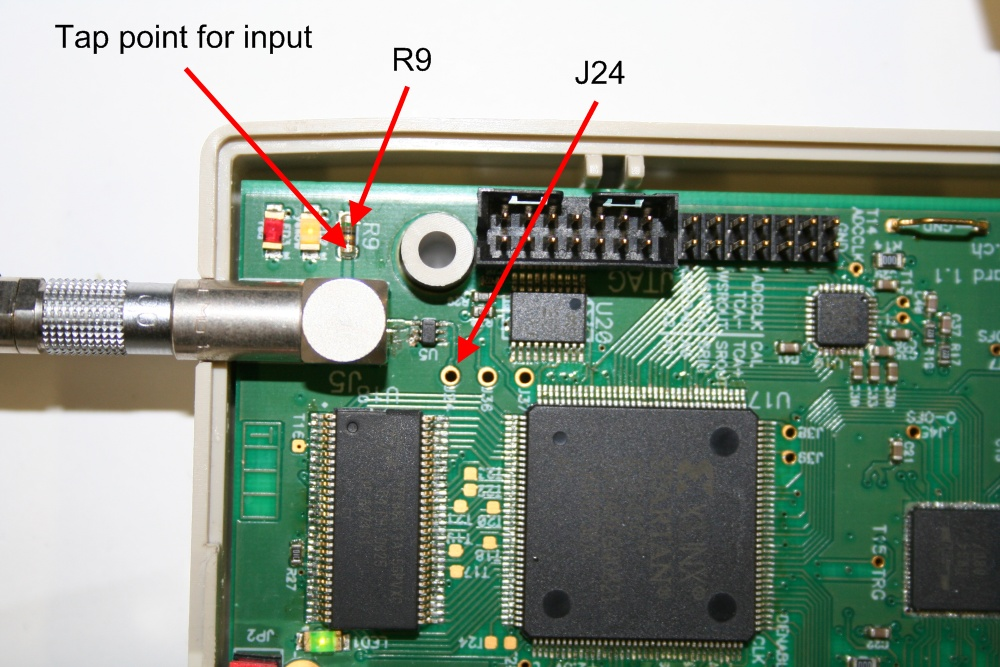
Stefan Ritt | External Trigger Input requirements | Several people mentioned that the external trigger input (TTL) does not work on the DRS4 Evaluation Board Rev. 1.1. This is not true. The requirement however is that the input signal must exceed approximately 1.8V. Since the input is terminated with 50 Ohms, not all TTL drivers may deliver enough current to exceed this threshold. To verify this, the trigger signal can be monitored with an oscilloscope at test point J24. Only if the input signal exceeds 1.8V, the signal will be seen at J24 and correctly trigger the FPGA. If the TTL driver is too weak, the termination resistor R9 can be optionally removed, but care should then be taken that reflections in the trigger input do not cause double triggers. The locations of the tap point for the input signal, the termination resistor R9 and the tap point J24 after the input level converter U5 are shown in this image:
|
|
3
|
Wed Jan 14 13:41:44 2009 |
Stefan Ritt | External Trigger Input requirements |
Another tricky issue comes from the fact that the external TTL trigger and the comparator are in a logical OR. So if the comparator level is set such that the signal is always over the threshold, the trigger is always "on" and the TTL trigger does not have any effect. It is therefore necessary to set the analog trigger level to a very high value in order to make the TTL trigger work. |
|
4
|
Wed Feb 11 12:21:07 2009 |
Stefan Ritt | Corrected datasheet Rev. 0.8 | Please note the new datasheet Rev. 0.8 available from the DRS web site. It fixes the label of pin #76, which was AGND but is actualy AVDD. The input IN8+ is located at pin #20 and not at pin #19 as described in the old table 2. |
|
5
|
Mon Feb 23 09:24:24 2009 |
Stefan Ritt | Rise-time measurements | Many applications using the DRS4 need to measure fast rising signals, like for PMTs or MCPs. This short note shows the minimal rise-times which can be measured with different input signal conditioning.
Evaluation Board
The evaluation board contains four passive transformers ADT1-1WT from Mini-Circuits to convert the single-ended input signal into a differential signal. Although these parts are rated 800 MHz bandwidth (-3dB), they have hard time to drive the DRS4 inputs. This is because at high frequencies the input impedance of DRS4 becomes pretty small (~20 Ohm at 500 MHz) due to its capacitive nature. Furthermore, each transformer drives two DRS4 inputs (channel cascading) which enhances this problem by a factor of two. We made a quick test sending a signal to the evaluation board with a rise time of 277ps and a fall time of 280ps. The result measured with the evaluation board is seen here:
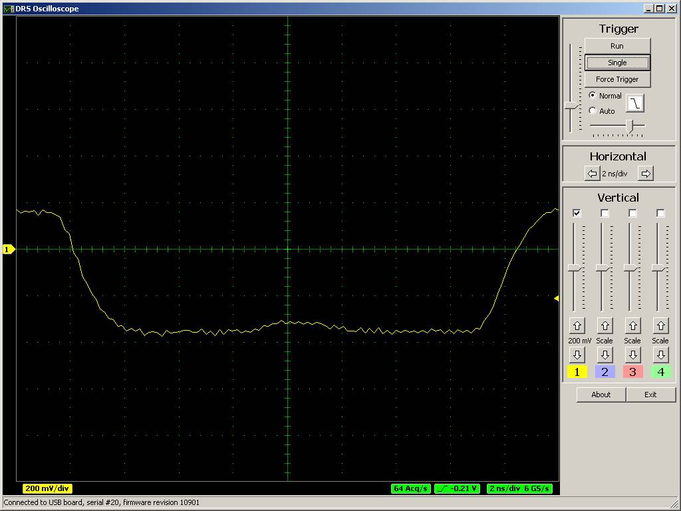
The measured rise-time (10%-90%) is only about 2ns. Disconnecting the second channel from each transformer improves this situation a bit:
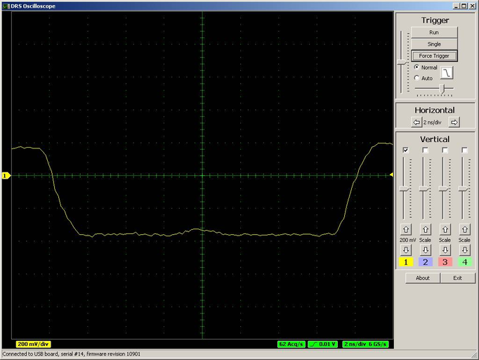
so the rise-time comes down to ~1.6ns.
Active ADA4937 driver
We tested the behavior using an active buffer ADA4937 to replace the passive transformer. Without the DRS4 connected to this buffer, we measured with the oscilloscope a rise time of 408ps and a fall time of 644ps. When we connect the DRS4 (single channel), this values increase to 702ps (rise) and 1400ps (fall), all measured with a differential oscilloscope probe (WL300 4 GHz Bandwidth, LeCroy 7300A, 3 GHz Bandwidth). In this case the rise time seen by the DRS4 is wieth ~700ps accordingly shorter:

(The signal was not properly terminated and therefore we have a small overswing).
Conclusion
To obtain an optimal rise-time measurement, the design of the input stage is rather important. A fast active driver seems to do a better job than a passive transformer (which was used on the evaluation board for power reasons). Connecting only one DRS4 channel to the input improves the rise-time measurement significantly. If channel cascading is still needed, a design should use one driver for each channel, and not driver two or more DRS4 inputs from a single buffer.
If anybody comes up with an even better input driver, I'm happy to publish the results here. |
|
6
|
Mon Apr 27 15:09:49 2009 |
Stefan Ritt | Amplitude and Timing calibration for DRS4 Evaluation Board | This is a quick notification to all users of the current DRS4 evaluation board.
As you all know, the DRS4 chip needs some calibration for each individual cell which corrects the offset and the non-equidistant width in time. While the first evaluation boards have been shipped without this calibration, the current version of the software implements a full amplitude and timing calibration. The offset correction reduces the noise of the board by almost an order of magnitude to below 1 mV RMS. The timing calibration using an on-board reference clock allows a timing accuracy in the order of 10 ps. To illustrate that the following two pictures show a reference clock signal before and after timing calibration:
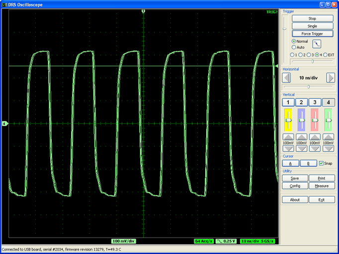
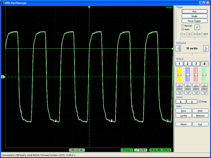
The integral temporal nonlineairy at 5 GSPS before timing calibration is about 600 ps as can be seen by the jitter of the overlaid waveforms.
In order to do a timing calibration, the firmware revison 13297 or later is required. The current software package 2.1 contains an updated firmware, but unfortunately one needs a Xilinx download cable to flash this new firmware (see http://drs.web.psi.ch/download/ under "Software Versions"). If some people want an update but do not want to buy such a cable, we offer a free update at our institute (just the postage has to be paid). The old evaluation board (Rev. 1.0, plastic housing) can unfortunately not be updated.
After the offset calibration is made, there are small (~20mV) short spikes left. They probably come from some cross-talk between the USB interface and the analog part of the board. This is currently under investigation. If new updates become available, they will be announced in this forum.
April 27th, 2009,
Stefan Ritt |
|
7
|
Tue Apr 28 11:44:07 2009 |
Stefan Ritt | Simple example application to read a DRS evaluation board | Several people asked for s simple application to guide them in writing their own application to read out a DRS board. Such an application has been added in software revions 2.1.1 and is attached to this message. This example program drs_exam.cpp written in C++ does the following necessary steps to access a DRS board:
- Crate a "DRS" object and scan all USB devices
- Display found DRS boards
- Initialize the first found board and set the sampling frequency to 5 GSPS
- Enable internal trigger on channel #1 with 250 mV threshold
- Start acquisition and wait for a trigger
- Read two waveforms (both time and amplitude)
- Repeat this 10 times
I know that we are still missing a good documentation for the DRS API, but I have not yet found the time to do that. I hope the example program is enough for most people to start writing own programs. For Windows users (MS Visual C++ 8.0) there is a drs.sln project file, and for linux users there is a Makefile which can be used to compile this example program.
|
|
8
|
Wed Apr 29 07:57:33 2009 |
Stefan Ritt | Simple example application to read a DRS evaluation board |
| Stefan Ritt wrote: |
|
Several people asked for s simple application to guide them in writing their own application to read out a DRS board. Such an application has been added in software revions 2.1.1 and is attached to this message. This example program drs_exam.cpp written in C++ does the following necessary steps to access a DRS board:
- Crate a "DRS" object and scan all USB devices
- Display found DRS boards
- Initialize the first found board and set the sampling frequency to 5 GSPS
- Enable internal trigger on channel #1 with 250 mV threshold
- Start acquisition and wait for a trigger
- Read two waveforms (both time and amplitude)
- Repeat this 10 times
I know that we are still missing a good documentation for the DRS API, but I have not yet found the time to do that. I hope the example program is enough for most people to start writing own programs. For Windows users (MS Visual C++ 8.0) there is a drs.sln project file, and for linux users there is a Makefile which can be used to compile this example program.
|
One note: The program drs_exam.cpp published in the previous message needs the current version of the DRS library in DRS.cpp and DRS.h. They are contained in the software release 2.1.1 which has to be downloaded. For simplicity, I attached the two files to this message. |
|
9
|
Wed Jun 10 12:46:43 2009 |
Stefan Ritt | Input range switch added in Version 2.1.3 | A new software verison for the DRS4 Evaluation Board has been has been released. Version 2.1.3 adds a switch for the input range of the DRS4 board. Once can choose between -0.5V...0.5V and 0V...1V:
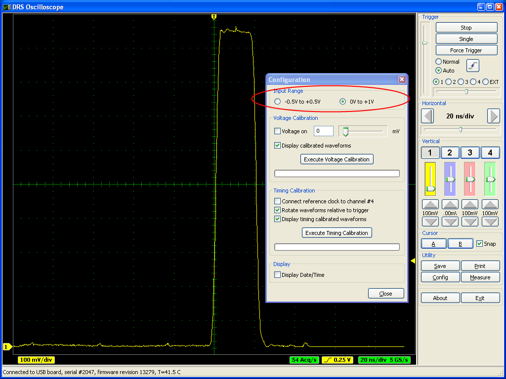
A board firmware update is not necessary for this. It was originally planned to have even a negative range -1V...0V, but this is not possible with the current board design. People who want to record negative pulses have to use an inverter to produce positive pulses. In a future version of the board it might be possible to include this functionality since this is determined by the analog front-end and not the DRS4 chip. |
|
10
|
Tue Jul 7 16:39:57 2009 |
Stefan Ritt | Power up problem and remedy | Maybe some of you have experienced that the DRS4 chip can get pretty hot after power up. After it's initialized the first time, the power consumption goes back to normal. I finally found the cause of this problem and have a remedy. Here is the new paragraph from the updated data sheet:
During power-up, care has to be taken that the DENABLE and DWRITE signals are low. If not, the domino wave can get started before the power supply voltages are stable, which brings the DRS4 chip into a state where it draws a considerable amount of current and heats up significantly. This can be problematic if the signals are directly generated by a FPGA, since most FPGAs have internal pull-up resistors which get activated during the configuration phase of the FPGA. In such a case, the DENABLE and DWRITE signals should be connected to GND with a pull down resistor. This resistor should be much smaller than the FPGA pull-up resistor in order to keep the signals close to GND during the FPGA configuration. A typical value is 4.7 kOhm.
The attached schematics shows the location of the two required resistors. |
|
11
|
Thu Jul 9 09:11:03 2009 |
Stefan Ritt | Current problems with drs_exam.cpp | The current version of the DRS readout example program drs_exam.cpp has two problems:
- The sampling frequency cannot be changed, it will always stay in the region around 5 GSPS
- The waveform obtained by GetWave is rotated such that the first DRS cell corresponds to the first array bin
Both problems have been fixed and the fix will be contained in an upcoming software release. |
|