| ID |
Date |
Author |
Subject |
|
480
|
Mon Feb 29 13:09:29 2016 |
Stefan Ritt | baseline shift | The baseline shift comes from some instable power supply inside the evaluation board which cannot be controlled to the mV level. In a real measurement, you usually get an additional baseline shift due to some environmental electromagnetic interferences, such as a 50 Hz signal. People fix this shifting baseline by always aquiring a small portion (10-20 samples) of the baseline before any signal from a particle detector. The signal is then corrected event-by-event by subtracting the baseline from each waveform. By doing that, you fix not only the 50 Hz noise, but also the shifting baseline you mention.
Stefan
| Dmitry Philippov wrote: |
|
Hello! My name is Dmitry. I am from SiPM Lab is NRNU MEPhI (Russia, Moscow). We bought DRS4 evaluation board V5 with firmware 21305. We use 5.0.4 build 21911 2015-11-23 software version (and before that we used 5.0.3 build 21508, 2014-10-15) with Windows 7 32bit.
We observe some strange behaviour. When we save waveforms (in xml or binary data) we see that some of them have the baseline shifted of about -5 mV.
The first picture (pic1) is 1000 waveforms which were glued in one. It is clearly see that baseline quite often has the shift.
The same effect can be seen without saving (writting): rarely when we use normal or auto trigger mode (pic3), and always in single trigger mode (pic2).
The images are attached.
Do you have any idea how it can be fixed?
Thanks, Dmitry.
|
|
|
479
|
Mon Feb 29 12:58:17 2016 |
Dmitry Philippov | baseline shift | Hello! My name is Dmitry. I am from SiPM Lab is NRNU MEPhI (Russia, Moscow). We bought DRS4 evaluation board V5 with firmware 21305. We use 5.0.4 build 21911 2015-11-23 software version (and before that we used 5.0.3 build 21508, 2014-10-15) with Windows 7 32bit.
We observe some strange behaviour. When we save waveforms (in xml or binary data) we see that some of them have the baseline shifted of about -5 mV.
The first picture (pic1) is 1000 waveforms which were glued in one. It is clearly see that baseline quite often has the shift.
The same effect can be seen without saving (writting): rarely when we use normal or auto trigger mode (pic3), and always in single trigger mode (pic2).
The images are attached.
Do you have any idea how it can be fixed?
Thanks, Dmitry.
|
| Attachment 1: pic1.png
|

|
| Attachment 2: pic2.png
|

|
| Attachment 3: pic3.png
|

|
|
478
|
Tue Feb 16 11:55:54 2016 |
Martin Petriska | Saving histogram data |
| Robert Adams wrote: |
|
I would really love to be able to save histogram data, though I have not been able to do this. I could take a screenshot and extract the data from an image, but would prefer to avoid this if there is a simpler way... possibly I have overlooked something obvious? Thanks very much for any advice or tips.
|
You can use qtpals, there is posibility to save histograms (energy, time diference), only set trigger on channel which you use. https://sourceforge.net/projects/qtpals/files/?source=navbar |
|
477
|
Tue Feb 16 11:21:43 2016 |
Stefan Ritt | Saving histogram data | There is no histogram save functoinality in ther DRSOscilloscope program - on purpose. The board and the software are meant to evaluate the board, not to replace a full DAQ system. If we want to save histograms, you maybe also want to set the range, make cuts, do fits etc. So it would take lots of resources to add all that. Therefore we recommend to use the stand-alone C program drs_exam.cpp to read the board, the you can either do whatever you want in the C program, including saving of histograms. Alternatively, you can use ROOT to analyze binary stored DRS data and do whatever histogram manipulation you want there.
Stefan
| Robert Adams wrote: |
|
I would really love to be able to save histogram data, though I have not been able to do this. I could take a screenshot and extract the data from an image, but would prefer to avoid this if there is a simpler way... possibly I have overlooked something obvious? Thanks very much for any advice or tips.
|
|
|
476
|
Fri Jan 15 08:09:00 2016 |
Stefan Ritt | Triggering of DRS4 in the fastest sampling mode | Hi Chris,
if you ever used an oscilloscope, you might be familar with the button controlling the riger in respect to "risign edge" vs. "falling edge". I copied the same for the DRS software. So just click on that button:
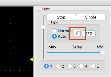
and you will get what you want. Also the AND/OR gets reversed this way. If you select rising edge (default), the AND will be made if both signals are ABOVE the threshold, that's why it does not work for you. If you select falling edge, the AND will be made if both signals are BELOW the threshold. For negative pulses you need falling edge.
Stefan
| Chris Thompson wrote: |
|
I am attempting to use the DRS4 to measure the timing resolution of a pair of SensL silicon photomultipliers (SiPM). In order to do this I need to trigger the DRS4 only when there is a coincidence between the two input signals, and hopefully make histograms of the relative detection times of each detector.
There are two completely separate issues. (1) I think this may just be a labelling error. In the first image (OR_mode_selected) one can clearly see two pulses which are very similar. In this mode, both signals are present, and are always present. I think this should be the "AND", not "OR" of the two signals. Contrast this with the second image where I have selected "AND_mode". Clearly only one signal is present, and either signal trigges an event, so this should be "OR", not "AND"
The second issue is, for me, much more serious. I want to sample the leading edge of this event in order to determine its "time". The little "T" at the top of each image is, I believe the "trigger point" in the first two images. However, this is well after the part of the signal I am interested in. The first two images were at 2 GigaSamples/sec. The third is at 5 GigaSamples/sec. Clearly the event I am interested in processing is over by then. At the lower sampling rate, I can see well before the "T", but at the higher one I can only see after the "T". I had built an external "coincidence circuit" and the "external trigger mode" hoping to to circumvent this issue by using very long cables to delay the signals inut to the DRS4, But even then I have not been successful in getting the to work.
I am using version 5.0.3 on a PC as the version released after that did not work.
I hope some can help!
Chris Thompson
|
|
|
475
|
Thu Jan 14 21:49:37 2016 |
Chris Thompson | Triggering of DRS4 in the fastest sampling mode | I am attempting to use the DRS4 to measure the timing resolution of a pair of SensL silicon photomultipliers (SiPM). In order to do this I need to trigger the DRS4 only when there is a coincidence between the two input signals, and hopefully make histograms of the relative detection times of each detector.
There are two completely separate issues. (1) I think this may just be a labelling error. In the first image (OR_mode_selected) one can clearly see two pulses which are very similar. In this mode, both signals are present, and are always present. I think this should be the "AND", not "OR" of the two signals. Contrast this with the second image where I have selected "AND_mode". Clearly only one signal is present, and either signal trigges an event, so this should be "OR", not "AND"
The second issue is, for me, much more serious. I want to sample the leading edge of this event in order to determine its "time". The little "T" at the top of each image is, I believe the "trigger point" in the first two images. However, this is well after the part of the signal I am interested in. The first two images were at 2 GigaSamples/sec. The third is at 5 GigaSamples/sec. Clearly the event I am interested in processing is over by then. At the lower sampling rate, I can see well before the "T", but at the higher one I can only see after the "T". I had built an external "coincidence circuit" and the "external trigger mode" hoping to to circumvent this issue by using very long cables to delay the signals inut to the DRS4, But even then I have not been successful in getting the to work.
I am using version 5.0.3 on a PC as the version released after that did not work.
I hope some can help!
Chris Thompson |
| Attachment 1: OR_mode_selected.jpg
|

|
| Attachment 2: AND_mode_selected.jpg
|

|
| Attachment 3: 20ns_per_div.jpg
|

|
|
474
|
Thu Jan 14 14:11:06 2016 |
Stefan Ritt | Dtap stops toggling after 40msec | Thanks for the update, I will add a note into the data sheet.
| mony orbach wrote: |
|
surrey i forgot to update..
after carefully examining our VHDL we found out that there are brief times that we put A0-A3 in 1111
after making shore that a0-a3 never get 1111 value thae drs4 woks as expected.
The dtap toggols ok.
We can sample and read all the data channels.
So, putting A0-A3 value of 1111 even for very short period " confuse " the DRS and then it start to behave in a strange manner.
mony
| Stefan Ritt wrote: |
|
While I can understand 1., I'm puzzeled by 2.
If you put the chip in standby mode, the internal current sources are switched off, which of course make the domino wave non-functional. This is clearly stated in the data sheet.
Concerning the DMODE bit, we operate all (!) our chips with DMODE=1. Actually this is the default value. After a reset, all register bits are "1", which enables the PLL and causes DTAP to oscillate. If DMODE=1, the DTAP signal should toggle only once (!) since the domino loop is not closed. So the scope traces you showed previously are consistent with the standby mode, but not possible with ANY setting of DMODE.
Stefan
| mony orbach wrote: |
|
Hi
We have resolve the problem, the Dtap is now working correctly.
There were two problems:
- After configuration we put the all address bits to one (standby mode)
We are now setting the address bits to all zero. Failure
to do so result in Dtap stop toggling after several hundred milliseconds.
- The DMODE bit in contradiction to the data sheet should be set to 0
And not to 1.
Is this a known bug in the chip?
Only bay setting DMODE to zero we got the Dtap to work correctly.
The PLL locks after 1 milisec.
If we set it to one we get Dtap that stop toggling after several hundred milliseconds.
We have test it on two boards, they both worked in the same.
Never did we get a One shot Dtap.
Did you published a errata page to the drs4?
Thanks, Mony
|
|
|
|
|
473
|
Thu Jan 14 14:00:26 2016 |
mony orbach | Dtap stops toggling after 40msec | surrey i forgot to update..
after carefully examining our VHDL we found out that there are brief times that we put A0-A3 in 1111
after making shore that a0-a3 never get 1111 value thae drs4 woks as expected.
The dtap toggols ok.
We can sample and read all the data channels.
So, putting A0-A3 value of 1111 even for very short period " confuse " the DRS and then it start to behave in a strange manner.
mony
| Stefan Ritt wrote: |
|
While I can understand 1., I'm puzzeled by 2.
If you put the chip in standby mode, the internal current sources are switched off, which of course make the domino wave non-functional. This is clearly stated in the data sheet.
Concerning the DMODE bit, we operate all (!) our chips with DMODE=1. Actually this is the default value. After a reset, all register bits are "1", which enables the PLL and causes DTAP to oscillate. If DMODE=1, the DTAP signal should toggle only once (!) since the domino loop is not closed. So the scope traces you showed previously are consistent with the standby mode, but not possible with ANY setting of DMODE.
Stefan
| mony orbach wrote: |
|
Hi
We have resolve the problem, the Dtap is now working correctly.
There were two problems:
- After configuration we put the all address bits to one (standby mode)
We are now setting the address bits to all zero. Failure
to do so result in Dtap stop toggling after several hundred milliseconds.
- The DMODE bit in contradiction to the data sheet should be set to 0
And not to 1.
Is this a known bug in the chip?
Only bay setting DMODE to zero we got the Dtap to work correctly.
The PLL locks after 1 milisec.
If we set it to one we get Dtap that stop toggling after several hundred milliseconds.
We have test it on two boards, they both worked in the same.
Never did we get a One shot Dtap.
Did you published a errata page to the drs4?
Thanks, Mony
|
|
|
|
472
|
Tue Jan 12 21:02:31 2016 |
Stefan Ritt | Compiling DRS-exam | I guess you are compiling under MS Windows ??? You probably don't link correctly to the USB lib. Try to compile the examples coming with libusb-1.0 to make you everything is right there.
| Jack Bargemann wrote: |
|
I am trying to compile drs-exam, but am getting an error message I do not understand:
1>musbstd.obj : error LNK2019: unresolved external symbol _usb_open referenced in function _musb_open
1>musbstd.obj : error LNK2019: unresolved external symbol _usb_close referenced in function _musb_close
1>musbstd.obj : error LNK2019: unresolved external symbol _usb_get_descriptor referenced in function _musb_get_device
1>musbstd.obj : error LNK2019: unresolved external symbol _usb_bulk_write referenced in function _musb_write
1>musbstd.obj : error LNK2019: unresolved external symbol _usb_bulk_read referenced in function _musb_read
1>musbstd.obj : error LNK2019: unresolved external symbol _usb_set_configuration referenced in function _musb_open
1>musbstd.obj : error LNK2019: unresolved external symbol _usb_claim_interface referenced in function _musb_open
1>musbstd.obj : error LNK2019: unresolved external symbol _usb_release_interface referenced in function _musb_close
1>musbstd.obj : error LNK2019: unresolved external symbol _usb_set_altinterface referenced in function _musb_set_altinterface
1>musbstd.obj : error LNK2019: unresolved external symbol _usb_reset referenced in function _musb_reset
1>musbstd.obj : error LNK2019: unresolved external symbol _usb_init referenced in function _musb_open
1>musbstd.obj : error LNK2019: unresolved external symbol _usb_set_debug referenced in function _musb_open
1>musbstd.obj : error LNK2019: unresolved external symbol _usb_find_busses referenced in function _musb_open
1>musbstd.obj : error LNK2019: unresolved external symbol _usb_find_devices referenced in function _musb_open
1>musbstd.obj : error LNK2019: unresolved external symbol _usb_get_busses referenced in function _musb_open
I have tried redownloading a different version of libusb-1.0, but the problem was not solved. What might I be doing wrong?
|
|
|
471
|
Tue Jan 12 17:57:03 2016 |
Jack Bargemann | Compiling DRS-exam | I am trying to compile drs-exam, but am getting an error message I do not understand:
1>musbstd.obj : error LNK2019: unresolved external symbol _usb_open referenced in function _musb_open
1>musbstd.obj : error LNK2019: unresolved external symbol _usb_close referenced in function _musb_close
1>musbstd.obj : error LNK2019: unresolved external symbol _usb_get_descriptor referenced in function _musb_get_device
1>musbstd.obj : error LNK2019: unresolved external symbol _usb_bulk_write referenced in function _musb_write
1>musbstd.obj : error LNK2019: unresolved external symbol _usb_bulk_read referenced in function _musb_read
1>musbstd.obj : error LNK2019: unresolved external symbol _usb_set_configuration referenced in function _musb_open
1>musbstd.obj : error LNK2019: unresolved external symbol _usb_claim_interface referenced in function _musb_open
1>musbstd.obj : error LNK2019: unresolved external symbol _usb_release_interface referenced in function _musb_close
1>musbstd.obj : error LNK2019: unresolved external symbol _usb_set_altinterface referenced in function _musb_set_altinterface
1>musbstd.obj : error LNK2019: unresolved external symbol _usb_reset referenced in function _musb_reset
1>musbstd.obj : error LNK2019: unresolved external symbol _usb_init referenced in function _musb_open
1>musbstd.obj : error LNK2019: unresolved external symbol _usb_set_debug referenced in function _musb_open
1>musbstd.obj : error LNK2019: unresolved external symbol _usb_find_busses referenced in function _musb_open
1>musbstd.obj : error LNK2019: unresolved external symbol _usb_find_devices referenced in function _musb_open
1>musbstd.obj : error LNK2019: unresolved external symbol _usb_get_busses referenced in function _musb_open
I have tried redownloading a different version of libusb-1.0, but the problem was not solved. What might I be doing wrong? |
|
470
|
Tue Jan 12 16:06:07 2016 |
Stefan Ritt | Use of Channel Cascading in drs_exam.cpp | Hi Larry,
sorry my late reply, swamped with work here. You were right in the modifictions you did, congrats. The speed limitation of 500 events come from USB2, which simply is not fast enough. The 500 Hz are mentioned on the evaluation board web site, so you should have seen that before ordering. Some people build their own hardware around the chip, in which case they get higher rates. The "hard" limit is the DRS4 readout speed, which is 30ns per sample. So if you have 8 ADCs in parallel, and you only need 100 samples of your waveform, the readout time is 3 us, in which case you could go up to a few 10 kHz without much of a dead time.
Cheers,
Stefan
| Larry Byars wrote: |
|
An update. I have been successful in making modifications to drs_exam.cpp so that I can get 2048 samples per channel.. The main changes were to the size of the time_array and wave_array and adding a call to Set ChannelConfig(0,8,4). It was also necessary to change the parameters to GetWave so that the Trigger Cell and WSR values were passed to get the channel combinations correct (2048 channel.ppt).
I've moved on to try to increase the speed of acquisition (I get only about 500 events/sec) and trying to understand the corrections.Working through the source code slowly...
Regards,
Larry Byars
| Larry Byars wrote: |
|
Hello Stefan,
Here in Rockford, TN we just got a new DRS4 evaluation board (Serail # 2612, Board Type 9, Firmware 21305) which is labeled as combined 2048.
It looks like the drs_exam.cpp only works with 1024 samples per channel. We'd like to be able to get 2048 samples from each of the four channels but I am uncertain what code modifications are necessary support this.
Could you offer a suggestion? I've searched the forum for cascade and read several threads but they are pretty old. One even says it isn't supported in the evaluation board, but I think that is no longer the case.
Thanks for your help,
Larry Byars
|
|
|
|
469
|
Tue Jan 12 15:42:31 2016 |
Larry Byars | Use of Channel Cascading in drs_exam.cpp | An update. I have been successful in making modifications to drs_exam.cpp so that I can get 2048 samples per channel.. The main changes were to the size of the time_array and wave_array and adding a call to Set ChannelConfig(0,8,4). It was also necessary to change the parameters to GetWave so that the Trigger Cell and WSR values were passed to get the channel combinations correct (2048 channel.ppt).
I've moved on to try to increase the speed of acquisition (I get only about 500 events/sec) and trying to understand the corrections.Working through the source code slowly...
Regards,
Larry Byars
| Larry Byars wrote: |
|
Hello Stefan,
Here in Rockford, TN we just got a new DRS4 evaluation board (Serail # 2612, Board Type 9, Firmware 21305) which is labeled as combined 2048.
It looks like the drs_exam.cpp only works with 1024 samples per channel. We'd like to be able to get 2048 samples from each of the four channels but I am uncertain what code modifications are necessary support this.
Could you offer a suggestion? I've searched the forum for cascade and read several threads but they are pretty old. One even says it isn't supported in the evaluation board, but I think that is no longer the case.
Thanks for your help,
Larry Byars
|
|
|
468
|
Tue Jan 12 12:57:46 2016 |
Stefan Ritt | PC software beyond Windows 7 | The 5.0.4 version was corrupt on our server. I fixed it, so now it shoudl also work fine (although there are only very minor changes between 5.0.3 and 5.0.4).
/Stefan
| Chris Thompson wrote: |
|
On a hunch, I tried downloading V 5.0.3 instead. This works, and I now have the oscilloscope mode displaying signals! (just to make sure, I re-tire version 5.0.4 and still get the same error. So, in summary V 5.0.3 seems to install successfully and work with Windows 10, but the newer V5.0.4 does not install... I assmume that I am missing something though, as the newer version is 10 Mbytes bigger!
| Chris Thompson wrote: |
|
I tried restarting Windows 10 in a way the allowed me to use "advanced startup options" Option 7 suggested it was to restart without mandatory driver signing. However, the error persists. Has anyone tested this latest version 5.0.4 on Windows 10? My hardware arrived today, and I am anxious to test it.!!!!
| Chris Thompson wrote: |
|
I tried this suggestion of changing the startup settings to ingore driver license signing (as suggested in the post # 434), but when I tried to install the software I got a error message which I captured from the screen and I have attached. Perhaps I have the wrong version, or, as suggested, the file I downloaded from your site is incomplete?
| Stefan Ritt wrote: |
|
Have a look here elog:434
| Chris Thompson wrote: |
|
I am new to this forum. I have ordered a DRS4 evaluation board for doing experiments with very fast PET detectors. It has not arrived yet. The version of the manual I downloaded today shows software installation instructions for Windows 7 and earlier versions. I intend to use it on a 64bit PC running Windows 8.1. Will the Windows 7 driver work, or is there an updated version for Windows 8 or 10?
|
|
|
|
|
|
|
467
|
Wed Jan 6 15:51:58 2016 |
Larry Byars | Use of Channel Cascading in drs_exam.cpp | Hello Stefan,
Here in Rockford, TN we just got a new DRS4 evaluation board (Serail # 2612, Board Type 9, Firmware 21305) which is labeled as combined 2048.
It looks like the drs_exam.cpp only works with 1024 samples per channel. We'd like to be able to get 2048 samples from each of the four channels but I am uncertain what code modifications are necessary support this.
Could you offer a suggestion? I've searched the forum for cascade and read several threads but they are pretty old. One even says it isn't supported in the evaluation board, but I think that is no longer the case.
Thanks for your help,
Larry Byars
|
|
466
|
Wed Dec 30 17:00:00 2015 |
Stefan Ritt | Dtap stops toggling after 40msec | While I can understand 1., I'm puzzeled by 2.
If you put the chip in standby mode, the internal current sources are switched off, which of course make the domino wave non-functional. This is clearly stated in the data sheet.
Concerning the DMODE bit, we operate all (!) our chips with DMODE=1. Actually this is the default value. After a reset, all register bits are "1", which enables the PLL and causes DTAP to oscillate. If DMODE=1, the DTAP signal should toggle only once (!) since the domino loop is not closed. So the scope traces you showed previously are consistent with the standby mode, but not possible with ANY setting of DMODE.
Stefan
| mony orbach wrote: |
|
Hi
We have resolve the problem, the Dtap is now working correctly.
There were two problems:
- After configuration we put the all address bits to one (standby mode)
We are now setting the address bits to all zero. Failure
to do so result in Dtap stop toggling after several hundred milliseconds.
- The DMODE bit in contradiction to the data sheet should be set to 0
And not to 1.
Is this a known bug in the chip?
Only bay setting DMODE to zero we got the Dtap to work correctly.
The PLL locks after 1 milisec.
If we set it to one we get Dtap that stop toggling after several hundred milliseconds.
We have test it on two boards, they both worked in the same.
Never did we get a One shot Dtap.
Did you published a errata page to the drs4?
Thanks, Mony
|
|
|
465
|
Wed Dec 30 16:25:35 2015 |
mony orbach | Dtap stops toggling after 40msec | Hi
We have resolve the problem, the Dtap is now working correctly.
There were two problems:
- After configuration we put the all address bits to one (standby mode)
We are now setting the address bits to all zero. Failure
to do so result in Dtap stop toggling after several hundred milliseconds.
- The DMODE bit in contradiction to the data sheet should be set to 0
And not to 1.
Is this a known bug in the chip?
Only bay setting DMODE to zero we got the Dtap to work correctly.
The PLL locks after 1 milisec.
If we set it to one we get Dtap that stop toggling after several hundred milliseconds.
We have test it on two boards, they both worked in the same.
Never did we get a One shot Dtap.
Did you published a errata page to the drs4?
Thanks, Mony
| mony orbach wrote: |
|
Hi Stefan
Thanks for your input.
We are in the process of assemble another PCB board.
so soon we can compere between two boards.
As for the PLLEN bit, we set it.
We checked several times the soldering of the DRS4 using a microscope.
Everything looks ok.
In what method do you recommend to solder the DRS4?
Thanks for the invitation to meet.
120Km is not so far J
mony
| Stefan Ritt wrote: |
|
Thanks for posting the plots. It really looks like the PLL is not working. I see two possible reasons: 1) The PLLEN bit in the configuration register is not set and 2) The REFCLK signal does not reach the chip. We had cases whrere people had a hard time to solder the DRS4 correctly due to the small pins. So if the REFCLK+ and REFCLK- signals have a poor connection, then the PLL of course won't work. Putting some more tin at the pins manually usually helps. Or remove the chip completely and try with another chip. In theory there is the possibility that the internal bond wire of the REFCLK signal has a bad connection, but we tested all chips we send out so we should have seen that. But trying with another chip cannot hurt in general. Next month I'm coming to the Weizman Institute for the ISOTDAQ shool. If you want we can meet there if you don't mind the 120 km drive from Haifa.
Stefan
| mony orbach wrote: |
|
Hi
We have some measures to show (attached)
- Dtap and Denable
- Dtap+Denable in zoom
- Dtap + Refck+
- Dtap + Dspeed
From the screen shots it can be seen that refck+ is not synchronized with Dtap (PLL not working correctly)
And Dspeed is going done to zero after some time.
In our system Dspeed is shorted to pllout.
So it looks like pllout do not pump the RC filter capacitors.
We tested various value of R and C's.
Also we checked that pllout is sorted to Dspeed.
Thanks, mony
|
|
|
|
|
464
|
Mon Dec 28 11:21:54 2015 |
mony orbach | Dtap stops toggling after 40msec | Hi Stefan
Thanks for your input.
We are in the process of assemble another PCB board.
so soon we can compere between two boards.
As for the PLLEN bit, we set it.
We checked several times the soldering of the DRS4 using a microscope.
Everything looks ok.
In what method do you recommend to solder the DRS4?
Thanks for the invitation to meet.
120Km is not so far J
mony
| Stefan Ritt wrote: |
|
Thanks for posting the plots. It really looks like the PLL is not working. I see two possible reasons: 1) The PLLEN bit in the configuration register is not set and 2) The REFCLK signal does not reach the chip. We had cases whrere people had a hard time to solder the DRS4 correctly due to the small pins. So if the REFCLK+ and REFCLK- signals have a poor connection, then the PLL of course won't work. Putting some more tin at the pins manually usually helps. Or remove the chip completely and try with another chip. In theory there is the possibility that the internal bond wire of the REFCLK signal has a bad connection, but we tested all chips we send out so we should have seen that. But trying with another chip cannot hurt in general. Next month I'm coming to the Weizman Institute for the ISOTDAQ shool. If you want we can meet there if you don't mind the 120 km drive from Haifa.
Stefan
| mony orbach wrote: |
|
Hi
We have some measures to show (attached)
- Dtap and Denable
- Dtap+Denable in zoom
- Dtap + Refck+
- Dtap + Dspeed
From the screen shots it can be seen that refck+ is not synchronized with Dtap (PLL not working correctly)
And Dspeed is going done to zero after some time.
In our system Dspeed is shorted to pllout.
So it looks like pllout do not pump the RC filter capacitors.
We tested various value of R and C's.
Also we checked that pllout is sorted to Dspeed.
Thanks, mony
|
|
|
|
463
|
Mon Dec 28 11:05:15 2015 |
Stefan Ritt | Dtap stops toggling after 40msec | Thanks for posting the plots. It really looks like the PLL is not working. I see two possible reasons: 1) The PLLEN bit in the configuration register is not set and 2) The REFCLK signal does not reach the chip. We had cases whrere people had a hard time to solder the DRS4 correctly due to the small pins. So if the REFCLK+ and REFCLK- signals have a poor connection, then the PLL of course won't work. Putting some more tin at the pins manually usually helps. Or remove the chip completely and try with another chip. In theory there is the possibility that the internal bond wire of the REFCLK signal has a bad connection, but we tested all chips we send out so we should have seen that. But trying with another chip cannot hurt in general. Next month I'm coming to the Weizman Institute for the ISOTDAQ shool. If you want we can meet there if you don't mind the 120 km drive from Haifa.
Stefan
| mony orbach wrote: |
|
Hi
We have some measures to show (attached)
- Dtap and Denable
- Dtap+Denable in zoom
- Dtap + Refck+
- Dtap + Dspeed
From the screen shots it can be seen that refck+ is not synchronized with Dtap (PLL not working correctly)
And Dspeed is going done to zero after some time.
In our system Dspeed is shorted to pllout.
So it looks like pllout do not pump the RC filter capacitors.
We tested various value of R and C's.
Also we checked that pllout is sorted to Dspeed.
Thanks, mony
|
|
|
462
|
Sun Dec 27 15:41:32 2015 |
mony orbach | Dtap stops toggling after 40msec | Hi
We have some measures to show (attached)
- Dtap and Denable
- Dtap+Denable in zoom
- Dtap + Refck+
- Dtap + Dspeed
From the screen shots it can be seen that refck+ is not synchronized with Dtap (PLL not working correctly)
And Dspeed is going done to zero after some time.
In our system Dspeed is shorted to pllout.
So it looks like pllout do not pump the RC filter capacitors.
We tested various value of R and C's.
Also we checked that pllout is sorted to Dspeed.
Thanks, mony
| Stefan Ritt wrote: |
|
I want to see the trace on the scope for the DTAP, the REFCLK, the DENABLE and the DWRITE.
Probably (but it's just a guess), you have a problem with the soldering of the DRS chip, maybe to the PLL loop filter. Or you chose the wrong capacitor/resistor combination for the loop filter. There are ~10 other groupsl who did the same and it works for all of them, so there must be a problem on your side.
Stefan
| mony orbach wrote: |
|
my refclk is 1.25Mhz
what are the inputs and voltage you need to see?
Avdd and Dvdd are 2.5v
Denable is "1" Dwrite "0"
currently i am doing an external reset cycle, after that i am doing the configuration cycle.
should i relay on the internal reset?
the Dtap is toggling for 33.8msec and then just stops.
Thanks, Mony
| Stefan Ritt wrote: |
|
No idea what you do wrong. I need to see oscilloscope traces for all your inputs and voltages. What is your REFCLK input?
| mony orbach wrote: |
|
Hi
the drs4 start to generate Dtap signal after reset and standard configuration.
while in reset Denable and Dwrite are low
after reset we put Denable in high
the Dtap starts to toggle, and the plllck stabilizes on about 1V.
After 40Msec the Dtap stops to toggle and the plllck go to 2.5V
Why do the Domino stop working?
Thanks, Mony
|
|
|
|
|
| Attachment 1: Dtap-Denable.gif
|

|
| Attachment 2: dtap-Danable2.gif
|

|
| Attachment 3: Dtap-refck.gif
|

|
| Attachment 4: Dtap-Dspeed.gif
|

|
|
Draft
|
Sun Dec 27 15:06:59 2015 |
mony orbach | Dtap stops toggling after 40msec | Hi
We have some meesurs to show (attached)
- Dtap and Denable
- Dtap+Denable in zoom
- Dtap + Ref+
- Dtap + Dspeed
From the screen shots it can be seen that ref+ is not synchronized with Dtap (PLL not working correctly)
And Dspeed is going done to zero after some time.
In our system Dspeed is shorted to pllout.
So it looks like pllout do not pump the RC filter capacitors.
We tested various value of R and C's.
Also we checked that pllout is sorted to Dspeed.
Thanks, mony
| Stefan Ritt wrote: |
|
I want to see the trace on the scope for the DTAP, the REFCLK, the DENABLE and the DWRITE.
Probably (but it's just a guess), you have a problem with the soldering of the DRS chip, maybe to the PLL loop filter. Or you chose the wrong capacitor/resistor combination for the loop filter. There are ~10 other groupsl who did the same and it works for all of them, so there must be a problem on your side.
Stefan
| mony orbach wrote: |
|
my refclk is 1.25Mhz
what are the inputs and voltage you need to see?
Avdd and Dvdd are 2.5v
Denable is "1" Dwrite "0"
currently i am doing an external reset cycle, after that i am doing the configuration cycle.
should i relay on the internal reset?
the Dtap is toggling for 33.8msec and then just stops.
Thanks, Mony
| Stefan Ritt wrote: |
|
No idea what you do wrong. I need to see oscilloscope traces for all your inputs and voltages. What is your REFCLK input?
| mony orbach wrote: |
|
Hi
the drs4 start to generate Dtap signal after reset and standard configuration.
while in reset Denable and Dwrite are low
after reset we put Denable in high
the Dtap starts to toggle, and the plllck stabilizes on about 1V.
After 40Msec the Dtap stops to toggle and the plllck go to 2.5V
Why do the Domino stop working?
Thanks, Mony
|
|
|
|
|
|