| ID |
Date |
Author |
Subject |
|
340
|
Thu Apr 17 12:02:28 2014 |
Wang | The first channel is wrong. | Hi,
I want to describe this phenomenon again. The diagram below is DRS4 output. There is no input signal. Green is the output8+, blue is the output8-. Output8+ of the first channel is below the baseline. The output is saturation when input ADC. It is not right, and what is it in front of the first channel? It seemed there are two channels. Others channel is suitable. I check the circuit , Hardware is no problem, so I want to konw where the FPGA code is wrong. What reason is caused? Can anyone help me to solve the problem? Thanks! |
| Attachment 1: QQ??20140417174309.jpg
|

|
|
339
|
Wed Apr 16 10:24:55 2014 |
Stefan Ritt | DRS4 Evalboard V5 with Windows7Pro64bit | >
> Dear Stefan
>
> I am trying to use the DRS4 eval board on a Windows7 machine. Unfortunately I get an error message saying "No DRS
> board found". But I can see the DRS board in the device manager with the proper driver loaded. Is there any known
> problem with win7?
>
> I am using windows7 professional (SP1) with the drs software 5.0.1.
>
> Cheers,
> Roman
>
> PS: Everything is working on my mac. But not under windows7.
Hi Roman,
please read section 2.3. (page 13) from the Evaluation Board manual: http://www.psi.ch/drs/DocumentationEN/manual_rev50.pdf
You have to update the USB driver in your Computer Management.
Cheers,
Stefan |
|
338
|
Wed Apr 16 08:30:32 2014 |
Stefan Ritt | why is the first channel output error? |
| Wang wrote: |
|
Hi,
The diagram below is DRS4 output. Green is the output8+, blue is the output8-. Output8+ of the first channel is below the baseline. It is not right.
Others channel is suitable. I check the circuit , Hardware is no problem, so I want to konw where the FPGA code is wrong. what reason is caused? Thanks!
|
You are funny. Just by looking at a scope picture I should know what is wrong at your FPGA code. Unfortunately I'm not a magician. I looks to me like you have 11 channels in your diagram, although the chip has only 9. What I would recommend is to put some input to each channel one at a time, like a 10 MHz sine wave. You should then see that sine wave for the single channel at the output and can correlate input vs. output. Maybe your address bits are wrong or the chip has a soldering problem.
/Stefan |
|
337
|
Wed Apr 16 08:20:36 2014 |
Stefan Ritt | drs_exam project fail to compile |
| Carlo Stella wrote: |
|
Hi,
when I try to compile drs_exam project my computer give me this output:
1>------ Rebuild All started: Project: drs_exam, Configuration: Debug Win32 ------
1> averager.cpp
1>c:\users\daq\desktop\
original drs\drs5\src\averager.cpp(165): warning C4996: 'fopen': This function or variable may be unsafe. Consider using fopen_s instead. To disable deprecation, use _CRT_SECURE_NO_WARNINGS. See online help for details.
1> c:\program files (x86)\microsoft visual studio 10.0\vc\include\stdio.h(234) : see declaration of 'fopen'
1> DRS.cpp
1>c:\users\daq\desktop\original drs\drs5\src\drs.cpp(4597): warning C4244: '=' : conversion from 'double' to 'float', possible loss of data
1> drs_exam.cpp
1> Generating Code...
1> musbstd.c
1> mxml.c
1> strlcpy.c
1> Generating Code...
1>musbstd.obj : error LNK2019: unresolved external symbol _usb_claim_interface referenced in function _musb_open
1>musbstd.obj : error LNK2019: unresolved external symbol _usb_set_configuration referenced in function _musb_open
1>musbstd.obj : error LNK2019: unresolved external symbol _usb_open referenced in function _musb_open
1>musbstd.obj : error LNK2019: unresolved external symbol _usb_get_busses referenced in function _musb_open
1>musbstd.obj : error LNK2019: unresolved external symbol _usb_set_debug referenced in function _musb_open
1>musbstd.obj : error LNK2019: unresolved external symbol _usb_find_devices referenced in function _musb_open
1>musbstd.obj : error LNK2019: unresolved external symbol _usb_find_busses referenced in function _musb_open
1>musbstd.obj : error LNK2019: unresolved external symbol _usb_init referenced in function _musb_open
1>musbstd.obj : error LNK2019: unresolved external symbol _usb_set_altinterface referenced in function _musb_set_altinterface
1>musbstd.obj : error LNK2019: unresolved external symbol _usb_close referenced in function _musb_close
1>musbstd.obj : error LNK2019: unresolved external symbol _usb_release_interface referenced in function _musb_close
1>musbstd.obj : error LNK2019: unresolved external symbol _usb_bulk_write referenced in function _musb_write
1>musbstd.obj : error LNK2019: unresolved external symbol _usb_bulk_read referenced in function _musb_read
1>musbstd.obj : error LNK2019: unresolved external symbol _usb_reset referenced in function _musb_reset
1>musbstd.obj : error LNK2019: unresolved external symbol _usb_get_descriptor referenced in function _musb_get_device
1>.\Debug/drs_exam.exe : fatal error LNK1120: 15 unresolved externals
========== Rebuild All: 0 succeeded, 1 failed, 0 skipped ==========
Can anyone help me to solve the problem?
|
Have a look at the web site http://www.psi.ch/drs/software-download . Under the MS Windows section it says that you have to install the libusb-1.0 package first before you can compile the example program. This is also obvious from the missing _usb_* functions in the error listing above.
/Stefan |
|
336
|
Wed Apr 16 03:22:43 2014 |
Wang | why is the first channel output error? | Hi,
The diagram below is DRS4 output. Green is the output8+, blue is the output8-. Output8+ of the first channel is below the baseline. It is not right.
Others channel is suitable. I check the circuit , Hardware is no problem, so I want to konw where the FPGA code is wrong. what reason is caused? Thanks! |
| Attachment 1: QQ??20140416090124.jpg
|

|
|
335
|
Tue Apr 15 18:35:41 2014 |
Carlo Stella | drs_exam project fail to compile | Hi,
when I try to compile drs_exam project my computer give me this output:
1>------ Rebuild All started: Project: drs_exam, Configuration: Debug Win32 ------
1> averager.cpp
1>c:\users\daq\desktop\
original drs\drs5\src\averager.cpp(165): warning C4996: 'fopen': This function or variable may be unsafe. Consider using fopen_s instead. To disable deprecation, use _CRT_SECURE_NO_WARNINGS. See online help for details.
1> c:\program files (x86)\microsoft visual studio 10.0\vc\include\stdio.h(234) : see declaration of 'fopen'
1> DRS.cpp
1>c:\users\daq\desktop\original drs\drs5\src\drs.cpp(4597): warning C4244: '=' : conversion from 'double' to 'float', possible loss of data
1> drs_exam.cpp
1> Generating Code...
1> musbstd.c
1> mxml.c
1> strlcpy.c
1> Generating Code...
1>musbstd.obj : error LNK2019: unresolved external symbol _usb_claim_interface referenced in function _musb_open
1>musbstd.obj : error LNK2019: unresolved external symbol _usb_set_configuration referenced in function _musb_open
1>musbstd.obj : error LNK2019: unresolved external symbol _usb_open referenced in function _musb_open
1>musbstd.obj : error LNK2019: unresolved external symbol _usb_get_busses referenced in function _musb_open
1>musbstd.obj : error LNK2019: unresolved external symbol _usb_set_debug referenced in function _musb_open
1>musbstd.obj : error LNK2019: unresolved external symbol _usb_find_devices referenced in function _musb_open
1>musbstd.obj : error LNK2019: unresolved external symbol _usb_find_busses referenced in function _musb_open
1>musbstd.obj : error LNK2019: unresolved external symbol _usb_init referenced in function _musb_open
1>musbstd.obj : error LNK2019: unresolved external symbol _usb_set_altinterface referenced in function _musb_set_altinterface
1>musbstd.obj : error LNK2019: unresolved external symbol _usb_close referenced in function _musb_close
1>musbstd.obj : error LNK2019: unresolved external symbol _usb_release_interface referenced in function _musb_close
1>musbstd.obj : error LNK2019: unresolved external symbol _usb_bulk_write referenced in function _musb_write
1>musbstd.obj : error LNK2019: unresolved external symbol _usb_bulk_read referenced in function _musb_read
1>musbstd.obj : error LNK2019: unresolved external symbol _usb_reset referenced in function _musb_reset
1>musbstd.obj : error LNK2019: unresolved external symbol _usb_get_descriptor referenced in function _musb_get_device
1>.\Debug/drs_exam.exe : fatal error LNK1120: 15 unresolved externals
========== Rebuild All: 0 succeeded, 1 failed, 0 skipped ==========
Can anyone help me to solve the problem? |
|
334
|
Thu Apr 10 14:45:12 2014 |
Roman Gredig | DRS4 Evalboard V5 with Windows7Pro64bit |
Dear Stefan

I am trying to use the DRS4 eval board on a Windows7 machine. Unfortunately I get an error message saying "No DRS
board found". But I can see the DRS board in the device manager with the proper driver loaded. Is there any known
problem with win7?

I am using windows7 professional (SP1) with the drs software 5.0.1.

Cheers,
Roman

PS: Everything is working on my mac. But not under windows7. |
|
333
|
Thu Mar 6 11:12:44 2014 |
Stefan Ritt | Software drs-5.0.0 fails to compile (drsosc) |
| Hermann-Josef Mathes wrote: |
|
Hi,
the latest software drs-5.0.0.tar.gz fails to compile on my freshly installed SuSE 13.1 whereas the previous 4.0.1 is compiling out-of-the-box.
My system has the wxWidgets 2.8.12 which is probably together with gcc 4.8.1 the reason of the problem. I applied a number of corrections, mainly some sort of proper (?) typecasts, a patch file is attached.
Maybe you could consider to take them into account for the next patch release?
Thanks and best regards
Hermann-Josef
|
Thank you very much for the corrections. I know it in principle, but neither my Mac OSX nor the Windows compiler complains, so I usually don't see this errors. It's fixed now.
/Stefan |
|
332
|
Wed Mar 5 21:54:13 2014 |
Hermann-Josef Mathes | Software drs-5.0.0 fails to compile (drsosc) | Hi,
the latest software drs-5.0.0.tar.gz fails to compile on my freshly installed SuSE 13.1 whereas the previous 4.0.1 is compiling out-of-the-box.
My system has the wxWidgets 2.8.12 which is probably together with gcc 4.8.1 the reason of the problem. I applied a number of corrections, mainly some sort of proper (?) typecasts, a patch file is attached.
Maybe you could consider to take them into account for the next patch release?
Thanks and best regards
Hermann-Josef
|
| Attachment 1: drs-5.patch
|
diff --git a/src/DOScreen.cpp b/src/DOScreen.cpp
index 0147c29..3f6b665 100644
--- a/src/DOScreen.cpp
+++ b/src/DOScreen.cpp
@@ -110,7 +110,7 @@ void DOScreen::OnPaint(wxPaintEvent& event)

    // Change "Save" button
    if (!m_frame->GetWFfd() && !m_frame->GetWFFile())
-      m_frame->SetSaveBtn("Save", "Save waveforms");
+      m_frame->SetSaveBtn(wxT("Save"), wxT("Save waveforms"));
 }

 /*------------------------------------------------------------------*/
@@ -347,7 +347,7 @@ void DOScreen::DrawScopeBottom(wxDC& dc, int board, int x1, int y1, int width, b
    }
    x_start = x_start - 15 - w;
    if (m_frame->GetNSaved()) {
-      wxst.Printf("%d saved", m_frame->GetNSaved());
+      wxst.Printf(wxT("%d saved"), m_frame->GetNSaved());
       dc.GetTextExtent(wxst, &w, &h);
       dc.DrawRoundedRectangle(x_start-20-w, y1+3, w+10, 15, 2);
       dc.DrawText(wxst, x_start-15-w, y1+3);
diff --git a/src/TriggerDialog.cpp b/src/TriggerDialog.cpp
index 7aeb33e..32b41fa 100644
--- a/src/TriggerDialog.cpp
+++ b/src/TriggerDialog.cpp
@@ -26,13 +26,13 @@ TriggerDialog_fb( parent )
    m_cbANDEXT->SetValue((tc & (1<<12))>0);

    wxString s;
-   s.Printf("%1.3lf", m_frame->GetTrgLevel(0));
+   s.Printf(wxT("%1.3lf"), m_frame->GetTrgLevel(0));
    m_tbLevel1->SetValue(s);
-   s.Printf("%1.3lf", m_frame->GetTrgLevel(1));
+   s.Printf(wxT("%1.3lf"), m_frame->GetTrgLevel(1));
    m_tbLevel2->SetValue(s);
-   s.Printf("%1.3lf", m_frame->GetTrgLevel(2));
+   s.Printf(wxT("%1.3lf"), m_frame->GetTrgLevel(2));
    m_tbLevel3->SetValue(s);
-   s.Printf("%1.3lf", m_frame->GetTrgLevel(3));
+   s.Printf(wxT("%1.3lf"), m_frame->GetTrgLevel(3));
    m_tbLevel4->SetValue(s);
 }

@@ -49,19 +49,19 @@ void TriggerDialog::OnButton( wxCommandEvent& event )
 void TriggerDialog::OnTriggerLevel( wxCommandEvent& event )
 {
    if (event.GetId() == ID_LEVEL1)
-      m_frame->SetTrgLevel(0, atof(m_tbLevel1->GetValue()));
+      m_frame->SetTrgLevel(0, atof(m_tbLevel1->GetValue().mb_str()));
    if (event.GetId() == ID_LEVEL2)
-      m_frame->SetTrgLevel(1, atof(m_tbLevel2->GetValue()));
+      m_frame->SetTrgLevel(1, atof(m_tbLevel2->GetValue().mb_str()));
    if (event.GetId() == ID_LEVEL3)
-      m_frame->SetTrgLevel(2, atof(m_tbLevel3->GetValue()));
+      m_frame->SetTrgLevel(2, atof(m_tbLevel3->GetValue().mb_str()));
    if (event.GetId() == ID_LEVEL4)
-      m_frame->SetTrgLevel(3, atof(m_tbLevel4->GetValue()));
+      m_frame->SetTrgLevel(3, atof(m_tbLevel4->GetValue().mb_str()));
 }

 void TriggerDialog::SetTriggerLevel(double level)
 {
    wxString s;
-   s.Printf("%1.3lf", level);
+   s.Printf(wxT("%1.3lf"), level);
    m_tbLevel1->SetValue(s);
    m_tbLevel2->SetValue(s);
    m_tbLevel3->SetValue(s);
|
|
331
|
Tue Feb 18 14:12:37 2014 |
Stefan Ritt | Announcement of new Evaluation Board V5 |
| Stefan Ritt wrote: |
|
Dear DRS community,
starting from this year, we ship the new evaluation board V5. This board has an improved internal timing calibration, with which one can measure the time with a precision down to a few ps. Following picture shows the time between two pulses, obtained with a function generator, a passive split and a delay cable. The single threshold time estimator of the DRSOsc program obtains with such signal a resolution of 2.5 ps (RMS).
Using more sophisticated algorithms such as cross-correlation, resolutions below 1 ps were already achieved.
The new board can now be ordered at the same price than the V4 board, delivery will start in March 2014.
Best regards,
Stefan Ritt
|
The new software for the V5 evaluation board has been released today with following new features:
- Hardware scalers for all four channels and the trigger working up to 200 MHz. With the trigger scaler one can measure for example coincidence rates between two channels.
- New vertical and horizontal "slice" measurements. This allows to measure the amplitude of a signal at a certain time relative to the trigger point or the time when a signal crosses a certain level.
- Gated charge measurement allowing to measure the charge of a signal between two time markers, like an old-fashioned charge integrating ADC.
The software is available at the the usual location http://www.psi.ch/drs/software-download for Linux, Windows and Mac OSX. I'm working right now to get it also into the Apple App Store.
/Stefan |
| Attachment 1: scope.png
|

|
|
330
|
Wed Feb 5 13:41:42 2014 |
Stefan Ritt | Repeated time calibration |
| Hermann-Josef Mathes wrote: |
|
Hi Stefan,
thanks for the quick reply, I know that this solution works with drscl but not within my code.
I tried to track it down, but gave up very soon. Seems as if AnalyzeWF() which is called by CalibrateTiming() finds to much zero-crossings when it is called the second time.
Regards
-- Hermann-Josef
|
Time calibration has been changed completely in meantime. With the new V5 boards, we have a new oscillator on the board where on can calibrate each channel individually. This is necessary to obtain a good timing down to a few ps. With the current code the above problem has vanished. We also learned that the time calibration is very stable (less than a ps) over several months, so no need to repeat the calibration over and over again.
/Stefan |
|
329
|
Wed Jan 15 17:37:21 2014 |
Stefan Ritt | DRS4 installation on Windows 8 issues |
| Andrey Kuznetsov wrote: |
|
I'm also having trouble installing drivers and running DRSOsc program on another computer running Windows 8.
The issue with the driver is that it's not digitally signed.
The issue with the DRSOsc is that it's failing to find libusb0.dll. libusb-win32 seemed to have installed upon DRS4 software install, however the supplied version is Windows 7/8 incompatible, so on Windows 7 computer I had to download libusb_win32 v1.2.6.0 from the official website and install it directly, then everything worked fine. However in Windows 8, I am unable to install libusb-win32 because in libusb-win32 Inf Wizard installation program when you select for which device the libusb should be used, it asks to install a driver, but when I point to DRS' driver, it says "Unknown Error: 1" and that's that. One way around the libusb issue is to copy the required dll and sys file directly where the .exe is stored.
I will attempt to disable signed driver signature requirement, and see if the driver installs then, but this should really be fixed instead.
|
Did you have any progress with that? Unfortunately I don't have a Windows 8 machine here at our institute, so I cannot reproduce your problem. At least I put the 1.2.6 libusb driver into the V5 software package. |
|
328
|
Wed Jan 15 17:34:55 2014 |
Stefan Ritt | DRS4 v2.0 Eval Board running on higher versions of DRS Oscilloscope program |
| Andrey Kuznetsov wrote: |
|
Hi,
I have an old v2.0 board that I just upgraded firmware on using v4.0.0 download package which has a drs4_eval1.bit for v2.0 boards containing firmware 15158. So I would like to use the latest DRS Oscilloscope program, due to the faster acquisition speeds and advanced calibration techniques, however I seem to be running into a problem.
v4.0 DRS Oscilloscope program displays flat lines in any configuration instead of a pulse that I provide to it (I can't tell if calibration works because all my traces are flat and nothing triggers) but provides ~460Hz. Any idea why v4.0.0 DRS Oscilloscope program does not work with DRS4 Eval Board v2.0 fw:15158?
v3.0 DRS Oscilloscope program actually works and displays the pulse that I input (calibration also works), however it only has 64Hz speed due to v3.0.0 not having multithreading capability which is provided in v3.1.0 software version of the program.
Can you please upload and post on the website the latest software packages for v2 and v3? I would like to use v3.1.0 DRS Oscilloscope version. (Both Linux and Windows, but Linux preferably)
Also, I would like to report that for some reason, I don't know if it happens with v3.0 program used on v2.0 board only or a general issue, but after each calibration of voltage and timing, the trigger does not work. I have to exit the oscilloscope program, and run it again, then the trigger works fine, and the device is calibrated.
Thank you
|
Unfortunately I do not have the time to back-port any new software feature to the old V2 and V3 boards. That means you have to live with their software or try to get a new board. Right now we have the V5 board which allows you 1 ps time measurements. Maybe this is a good argument to upgrade the hardware.
/Stefan |
|
327
|
Wed Jan 15 17:11:14 2014 |
Stefan Ritt | Some bug fixes and questions |
| Andrey Kuznetsov wrote: |
|
The DRSCallback *pcb is missing an if statement in the code when DRS Oscilloscope software isn't used when calibrating in function: int DRSBoard::CalibrateTiming(DRSCallback *pcb)
I had to add if (pcb != NULL) before each pcb call, like other functions are using so that the program doesn't segfault when the function is called like b->CalibrateTiming(NULL);
That's the only function that's missing this if statement for DRSCallback *pcb call, and there are 2 calls in this function to pcb that need fixing.
|
Acknowledged. Added it to the code. |
|
326
|
Wed Jan 15 17:02:58 2014 |
Stefan Ritt | Some bug fixes and questions |
| Andrey Kuznetsov wrote: |
|
So although it doesn't affect data retrieval, it's just dumb luck the function ends up being called with parameters that matter being exactly what they were meant to be.
|
Exactly. If I would not have had that dumb luck, I would have seen the problem and fixed it. So it was more like bad luck. |
|
325
|
Wed Jan 15 16:15:00 2014 |
Stefan Ritt | Some bug fixes and questions |
Type 5 is both for board V1.1 and V2. I consider V1.1 obsolete (nobody uses it). I added code 8 for V4 and 9 for V5
| Andrey Kuznetsov wrote: |
|
1) if(i==100) should be if(i==1000) in function int DRSBoard::SetFrequency(double demand, bool wait)
Otherwise if PLL did not lock, i = 1000, and the if statement is evaluating it against 100, not 1000 so it never gets triggered and the error goes unnoticed.
if (wait) {
StartDomino();
for (i=0 ; i<1000 ; i++)
if (GetStatusReg() & BIT_PLL_LOCKED0)
break;
SoftTrigger();
if (i==100) {
printf("PLL did not lock for frequency %lf\n", demand);
return 0;
}
}
|
Absolutely correct, I changed it in the current software.
| Andrey Kuznetsov wrote: |
|
2) int DRSBoard::RegulateFrequency(double demand) does not seem to work at all, the frequency does not lock for either 2 or 5 GHz, tested using DRS4 v2.0 eval board with DRS v4.0.1 and v2.0.1 software's drscl tool.
|
This function is for the old DRS2 chip back in 2003 or so. That chip did not have an on-chip PLL for frequency regulation, so this was done in the FPGA. Just don't us it (who told you to???).
| Andrey Kuznetsov wrote: |
|
3) In int DRSBoard::SetTriggerDelayPercent(int delay) and int DRSBoard::SetTriggerDelayNs(int delay), what is the purpose of Read and setting of "reg" if it's not being used or exported anywhere else outside of that function? Seems like Read and reg are called for nothing.
Read(T_CTRL, ®, REG_TRG_DELAY, 2);
reg = (reg & 0xFF00) | ticks;
Write(T_CTRL, REG_TRG_DELAY, &ticks, 2);
Also, I don't understand why in int DRSBoard::SetSyncDelay(int ticks), the code changes to Read(T_CTRL, ®, REG_TRG_DELAY, 2);
reg = (reg & 0xFF) | (ticks << 8);
Write(T_CTRL, REG_TRG_DELAY, ®, 2);
In particular, reg = (reg & 0xFF00) | ticks; and reg = (reg & 0xFF) | (ticks << 8); I'm not really sure but doesn't Read() with size 2 return a value that has a maximum value of 0xFF, or 8bits? But ticks << 8, since ticks == 255 max, makes 255 << 8 => 65280, which is now a 16bit value and size 4. No? I might be wrong here, and if I am then I don't understand what's going on. Can you please explain? In v2.0.1 the ticks were a maximum of 511 or 9bits, why did it change to 8bits?
|
The register REG_TRG_DELAY contains two 8-bit values, one for the trigger delay, one for the sync delay (which is currently not used). So to set one half of the register containing 16 bits, the register is read (16 bits are read with size 2, since these are two bytes), and the upper or lower 8 bits are replaced with the new value. Then the 16 bits are written back. The firmware in the FPGA does not allow to access only 8 bits of a 16-bit register.
| Andrey Kuznetsov wrote: |
|
4) A function is being called incorrectly in GetWave() in DRS.cpp
int DRSBoard::GetWave(unsigned int chipIndex, unsigned char channel, float *waveform)

{
               return GetWave(chipIndex, channel, waveform, true, fStopCell[chipIndex], false, 0, true);

}
The return is calling the following overloaded function:
int DRSBoard::GetWave(unsigned int chipIndex, unsigned char channel, float *waveform, bool responseCalib, int triggerCell, int wsr, bool adjustToClock, float threshold, bool offsetCalib)
            the problem is that int wsr is not passed to the function and it thus causes implicit conversions where false is being cast into int, 0 into bool, and true into float.
|
That's correct. Fortunately the wrong values for the wsr does not have any influence for "normal" users. It is only used for channel cascading which is not used in the evaluation board. I will fix it in the code anyhow. |
|
324
|
Wed Jan 15 15:48:55 2014 |
Stefan Ritt | USB connection stops | Hi,
finally I found some time to look into this problem, sorry for the late delay.
I tried your program and started it maybe 50 times without an issue. So I cannot reproduce your problem.
I know that if you do Ctrl-C then you might have some data "stuck" in the USB interface, like you ask for a
waveform data buffer but you never read it because you got interrupted by the Ctrl-C. But when you reinitialize
the board the next time, all stuck data is drained before the board is initialized. This is done in DRS.cpp
around line 343:
/* drain any data from Cy7C68013 FIFO if FPGA startup caused erratic write */
do {
i = musb_read(usb_interface, 8, buffer, sizeof(buffer), 100);
if (i > 0)
printf("%d bytes stuck in buffer\n", i);
} while (i > 0);
So occasionally, after a restart after a Ctrl-C, you will see "xxx bytes stuck in buffer", but then the boards
should come up correctly.
If you have the problem without Ctrl-C, then maybe your specific board has a hardware problem? Do you have
access to another board?
Best regards,
Stefan |
|
323
|
Wed Jan 15 14:20:51 2014 |
Stefan Ritt | Announcement of new Evaluation Board V5 | Dear DRS community,
starting from this year, we ship the new evaluation board V5. This board has an improved internal timing calibration, with which one can measure the time with a precision down to a few ps. Following picture shows the time between two pulses, obtained with a function generator, a passive split and a delay cable. The single threshold time estimator of the DRSOsc program obtains with such signal a resolution of 2.5 ps (RMS):
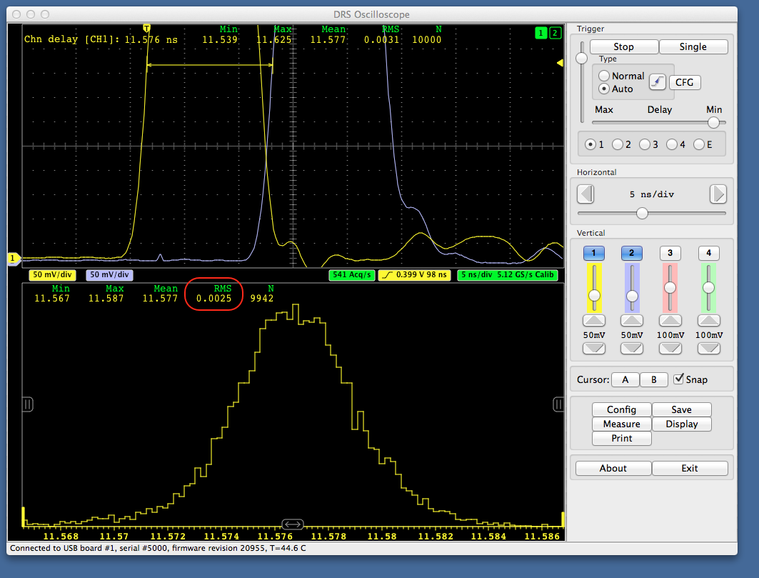
Using more sophisticated algorithms such as cross-correlation, resolutions below 1 ps were already achieved.
The new board can now be ordered at the same price than the V4 board, delivery will start in March 2014.
Best regards,
Stefan Ritt
|
|
322
|
Thu Jan 9 11:02:46 2014 |
Stefan Ritt | v5 software with v4 board calibration |
| Martin Petriska wrote: |
|
Hi
Question:
In v4 board, which channel has best calibration ?
Should it be possible to simulate v5 board and read calibration values for v4 board by other method .. for example using external calibration signal source connected to all channels?
Is it needed to detach all input signals from EVM board during calibration ?( I see there are switches on channel inputs.)
Some comments: averager.h, averager.cpp are missing in windows v.5 sources (it should be copied from linux sources)
PF2014 and thank You for development new EVM 5 and new time precision.
Martin
|
In v4 board, actually no channel has a good calibration. The timing calibration is done with channel #9, which is hard connected to a (poor) clock. So the best you can get there is ~30 ps. In principle one can calibrate the V4 board with an external source. The problem there is to find a good sine wave oscillator (we have several expensive ones and only one was good enough), and that the software does not support this. You would have to write your own calibration code (where of course you can "recycle" the one from the V5 software.
Thanks for pointing out the missing averager.*, I will add it.
/Stefan |
|
321
|
Thu Jan 9 10:58:19 2014 |
Martin Petriska | v5 software with v4 board calibration | Hi
Question:
In v4 board, which channel has best calibration ?
Should it be possible to simulate v5 board and read calibration values for v4 board by other method .. for example using external calibration signal source connected to all channels?
Is it needed to detach all input signals from EVM board during calibration ?( I see there are switches on channel inputs.)
Some comments: averager.h, averager.cpp are missing in windows v.5 sources (it should be copied from linux sources)
PF2014 and thank You for development new EVM 5 and new time precision.
Martin |
|