| ID |
Date |
Author |
Subject |
|
260
|
Mon Jun 10 14:09:13 2013 |
tmiron alon | add an average ability to the Scope |
| Stefan Ritt wrote: |
|
| tmiron alon wrote: |
|
Hallo,
I'm using DRS4 Evaluation Board Rev 4.0 and I'm trying to change the output of the samples to be an average of # measurements (1000 or even more)
during the process I have encountered some difficulties I hope you will be able to help me with:
1. the DRS chip have 8 channels but the Evaluation board have only 4 channels. does the default mode of the DRS in the Evaluation Board is 1024 bins for each channel or 2048?
2. in the readout mode, does it samples all the 1024 bins waveform from a channel and then move to the next one, or after each bin it move to the next channel?
3. In the file "drs4_eval4_app.vhd", I have a problem finding the names of the signals that represents the registers bits which tell me what is the number of the bin (1-1024) the ADC is reading from the DRS, and the signals
that represents registers A0-A3. can you send me their names?
4. In another matter- is the -0.5V to 0.5V is the upper and lower limit of the input (or just a working range), and if not what is the limit for AC? is there a fuse on the board in case of overload from the input? (I didn't see it in the User's Manual, but I didn't know if you will mention it there in case there is one).
thanks in advance and have a nice day,
Tmiron
|
1. All 8 channels are read out, but only 4 are displayed in the oscilloscope.
2. It reads all 1024 bins from a channel, then switch to the next channel.
3. The ADC readout happens in lines 1576+. The register for the sample count is drs_sample_count, and the signal for the address is drs_addr.
4. The evaluation board manual explicitly mentions the maximum allowed input range on page 5.
/Stefan
|
Hi Stefan,
I'm trying to add the averaging feature to the oscilloscope instead. I have a basic knowledge in C++ so I'm having problem finding the initial place (places) of the data acquisition. furthermore, I saw you already made an averaging possibility for some of the features in the program at the measure window.
Can you please tell we in which of the programs of the Scope (and in what line if possible) can I find the initial\main data acquisition so I could follow it from there, and where is the location of the averaging function you already made?
have a nice week,
Tmiron
|
|
259
|
Fri Jun 7 11:44:17 2013 |
tmiron alon | thank you |
| Stefan Ritt wrote: |
|
| tmiron alon wrote: |
|
Hallo,
I'm using DRS4 Evaluation Board Rev 4.0 and I'm trying to change the output of the samples to be an average of # measurements (1000 or even more)
during the process I have encountered some difficulties I hope you will be able to help me with:
1. the DRS chip have 8 channels but the Evaluation board have only 4 channels. does the default mode of the DRS in the Evaluation Board is 1024 bins for each channel or 2048?
2. in the readout mode, does it samples all the 1024 bins waveform from a channel and then move to the next one, or after each bin it move to the next channel?
3. In the file "drs4_eval4_app.vhd", I have a problem finding the names of the signals that represents the registers bits which tell me what is the number of the bin (1-1024) the ADC is reading from the DRS, and the signals
that represents registers A0-A3. can you send me their names?
4. In another matter- is the -0.5V to 0.5V is the upper and lower limit of the input (or just a working range), and if not what is the limit for AC? is there a fuse on the board in case of overload from the input? (I didn't see it in the User's Manual, but I didn't know if you will mention it there in case there is one).
thanks in advance and have a nice day,
Tmiron
|
1. All 8 channels are read out, but only 4 are displayed in the oscilloscope.
2. It reads all 1024 bins from a channel, then switch to the next channel.
3. The ADC readout happens in lines 1576+. The register for the sample count is drs_sample_count, and the signal for the address is drs_addr.
4. The evaluation board manual explicitly mentions the maximum allowed input range on page 5.
/Stefan
|
Thank you for the answer.
Have a nice week,
Tmiron. |
|
258
|
Fri Jun 7 10:22:48 2013 |
Stefan Ritt | |
| tmiron alon wrote: |
|
Hallo,
I'm using DRS4 Evaluation Board Rev 4.0 and I'm trying to change the output of the samples to be an average of # measurements (1000 or even more)
during the process I have encountered some difficulties I hope you will be able to help me with:
1. the DRS chip have 8 channels but the Evaluation board have only 4 channels. does the default mode of the DRS in the Evaluation Board is 1024 bins for each channel or 2048?
2. in the readout mode, does it samples all the 1024 bins waveform from a channel and then move to the next one, or after each bin it move to the next channel?
3. In the file "drs4_eval4_app.vhd", I have a problem finding the names of the signals that represents the registers bits which tell me what is the number of the bin (1-1024) the ADC is reading from the DRS, and the signals
that represents registers A0-A3. can you send me their names?
4. In another matter- is the -0.5V to 0.5V is the upper and lower limit of the input (or just a working range), and if not what is the limit for AC? is there a fuse on the board in case of overload from the input? (I didn't see it in the User's Manual, but I didn't know if you will mention it there in case there is one).
thanks in advance and have a nice day,
Tmiron
|
1. All 8 channels are read out, but only 4 are displayed in the oscilloscope.
2. It reads all 1024 bins from a channel, then switch to the next channel.
3. The ADC readout happens in lines 1576+. The register for the sample count is drs_sample_count, and the signal for the address is drs_addr.
4. The evaluation board manual explicitly mentions the maximum allowed input range on page 5.
/Stefan |
|
257
|
Sun May 26 13:08:52 2013 |
tmiron alon | | Hallo,
I'm using DRS4 Evaluation Board Rev 4.0 and I'm trying to change the output of the samples to be an average of # measurements (1000 or even more)
during the process I have encountered some difficulties I hope you will be able to help me with:
1. the DRS chip have 8 channels but the Evaluation board have only 4 channels. does the default mode of the DRS in the Evaluation Board is 1024 bins for each channel or 2048?
2. in the readout mode, does it samples all the 1024 bins waveform from a channel and then move to the next one, or after each bin it move to the next channel?
3. In the file "drs4_eval4_app.vhd", I have a problem finding the names of the signals that represents the registers bits which tell me what is the number of the bin (1-1024) the ADC is reading from the DRS, and the signals
that represents registers A0-A3. can you send me their names?
4. In another matter- is the -0.5V to 0.5V is the upper and lower limit of the input (or just a working range), and if not what is the limit for AC? is there a fuse on the board in case of overload from the input? (I didn't see it in the User's Manual, but I didn't know if you will mention it there in case there is one).
thanks in advance and have a nice day,
Tmiron |
|
256
|
Sat May 25 21:03:22 2013 |
Stefan Ritt | DRS4- analog pulse counting |
| Osip Lishilin wrote: |
|
| Stefan Ritt wrote: |
|
| Osip Lishilin wrote: |
|
Hello, Stefan. Have you implemented pulse counting yet?
Best, Osip.
|
Nope.
|
Will it be done in the foreseeable future?
|
Yes. I will announce it in the forum. |
|
255
|
Sat May 25 12:45:46 2013 |
Enrico Conti | mac osx 10.6 | > > I made some progress. Understood what was wrong in the make phase. You have only to add the option -arch i386 in the CFLAGS line of the makefile.
> > Then the make is ok, it produces the 3 executables. drs_exam and drscl seem to work correctly.
> > DRSOsc.app does not work as app, in the sense that if you click it, an error message comes saying "You can't use this version of the application DRSOsc.app with
> > this version of Mac OS X. You have Mac OSX 10.6.8. The application requires Mac OS X 10.7 or later. "
> > If you execute drsosc from the terminal, the graphical window pops up, the waveform is displayed, but you don't have access to the graphical interface, no button works, you can't do
> > anything. To quit the app, you have to kill it from the terminal with the kill command.
>
> To run an executable as an app, you have to put it into a certain directory structure. The Makefile has the target "make app" which exactly does that. It executes following code:
>
> DRSOsc.app: drsosc
> -mkdir DRSOsc.app
> -mkdir DRSOsc.app/Contents
> -mkdir DRSOsc.app/Contents/MacOS
> -mkdir DRSOsc.app/Contents/Resources
> -mkdir DRSOsc.app/Contents/Resources/English.lproj
> echo 'APPL????' > DRSOsc.app/Contents/PkgInfo
> cp drsosc.xcodeproj/Info-processed.plist DRSOsc.app/Contents/Info.plist
> cp drsosc DRSOsc.app/Contents/MacOS/DRSOsc
> cp drsosc.xcodeproj/DRSOsc.icns DRSOsc.app/Contents/Resources
>
> You can also do this manually. You will then see the subdirectly DRSOsc.app actually as an App icon (you don't see it as a subdirectory in the Finder). That's the way Apple has chosen to do this.
>
> The chip test facility has been made for a certain test board we use for chip testing. It has a feature that is not present in the evaluation board. I have to disable that command there.
>
> Best regards,
> Stefan
Hi Stefan,
yes, the makefile has already the recipe to create the app. For OSX 10.6 a obvious modification must be done in the info.plist file. Then everything goes right. Now I have the DRSOsc application
running on my mac with 10.6.
Thanks for the help.
Best regards,
Enrico |
|
254
|
Fri May 24 18:20:14 2013 |
Stefan Ritt | mac osx 10.6 | > I made some progress. Understood what was wrong in the make phase. You have only to add the option -arch i386 in the CFLAGS line of the makefile.
> Then the make is ok, it produces the 3 executables. drs_exam and drscl seem to work correctly.
> DRSOsc.app does not work as app, in the sense that if you click it, an error message comes saying "You can't use this version of the application DRSOsc.app with
> this version of Mac OS X. You have Mac OSX 10.6.8. The application requires Mac OS X 10.7 or later. "
> If you execute drsosc from the terminal, the graphical window pops up, the waveform is displayed, but you don't have access to the graphical interface, no button works, you can't do
> anything. To quit the app, you have to kill it from the terminal with the kill command.
To run an executable as an app, you have to put it into a certain directory structure. The Makefile has the target "make app" which exactly does that. It executes following code:
DRSOsc.app: drsosc
-mkdir DRSOsc.app
-mkdir DRSOsc.app/Contents
-mkdir DRSOsc.app/Contents/MacOS
-mkdir DRSOsc.app/Contents/Resources
-mkdir DRSOsc.app/Contents/Resources/English.lproj
echo 'APPL????' > DRSOsc.app/Contents/PkgInfo
cp drsosc.xcodeproj/Info-processed.plist DRSOsc.app/Contents/Info.plist
cp drsosc DRSOsc.app/Contents/MacOS/DRSOsc
cp drsosc.xcodeproj/DRSOsc.icns DRSOsc.app/Contents/Resources
You can also do this manually. You will then see the subdirectly DRSOsc.app actually as an App icon (you don't see it as a subdirectory in the Finder). That's the way Apple has chosen to do this.
The chip test facility has been made for a certain test board we use for chip testing. It has a feature that is not present in the evaluation board. I have to disable that command there.
Best regards,
Stefan |
|
253
|
Fri May 24 17:58:07 2013 |
Enrico Conti | mac osx 10.6 | > > >
> > > it looks like 64bit vs 32bit problem, you have to compile all libraries for the same architecture. Maybe, make clean to
> > > remove all precompiled object files .o and recompile it again. Try to compile first that simple example without wxWidgets.
> > >
> > > Martin
> >
> >
> > Good point, but all libraries are already compiled to 32 bits, since the laptop is running at 32 bits. Unless you mean that I
> > have to convert to 64 bits, but this means to change all content of the PC, and I don't want to do this. Can the applications
> > run with 32 bits or do they need 64 ?
> >
> > Thanks,
> > Enrico
>
> There is no specific reason to run it on 64 bits, so just all libraries have to match, that's all. But the original Makefile has been written for 64 bits, so it might need some
> adjustments.
>
> /Stefan
Hi Stefan,
I made some progress. Understood what was wrong in the make phase. You have only to add the option -arch i386 in the CFLAGS line of the makefile.
Then the make is ok, it produces the 3 executables. drs_exam and drscl seem to work correctly.
DRSOsc.app does not work as app, in the sense that if you click it, an error message comes saying "You can't use this version of the application DRSOsc.app with
this version of Mac OS X. You have Mac OSX 10.6.8. The application requires Mac OS X 10.7 or later. "
If you execute drsosc from the terminal, the graphical window pops up, the waveform is displayed, but you don't have access to the graphical interface, no button works, you can't do
anything. To quit the app, you have to kill it from the terminal with the kill command.
But anyway is a progress with respect to yestarday.
Any idea/suggestion to overcome the above problems ? I thought it is a problem with the graphical library (xwWidgets) but I have checked it, it's ok, I have also reinstalled it
(release 2.8.12_3) but nothing changed.
PS. the chip test output (done with the drscl ) is the following (see below). Is it normal or what ? THANKS.
B0> ct
Press 'q' to quit, any other key to repeat test.
Max. frequency is 5.1 GHz
Cell error on channel 1, cell 5: -137.6 mV instead 0 mV
Chip Error!
Max. frequency is 5.1 GHz
Cell error on channel 1, cell 5: -129.4 mV instead 0 mV
Chip Error! |
|
252
|
Tue May 21 18:30:11 2013 |
Enrico Conti | mac osx 10.6 | > > >
> > > it looks like 64bit vs 32bit problem, you have to compile all libraries for the same architecture. Maybe, make clean to
> > > remove all precompiled object files .o and recompile it again. Try to compile first that simple example without wxWidgets.
> > >
> > > Martin
> >
> >
> > Good point, but all libraries are already compiled to 32 bits, since the laptop is running at 32 bits. Unless you mean that I
> > have to convert to 64 bits, but this means to change all content of the PC, and I don't want to do this. Can the applications
> > run with 32 bits or do they need 64 ?
> >
> > Thanks,
> > Enrico
>
> There is no specific reason to run it on 64 bits,
Good.
> so just all libraries have to match, that's all. But the original Makefile has been written for 64 bits, so it might need some
> adjustments.
Ok, but I don't understand where is the point to correct. 64 bits do not appear explicitally (at least to me, who am not a drake of programming ...)
neither in the Makefile neither in the (few) source files I have examined.
Thanks again,
Enrico |
|
251
|
Tue May 21 17:51:09 2013 |
Stefan Ritt | mac osx 10.6 | > >
> > it looks like 64bit vs 32bit problem, you have to compile all libraries for the same architecture. Maybe, make clean to
> > remove all precompiled object files .o and recompile it again. Try to compile first that simple example without wxWidgets.
> >
> > Martin
>
>
> Good point, but all libraries are already compiled to 32 bits, since the laptop is running at 32 bits. Unless you mean that I
> have to convert to 64 bits, but this means to change all content of the PC, and I don't want to do this. Can the applications
> run with 32 bits or do they need 64 ?
>
> Thanks,
> Enrico
There is no specific reason to run it on 64 bits, so just all libraries have to match, that's all. But the original Makefile has been written for 64 bits, so it might need some
adjustments.
/Stefan |
|
250
|
Tue May 21 17:48:45 2013 |
Enrico Conti | mac osx 10.6 | >
> it looks like 64bit vs 32bit problem, you have to compile all libraries for the same architecture. Maybe, make clean to
> remove all precompiled object files .o and recompile it again. Try to compile first that simple example without wxWidgets.
>
> Martin
Good point, but all libraries are already compiled to 32 bits, since the laptop is running at 32 bits. Unless you mean that I
have to convert to 64 bits, but this means to change all content of the PC, and I don't want to do this. Can the applications
run with 32 bits or do they need 64 ?
Thanks,
Enrico |
|
249
|
Tue May 21 17:45:05 2013 |
Enrico Conti | mac osx 10.6 | >
> Can it be that you have a old PowerPC MAC? I have no experience with that, but probably you have to adjust the Makefile
> ans set some flags correctly for PPC instead of Intel.
>
> /Stefan
No, I have a MacBook Pro 2.8 GHz Intel Core 2 Duo. |
|
248
|
Tue May 21 13:32:13 2013 |
Martin Petriska | mac osx 10.6 | > Hi,
>
> I would like to use the DRS4 with my macbook pro running osx 10.6.8.
> I have installed the wxWidgets and the libusb-1.0 libraries and I am using the Linux code vers. 4.0.1. After
> compilation, the following errors come out:
>
> ld: warning: in musbstd.o, file was built for unsupported file format which is not the architecture being linked
> (i386)
> ld: warning: in mxml.o, file was built for unsupported file format which is not the architecture being linked (i386)
> ....
> ....
> ld: warning: in main.o, file was built for unsupported file format which is not the architecture being linked (i386)
> Undefined symbols:
> "_main", referenced from:
> start in crt1.10.6.o
> ld: symbol(s) not found
> collect2: ld returned 1 exit status
> make: *** [drsosc] Error 1
>
>
> Do you have any idea on how to solve the problem ?? or maybe do you have a package working with osx 10.6 ? I
> remember to have seen, long time ago, a package that could work with 10.6 (or 10.5 ?), but I cannot find it now
> (but maybe I remember wrong).
>
> Thanks for any help,
>
> Enrico
it looks like 64bit vs 32bit problem, you have to compile all libraries for the same architecture. Maybe, make clean to
remove all precompiled object files .o and recompile it again. Try to compile first that simple example without wxWidgets.
Martin |
|
247
|
Tue May 21 13:25:41 2013 |
Stefan Ritt | mac osx 10.6 | > Hi,
>
> I would like to use the DRS4 with my macbook pro running osx 10.6.8.
> I have installed the wxWidgets and the libusb-1.0 libraries and I am using the Linux code vers. 4.0.1. After
> compilation, the following errors come out:
>
> ld: warning: in musbstd.o, file was built for unsupported file format which is not the architecture being linked
> (i386)
> ld: warning: in mxml.o, file was built for unsupported file format which is not the architecture being linked (i386)
> ....
> ....
> ld: warning: in main.o, file was built for unsupported file format which is not the architecture being linked (i386)
> Undefined symbols:
> "_main", referenced from:
> start in crt1.10.6.o
> ld: symbol(s) not found
> collect2: ld returned 1 exit status
> make: *** [drsosc] Error 1
>
>
> Do you have any idea on how to solve the problem ?? or maybe do you have a package working with osx 10.6 ? I
> remember to have seen, long time ago, a package that could work with 10.6 (or 10.5 ?), but I cannot find it now
> (but maybe I remember wrong).
>
> Thanks for any help,
>
> Enrico
Can it be that you have a old PowerPC MAC? I have no experience with that, but probably you have to adjust the Makefile
ans set some flags correctly for PPC instead of Intel.
/Stefan |
|
246
|
Tue May 21 12:39:00 2013 |
Enrico Conti | mac osx 10.6 | Hi,
I would like to use the DRS4 with my macbook pro running osx 10.6.8.
I have installed the wxWidgets and the libusb-1.0 libraries and I am using the Linux code vers. 4.0.1. After
compilation, the following errors come out:
ld: warning: in musbstd.o, file was built for unsupported file format which is not the architecture being linked
(i386)
ld: warning: in mxml.o, file was built for unsupported file format which is not the architecture being linked (i386)
....
....
ld: warning: in main.o, file was built for unsupported file format which is not the architecture being linked (i386)
Undefined symbols:
"_main", referenced from:
start in crt1.10.6.o
ld: symbol(s) not found
collect2: ld returned 1 exit status
make: *** [drsosc] Error 1
Do you have any idea on how to solve the problem ?? or maybe do you have a package working with osx 10.6 ? I
remember to have seen, long time ago, a package that could work with 10.6 (or 10.5 ?), but I cannot find it now
(but maybe I remember wrong).
Thanks for any help,
Enrico |
|
245
|
Mon May 20 08:42:16 2013 |
Osip Lishilin | DRS4- analog pulse counting |
| Stefan Ritt wrote: |
|
| Osip Lishilin wrote: |
|
Hello, Stefan. Have you implemented pulse counting yet?
Best, Osip.
|
Nope.
|
Will it be done in the foreseeable future? |
|
244
|
Wed May 8 19:50:01 2013 |
Andrey Kuznetsov | DRS4 installation on Windows 8 issues | I'm also having trouble installing drivers and running DRSOsc program on another computer running Windows 8.
The issue with the driver is that it's not digitally signed.
The issue with the DRSOsc is that it's failing to find libusb0.dll. libusb-win32 seemed to have installed upon DRS4 software install, however the supplied version is Windows 7/8 incompatible, so on Windows 7 computer I had to download libusb_win32 v1.2.6.0 from the official website and install it directly, then everything worked fine. However in Windows 8, I am unable to install libusb-win32 because in libusb-win32 Inf Wizard installation program when you select for which device the libusb should be used, it asks to install a driver, but when I point to DRS' driver, it says "Unknown Error: 1" and that's that. One way around the libusb issue is to copy the required dll and sys file directly where the .exe is stored.
I will attempt to disable signed driver signature requirement, and see if the driver installs then, but this should really be fixed instead. |
|
243
|
Wed May 8 06:07:52 2013 |
Andrey Kuznetsov | DRS4 v2.0 Eval Board running on higher versions of DRS Oscilloscope program | Hi,
I have an old v2.0 board that I just upgraded firmware on using v4.0.0 download package which has a drs4_eval1.bit for v2.0 boards containing firmware 15158. So I would like to use the latest DRS Oscilloscope program, due to the faster acquisition speeds and advanced calibration techniques, however I seem to be running into a problem.
v4.0 DRS Oscilloscope program displays flat lines in any configuration instead of a pulse that I provide to it (I can't tell if calibration works because all my traces are flat and nothing triggers) but provides ~460Hz. Any idea why v4.0.0 DRS Oscilloscope program does not work with DRS4 Eval Board v2.0 fw:15158?
v3.0 DRS Oscilloscope program actually works and displays the pulse that I input (calibration also works), however it only has 64Hz speed due to v3.0.0 not having multithreading capability which is provided in v3.1.0 software version of the program.
Can you please upload and post on the website the latest software packages for v2 and v3? I would like to use v3.1.0 DRS Oscilloscope version. (Both Linux and Windows, but Linux preferably)
Also, I would like to report that for some reason, I don't know if it happens with v3.0 program used on v2.0 board only or a general issue, but after each calibration of voltage and timing, the trigger does not work. I have to exit the oscilloscope program, and run it again, then the trigger works fine, and the device is calibrated.
Thank you |
|
242
|
Mon Apr 22 15:52:53 2013 |
Stefan Ritt | effect of jitter/alignment between SRCLK and ADC clock |
| Benjamin LeGeyt wrote: |
|
Hello!
let me apologize in advance if this has already been covered somewhere and I missed it.
I have a question about a statement made regarding the ADC clock in the evaluation board v4.0 manual. At the bottom or page 23 there is a mention of jitter between the SRCLK signal and the ADC clock causing a baseline variation in the sampled output of up to a few mV. Is there any more information out there about this? I find this confusing for the following reason: If the DRS output has mostly settled after 28ns and the signal that is being sampled is a DC signal, I don't understand why an aperture jitter in the sampling ADC should cause a voltage error in the measured signal. I already know about the possibility of noise spikes every 32 samples if these clocks are not properly aligned, though I don't know the origin of those spikes. are these two things related?
Many Thanks!
|
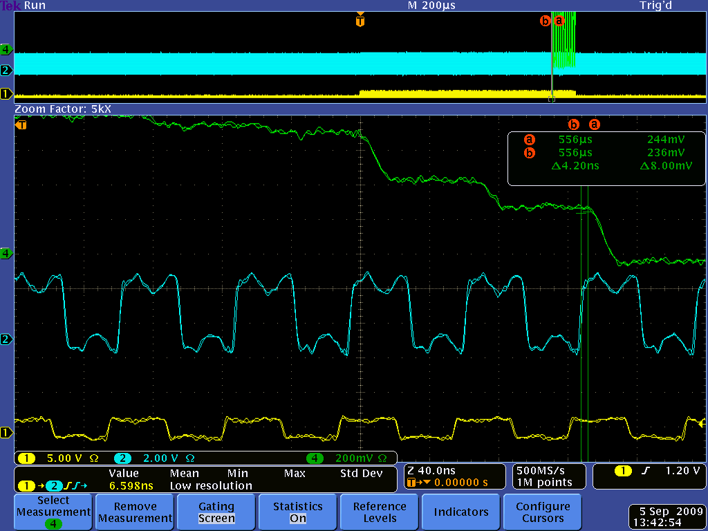
Hi Benjamin,
In principle you are right, for a DC signal that should not matter. But in reality the DRS4 output signal is not constant even for a DC signal. When you switch from one sampling cell to another during readout, there is something called "charge injection". This causes the output to change up to several 10 mV. After 28 ns this is mostly settled, but not completely, since the DRS4 output driver has a relatively low bandwidth (~50 MHz). Furthermore, the signal line between the DRS4 and the ADC is not terminated, so you have some reflections going forth and back. In addition, you have some crosstalk from the SRCLK signal. So it's better that you sample on each cycle at exactly the same time. Here you see a plot of that (green: DRS4 output, blue: ADC clock, yellow SRCLK):
|
|
241
|
Mon Apr 22 15:33:28 2013 |
Benjamin LeGeyt | effect of jitter/alignment between SRCLK and ADC clock | Hello!
let me apologize in advance if this has already been covered somewhere and I missed it.
I have a question about a statement made regarding the ADC clock in the evaluation board v4.0 manual. At the bottom or page 23 there is a mention of jitter between the SRCLK signal and the ADC clock causing a baseline variation in the sampled output of up to a few mV. Is there any more information out there about this? I find this confusing for the following reason: If the DRS output has mostly settled after 28ns and the signal that is being sampled is a DC signal, I don't understand why an aperture jitter in the sampling ADC should cause a voltage error in the measured signal. I already know about the possibility of noise spikes every 32 samples if these clocks are not properly aligned, though I don't know the origin of those spikes. are these two things related?
Many Thanks!
|
|