| ID |
Date |
Author |
Subject |
|
554
|
Tue Nov 8 10:20:52 2016 |
Stefan Ritt | Missing Header | The web page from where you downloaded the software contains a sentence "requires libusb-1.0 package". Please install it. This package brings the "usb.h" header file.
Stefan
| Christian Farina wrote: |
|
Hello everybody,
I am completely new to this, so please bear with me.
I am trying to install the applications on my laptop. I downloaded and untar-ed the drivers and applications for Linux as described in the evaluation board manual. However, when I do the make, I get the following error:
drs-4.0.0$ make
g++ -g -O2 -Wall -Wuninitialized -fno-strict-aliasing -Iinclude -DOS_LINUX -DHAVE_LIBUSB -DUSE_DRS_MUTEX -c src/musbstd.c
In file included from src/musbstd.c:14:0:
include/musbstd.h:17:17: fatal error: usb.h: No such file or directory
#include <usb.h>
Can anybody help me please?
Thanks.
|
|
|
555
|
Wed Nov 9 17:19:48 2016 |
Christian Farina | Missing Header | Thank you Stefan, that was just what I needed.
Also, I have another question, if I am allowed to ask on this forum. I am trying to study how the time calibration of the DRS is done. Can you point me to the script in which this is done?
Thank you,
Christian
| Stefan Ritt wrote: |
|
The web page from where you downloaded the software contains a sentence "requires libusb-1.0 package". Please install it. This package brings the "usb.h" header file.
Stefan
| Christian Farina wrote: |
|
Hello everybody,
I am completely new to this, so please bear with me.
I am trying to install the applications on my laptop. I downloaded and untar-ed the drivers and applications for Linux as described in the evaluation board manual. However, when I do the make, I get the following error:
drs-4.0.0$ make
g++ -g -O2 -Wall -Wuninitialized -fno-strict-aliasing -Iinclude -DOS_LINUX -DHAVE_LIBUSB -DUSE_DRS_MUTEX -c src/musbstd.c
In file included from src/musbstd.c:14:0:
include/musbstd.h:17:17: fatal error: usb.h: No such file or directory
#include <usb.h>
Can anybody help me please?
Thanks.
|
|
|
|
556
|
Wed Nov 9 19:49:07 2016 |
Stefan Ritt | Missing Header | Best is to read this paper: https://arxiv.org/abs/1405.4975
The source code for that is in DRS.cpp in the DRS software distribution in the function DRSBoard::CalibrateTiming()
Stefan
| Christian Farina wrote: |
|
Thank you Stefan, that was just what I needed.
Also, I have another question, if I am allowed to ask on this forum. I am trying to study how the time calibration of the DRS is done. Can you point me to the script in which this is done?
Thank you,
Christian
| Stefan Ritt wrote: |
|
The web page from where you downloaded the software contains a sentence "requires libusb-1.0 package". Please install it. This package brings the "usb.h" header file.
Stefan
| Christian Farina wrote: |
|
Hello everybody,
I am completely new to this, so please bear with me.
I am trying to install the applications on my laptop. I downloaded and untar-ed the drivers and applications for Linux as described in the evaluation board manual. However, when I do the make, I get the following error:
drs-4.0.0$ make
g++ -g -O2 -Wall -Wuninitialized -fno-strict-aliasing -Iinclude -DOS_LINUX -DHAVE_LIBUSB -DUSE_DRS_MUTEX -c src/musbstd.c
In file included from src/musbstd.c:14:0:
include/musbstd.h:17:17: fatal error: usb.h: No such file or directory
#include <usb.h>
Can anybody help me please?
Thanks.
|
|
|
|
|
561
|
Thu Nov 10 20:54:45 2016 |
Christian Farina | Missing Header | Hi Stefan,
I have already read the paper. I was just unsure where the calibration code was located. Thank you so much for all your help.
Christian
| Stefan Ritt wrote: |
|
Best is to read this paper: https://arxiv.org/abs/1405.4975
The source code for that is in DRS.cpp in the DRS software distribution in the function DRSBoard::CalibrateTiming()
Stefan
| Christian Farina wrote: |
|
Thank you Stefan, that was just what I needed.
Also, I have another question, if I am allowed to ask on this forum. I am trying to study how the time calibration of the DRS is done. Can you point me to the script in which this is done?
Thank you,
Christian
| Stefan Ritt wrote: |
|
The web page from where you downloaded the software contains a sentence "requires libusb-1.0 package". Please install it. This package brings the "usb.h" header file.
Stefan
| Christian Farina wrote: |
|
Hello everybody,
I am completely new to this, so please bear with me.
I am trying to install the applications on my laptop. I downloaded and untar-ed the drivers and applications for Linux as described in the evaluation board manual. However, when I do the make, I get the following error:
drs-4.0.0$ make
g++ -g -O2 -Wall -Wuninitialized -fno-strict-aliasing -Iinclude -DOS_LINUX -DHAVE_LIBUSB -DUSE_DRS_MUTEX -c src/musbstd.c
In file included from src/musbstd.c:14:0:
include/musbstd.h:17:17: fatal error: usb.h: No such file or directory
#include <usb.h>
Can anybody help me please?
Thanks.
|
|
|
|
|
|
269
|
Fri Jul 5 12:46:45 2013 |
Hermann-Josef Mathes | Missing methods in drs-4.0.1.tar.gz | Hi,
while trying to create python bindings for the DRS stuff using SWIG 2.0.4, two undefined methods prevent the python interpreter from loading the generated shared library. These methods are:
- int DRSBoard::SetADCActive(unsigned char)
- bool ResponseCalibration::Calibrate(unsigned int,unsigned int,float *,float *,float,bool)
Can we safely removed those methods from the DRS header files or (what I have actually done) is it better to fake some empty implementation in the input file to SWIG?
Another minor issue is that the python interpreter always terminates with a SegFault after script termination. I had not yet time to track that down...
Thanks & regards
Hermann-Josef
|
|
270
|
Sat Jul 6 06:10:38 2013 |
Stefan Ritt | Missing methods in drs-4.0.1.tar.gz |
| Hermann-Josef Mathes wrote: |
|
Hi,
while trying to create python bindings for the DRS stuff using SWIG 2.0.4, two undefined methods prevent the python interpreter from loading the generated shared library. These methods are:
- int DRSBoard::SetADCActive(unsigned char)
- bool ResponseCalibration::Calibrate(unsigned int,unsigned int,float *,float *,float,bool)
Can we safely removed those methods from the DRS header files or (what I have actually done) is it better to fake some empty implementation in the input file to SWIG?
Another minor issue is that the python interpreter always terminates with a SegFault after script termination. I had not yet time to track that down...
Thanks & regards
Hermann-Josef
|
Thanks for pointing that out. My C++ compiler does not complain about such errors. You can safely remove these functions. I did so as well, so future versions will not contain that any more.
/Stefan |
|
706
|
Thu Jun 28 19:55:45 2018 |
Woon-Seng Choong | Negative Bin Width | I am using a DRS4 Evaluation Board v5 and running the drsosc.exe version 5.06 on a Window 7 machine. I have performed the voltage and timing calibration.
With test pulses on channel 1 and 2, I collected binary data file with all 4 channels active sampling at 5GSPS.
Attached is a distribution of the bin_width vs. cell # for all the 4 channels. Note that there are few cells with bin_width < 10 ps.
Channel 1: bin_width[498] = -0.000348, bin_width[1010]= -0.000348
Channel 2: bin_width[498] = 0.007363
Channel 3: bin_width[498] = 0.007843
Channel 4: bin_width[498] = 0.005948
Is this normal? How can you get negative bin_width? What does negative bin_width means?
I have attached the binary data file for your verification.
|
|
707
|
Fri Jun 29 07:51:33 2018 |
Stefan Ritt | Negative Bin Width | Yes that's normal. A negative cell bin width means that the next cell N+1 samples the input signal before cell N. This can happen due to the signal routing on the DRS4 chip.
Stefan
| Woon-Seng Choong wrote: |
|
I am using a DRS4 Evaluation Board v5 and running the drsosc.exe version 5.06 on a Window 7 machine. I have performed the voltage and timing calibration.
With test pulses on channel 1 and 2, I collected binary data file with all 4 channels active sampling at 5GSPS.
Attached is a distribution of the bin_width vs. cell # for all the 4 channels. Note that there are few cells with bin_width < 10 ps.
Channel 1: bin_width[498] = -0.000348, bin_width[1010]= -0.000348
Channel 2: bin_width[498] = 0.007363
Channel 3: bin_width[498] = 0.007843
Channel 4: bin_width[498] = 0.005948
Is this normal? How can you get negative bin_width? What does negative bin_width means?
I have attached the binary data file for your verification.
|
|
|
509
|
Thu Apr 21 22:16:43 2016 |
Kyle Weinfurther | Negative fCellDT values from GetTimeCalibration() | Hello Stefan,
I am using four DRS4 v5 eval boards to digitize 16 channels of data. I have recently changed from saving the timing information of the waveform using GetTime() to GetTimeCalibration(). When changing over, I noticed that some values for fCellDT for cell 498 are negative. Over the 16 channels used, 4 of them have negative time bin widths for cell 498 while the other 12 channels are very close to 0 (in the ~10 ps range). One of the eval boards has no negative fCellDT whereas the other three boards have one or two channels with negative values.
Upon further inspection, I checked the time between samples of GetTime() and found the same results in cell 498. After finding this, I did a timing calibration again with CalibrateTiming() even though in a different post on the discussion forum you said it was valid for a wide range of temperatures and a long time (years). This still allowed the negative fCellDT values to persist.
Is this a common occurance? If so, is there a method to fix this issue? Is there a reason for cell 498 to have a small value for fCellDT? I searched the discussion forum and did not find anything relating to this issue.
Attached are a couple waveform traces using GetTime() zoomed in on cell 498.
Thanks,
Kyle Weinfurther |
|
511
|
Sat Apr 23 12:33:17 2016 |
Daniel Stricker-Shaver | Negative fCellDT values from GetTimeCalibration() | Hi Kyle,
If I remember right the negative sampling width happens only for 498 and at high sampling speeds. It is described in a paper from Stefan:
http://arxiv.org/pdf/1405.4975.pdf
or
“Novel Calibration Method for Switched Capacitor Arrays Enables Time Measurements With Sub-Picosecond Resolution”( IEEE Transactions on Nuclear Science 61 (2014),Nr. 6, 3607–3617)
| Kyle Weinfurther wrote: |
|
Hello Stefan,
I am using four DRS4 v5 eval boards to digitize 16 channels of data. I have recently changed from saving the timing information of the waveform using GetTime() to GetTimeCalibration(). When changing over, I noticed that some values for fCellDT for cell 498 are negative. Over the 16 channels used, 4 of them have negative time bin widths for cell 498 while the other 12 channels are very close to 0 (in the ~10 ps range). One of the eval boards has no negative fCellDT whereas the other three boards have one or two channels with negative values.
Upon further inspection, I checked the time between samples of GetTime() and found the same results in cell 498. After finding this, I did a timing calibration again with CalibrateTiming() even though in a different post on the discussion forum you said it was valid for a wide range of temperatures and a long time (years). This still allowed the negative fCellDT values to persist.
Is this a common occurance? If so, is there a method to fix this issue? Is there a reason for cell 498 to have a small value for fCellDT? I searched the discussion forum and did not find anything relating to this issue.
Attached are a couple waveform traces using GetTime() zoomed in on cell 498.
Thanks,
Kyle Weinfurther
|
|
|
512
|
Tue Apr 26 09:54:16 2016 |
Stefan Ritt | Negative fCellDT values from GetTimeCalibration() | I just realized that the negative bin widht is not explicitly mentioned in the quoted paper. So let me explain it here:
The negative value of cell 498 is correct and "real" in the sense that the signal is first captured in cell 498 and later in cell 497. This is due to the exact layout of the cells on the chip and the input signal. Cell 498 is simply much closer to the input, so sees the signal earlier than cell 497, even if it's triggerd after cell 497. So nothing to worry about.
Stefan
| Daniel Stricker-Shaver wrote: |
|
Hi Kyle,
If I remember right the negative sampling width happens only for 498 and at high sampling speeds. It is described in a paper from Stefan:
http://arxiv.org/pdf/1405.4975.pdf
or
“Novel Calibration Method for Switched Capacitor Arrays Enables Time Measurements With Sub-Picosecond Resolution”( IEEE Transactions on Nuclear Science 61 (2014),Nr. 6, 3607–3617)
| Kyle Weinfurther wrote: |
|
Hello Stefan,
I am using four DRS4 v5 eval boards to digitize 16 channels of data. I have recently changed from saving the timing information of the waveform using GetTime() to GetTimeCalibration(). When changing over, I noticed that some values for fCellDT for cell 498 are negative. Over the 16 channels used, 4 of them have negative time bin widths for cell 498 while the other 12 channels are very close to 0 (in the ~10 ps range). One of the eval boards has no negative fCellDT whereas the other three boards have one or two channels with negative values.
Upon further inspection, I checked the time between samples of GetTime() and found the same results in cell 498. After finding this, I did a timing calibration again with CalibrateTiming() even though in a different post on the discussion forum you said it was valid for a wide range of temperatures and a long time (years). This still allowed the negative fCellDT values to persist.
Is this a common occurance? If so, is there a method to fix this issue? Is there a reason for cell 498 to have a small value for fCellDT? I searched the discussion forum and did not find anything relating to this issue.
Attached are a couple waveform traces using GetTime() zoomed in on cell 498.
Thanks,
Kyle Weinfurther
|
|
|
|
531
|
Wed Jun 29 09:10:01 2016 |
Stefan Ritt | Negative input signals | Hello everybody,
I get often asked if the DRS4 evaluation board can accomodate negative input pulses going to -1V. This is unfortunately not possible, since the board is mainly for evaluation of the DRS4 chip and should not be seen as a complete oscilloscope with flexible input stage. So the maximum it can do is -0.5V to +0.5V or 0V to 1V. For -1V signals, one can use however a passive inverter like this one:
http://www.phillipsscientific.com/pdf/460ds.pdf
And for signals going furhter (-2V, -10V) one can use a passive attenuator like this one:
http://www.pomonaelectronics.com/pdf/d4108_K5513_101.pdf
Best regards,
Stefan
|
|
519
|
Thu Apr 28 15:47:53 2016 |
Stefan Ritt | New software version and binary format | A new software version 5.0.5 has been released today. This fixes a few bugs in multi-board configurations, and adds saving of the scaler values into XML and binary files. Please note that the binary file format has been changed for that. The new format is described in an updated manual (page 25), and reflected in a new read_binary.cpp program contained in the distribution.
/Stefan |
|
916
|
Thu Mar 27 15:53:10 2025 |
Justin Tabbett | Noisy counts with adapted drs_exam.cpp | Greetings,
I have adapted the drs_exam.cpp to allow for a user input number of channels and trigger levels.
The program mostly works well, however there are counts which form a noise peak, imposed on the regular channel response.
To illustrate, I acquired 10,000 counts (measuring peak to peak) with the drsosc, and with my adapted script, with two channels and OR trigger logic.
Is there something missing in my code that could explain the cause of this noise peak? I have attached the .cpp file.
Many thanks,
Justin |
|
217
|
Wed Feb 13 16:58:40 2013 |
Martin Petriska | Nonuniform sampling | Are there any plans to include reconstruction of nonuniform sampling in DRS4 to get uniformly sampled data?
Im now reading article IEEE Trans on Circ. ans Systems I, Vol.55 No.8 sept. 2008 Reconstruction of Nonuniformly Sampled Bandlimited Signals Usinga Differentiator–Multiplier Cascade by Stefan Tertinek and Christian Vogel
and plan to implement it, but may be somebody has it done before me.
|
|
218
|
Wed Feb 13 17:03:53 2013 |
Stefan Ritt | Nonuniform sampling |
| Martin Petriska wrote: |
|
Are there any plans to include reconstruction of nonuniform sampling in DRS4 to get uniformly sampled data?
Im now reading article IEEE Trans on Circ. ans Systems I, Vol.55 No.8 sept. 2008 Reconstruction of Nonuniformly Sampled Bandlimited Signals Usinga Differentiator–Multiplier Cascade by Stefan Tertinek and Christian Vogel
and plan to implement it, but may be somebody has it done before me.
|
Interesting paper. I was not aware of this method. Sounds interesting. AFAIK, nobody has implemented it so far.
My (old) plan was to linearly interpolate samples (something you could do in an FPGA as well), but this will introduce (small) errors. The next best thing would be to do some spline interpolation, but this is time consuming and not suited for an FPGA.
If you get good results with the method above, please let others know about it.
/Stefan |
|
710
|
Wed Aug 1 00:49:30 2018 |
Sean Quinn | Optimal readout speed | Dear DRS4 team,
On page 3 of the data sheet, Table 1. for readout speed a typical value of 10 MHz is specified, but in the comment column it notes optimal performance achieved at 33 MHz.
I see the V5.1 eval board runs at 16 MHz. I'd like to understand the rationale for this using speed, instead of 33 MHz. Is there an SNR issue for the ADC at the higher speed, even though this is optimal for the DRS4?
Very best,
Sean |
|
713
|
Tue Aug 21 14:36:44 2018 |
Stefan Ritt | Optimal readout speed | The analog output of the DRS4 chip needs some time to settle. In principle it need an infinite amout of time (exponential curve) to settle to 100% of the final value. So if we sample after a finite time, there is some error we do. Some of the error will be taken care of the voltage calibration, but there remains some residual error depending on the value of the previous sampling cell. So all sampling speeds 10 MHz, 16 MHz, 33 MHz are kind of rule of thumbs. In the end we run the evaluation board at 16 MHz to save a little bit of power (which is limited on an USB device). But I never made a careful study of noise-after-calibration vs. sampling speed. If you have some measurements, I'm happt to include it in the data sheet.
Stefan
| Sean Quinn wrote: |
|
Dear DRS4 team,
On page 3 of the data sheet, Table 1. for readout speed a typical value of 10 MHz is specified, but in the comment column it notes optimal performance achieved at 33 MHz.
I see the V5.1 eval board runs at 16 MHz. I'd like to understand the rationale for this using speed, instead of 33 MHz. Is there an SNR issue for the ADC at the higher speed, even though this is optimal for the DRS4?
Very best,
Sean
|
|
|
537
|
Thu Sep 29 17:26:13 2016 |
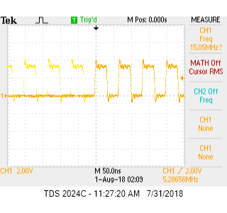
Jacob Hwang | Output Timing Drifting | Hello,
I have designed four DRS4 chips (36 channels) on my board running at 1GHz (REFCLK=488.28KHz) and ROI mode. All 4 chips' REFCLK, DWRITE, RSRLOAD, and SRCLK are buffer driven by the same source. SRCLK is set to 40MHz to reduce the readout time.
If I injected a sine waveform, buffered and splitted into all 36 channels,I noticed all 9 channels on each DRS4 chip output almost the same as expected. But the output phase from chip to chip is drifting as shown in attached picture which is from two different channels of different chips. From the few boards I have built, I found few chips are drifting more than the others and is different on every board.
The sympton look like the DRS4 internal PLL is drifting, but I checked the DTAP output on every chip and found it's dead-lock steady even I used persistance setting on my oscilloscope. Do you have any suggestion how to attack this problem? Thank you.
Jacob Hwang
|
|
538
|
Fri Sep 30 17:03:38 2016 |
Stefan Ritt | Output Timing Drifting | Hi Jacob,
you are missing the timing calibration. Each sampling cell has not the same width. Running at 5 GSPS, cell widths scatter from 150 ps to 250 ps. If you integrate these widhts, you get a time scale which can be off by a few ns between chips, something you see in your plot. Here is a paper which explains in detail how to do a timing calibration: https://arxiv.org/abs/1405.4975
Cheers,
Stefan
| Jacob Hwang wrote: |
|
Hello,
I have designed four DRS4 chips (36 channels) on my board running at 1GHz (REFCLK=488.28KHz) and ROI mode. All 4 chips' REFCLK, DWRITE, RSRLOAD, and SRCLK are buffer driven by the same source. SRCLK is set to 40MHz to reduce the readout time.
If I injected a sine waveform, buffered and splitted into all 36 channels,I noticed all 9 channels on each DRS4 chip output almost the same as expected. But the output phase from chip to chip is drifting as shown in attached picture which is from two different channels of different chips. From the few boards I have built, I found few chips are drifting more than the others and is different on every board.
The sympton look like the DRS4 internal PLL is drifting, but I checked the DTAP output on every chip and found it's dead-lock steady even I used persistance setting on my oscilloscope. Do you have any suggestion how to attack this problem? Thank you.
Jacob Hwang
|
|
|