| ID |
Date |
Author |
Subject |
|
568
|
Thu Nov 24 08:13:23 2016 |
Stefan Ritt | PLL did not lock | Which serial number has the board? Has it been in use before or is it a new board?
Stefan
| Alexey Lubinets wrote: |
|
Hello, everybody!
I installed DRSosc and DRScl. Command line works normally (at least, it can "see" the board). But when I start the oscilloscope, I have an error: "PLLs did not lock on USB board #0, serial number #...". In Info section I can see the board type = 9 (and in the error message I have "USB board #0").
After that I have a warning: "Board on USB0 has invalid voltge calibration. Only raw data will be displayed". I tried to execute voltage calibration using DRSosc and DRScl, but it did not help.
Did anybody face such broblems? Does anybody know, how to fix them?
Thank you. Alexey.
|
|
|
570
|
Mon Nov 28 16:48:15 2016 |
Alexey Lubinets | PLL did not lock | The serial number is 2586. This board is about two years old, and it might be in use (but I do not know exactly).
| Stefan Ritt wrote: |
|
Which serial number has the board? Has it been in use before or is it a new board?
Stefan
| Alexey Lubinets wrote: |
|
Hello, everybody!
I installed DRSosc and DRScl. Command line works normally (at least, it can "see" the board). But when I start the oscilloscope, I have an error: "PLLs did not lock on USB board #0, serial number #...". In Info section I can see the board type = 9 (and in the error message I have "USB board #0").
After that I have a warning: "Board on USB0 has invalid voltge calibration. Only raw data will be displayed". I tried to execute voltage calibration using DRSosc and DRScl, but it did not help.
Did anybody face such broblems? Does anybody know, how to fix them?
Thank you. Alexey.
|
|
|
|
571
|
Mon Nov 28 16:52:38 2016 |
Stefan Ritt | PLL did not lock | Have you tried to unplug and re-plug the board a few times? According to our database, you should have three boards. Do all three show the same behavior or only this board? In case all three show this, it could be a hint of a software problem. If two boards are good and one is bad, this would be a hint of a hardware problem (broken board).
Stefan
| Alexey Lubinets wrote: |
|
The serial number is 2586. This board is about two years old, and it might be in use (but I do not know exactly).
| Stefan Ritt wrote: |
|
Which serial number has the board? Has it been in use before or is it a new board?
Stefan
| Alexey Lubinets wrote: |
|
Hello, everybody!
I installed DRSosc and DRScl. Command line works normally (at least, it can "see" the board). But when I start the oscilloscope, I have an error: "PLLs did not lock on USB board #0, serial number #...". In Info section I can see the board type = 9 (and in the error message I have "USB board #0").
After that I have a warning: "Board on USB0 has invalid voltge calibration. Only raw data will be displayed". I tried to execute voltage calibration using DRSosc and DRScl, but it did not help.
Did anybody face such broblems? Does anybody know, how to fix them?
Thank you. Alexey.
|
|
|
|
|
57
|
Sun Mar 21 02:03:44 2010 |
Hao Huan | PLL Loop Filter Configuration | Hi Stefan,
in the datasheet it says at 6GSPS the typical loop filter parameters are 220Ω, 2.2nF and 27nF. If I want to run the Domino wave nominally at 1GHz, i.e. with a reference clock frequency around 0.5MHz, is there any recommended loop filter configuration? Is the setup of the evaluation board, that is, 220Ω, 3.3nF and 33nF an optimal choice?
Thank you very much.
|
|
58
|
Mon Mar 22 09:12:19 2010 |
Stefan Ritt | PLL Loop Filter Configuration |
| Hao Huan wrote: |
|
in the datasheet it says at 6GSPS the typical loop filter parameters are 220Ω, 2.2nF and 27nF. If I want to run the Domino wave nominally at 1GHz, i.e. with a reference clock frequency around 0.5MHz, is there any recommended loop filter configuration? Is the setup of the evaluation board, that is, 220Ω, 3.3nF and 33nF an optimal choice?
|
The setup of the evaluation board is a good compromise which runs between 1 GHz and 5 GHz. Unfortunately I never found the time to investigate this in more detail. So if someone is willing to measure settling time and phase jitter with various combinations of R, C1 and C2, I'm more than happy to include this into the datasheet. |
|
451
|
Wed Nov 25 02:52:35 2015 |
Chris Thompson | PC software beyond Windows 7 | I am new to this forum. I have ordered a DRS4 evaluation board for doing experiments with very fast PET detectors. It has not arrived yet. The version of the manual I downloaded today shows software installation instructions for Windows 7 and earlier versions. I intend to use it on a 64bit PC running Windows 8.1. Will the Windows 7 driver work, or is there an updated version for Windows 8 or 10? |
|
452
|
Wed Nov 25 08:20:47 2015 |
Stefan Ritt | PC software beyond Windows 7 | Have a look here elog:434
| Chris Thompson wrote: |
|
I am new to this forum. I have ordered a DRS4 evaluation board for doing experiments with very fast PET detectors. It has not arrived yet. The version of the manual I downloaded today shows software installation instructions for Windows 7 and earlier versions. I intend to use it on a 64bit PC running Windows 8.1. Will the Windows 7 driver work, or is there an updated version for Windows 8 or 10?
|
|
|
453
|
Wed Nov 25 17:36:25 2015 |
Chris Thompson | PC software beyond Windows 7 | I tried this suggestion of changing the startup settings to ingore driver license signing (as suggested in the post # 434), but when I tried to install the software I got a error message which I captured from the screen and I have attached. Perhaps I have the wrong version, or, as suggested, the file I downloaded from your site is incomplete?
| Stefan Ritt wrote: |
|
Have a look here elog:434
| Chris Thompson wrote: |
|
I am new to this forum. I have ordered a DRS4 evaluation board for doing experiments with very fast PET detectors. It has not arrived yet. The version of the manual I downloaded today shows software installation instructions for Windows 7 and earlier versions. I intend to use it on a 64bit PC running Windows 8.1. Will the Windows 7 driver work, or is there an updated version for Windows 8 or 10?
|
|
|
| Attachment 1: Installation_failure_screen.jpg
|

|
|
455
|
Sat Dec 5 02:39:20 2015 |
Chris Thompson | PC software beyond Windows 7 | I tried restarting Windows 10 in a way the allowed me to use "advanced startup options" Option 7 suggested it was to restart without mandatory driver signing. However, the error persists. Has anyone tested this latest version 5.0.4 on Windows 10? My hardware arrived today, and I am anxious to test it.!!!!
| Chris Thompson wrote: |
|
I tried this suggestion of changing the startup settings to ingore driver license signing (as suggested in the post # 434), but when I tried to install the software I got a error message which I captured from the screen and I have attached. Perhaps I have the wrong version, or, as suggested, the file I downloaded from your site is incomplete?
| Stefan Ritt wrote: |
|
Have a look here elog:434
| Chris Thompson wrote: |
|
I am new to this forum. I have ordered a DRS4 evaluation board for doing experiments with very fast PET detectors. It has not arrived yet. The version of the manual I downloaded today shows software installation instructions for Windows 7 and earlier versions. I intend to use it on a 64bit PC running Windows 8.1. Will the Windows 7 driver work, or is there an updated version for Windows 8 or 10?
|
|
|
|
|
456
|
Sat Dec 5 03:21:21 2015 |
Chris Thompson | PC software beyond Windows 7 | On a hunch, I tried downloading V 5.0.3 instead. This works, and I now have the oscilloscope mode displaying signals! (just to make sure, I re-tire version 5.0.4 and still get the same error. So, in summary V 5.0.3 seems to install successfully and work with Windows 10, but the newer V5.0.4 does not install... I assmume that I am missing something though, as the newer version is 10 Mbytes bigger!
| Chris Thompson wrote: |
|
I tried restarting Windows 10 in a way the allowed me to use "advanced startup options" Option 7 suggested it was to restart without mandatory driver signing. However, the error persists. Has anyone tested this latest version 5.0.4 on Windows 10? My hardware arrived today, and I am anxious to test it.!!!!
| Chris Thompson wrote: |
|
I tried this suggestion of changing the startup settings to ingore driver license signing (as suggested in the post # 434), but when I tried to install the software I got a error message which I captured from the screen and I have attached. Perhaps I have the wrong version, or, as suggested, the file I downloaded from your site is incomplete?
| Stefan Ritt wrote: |
|
Have a look here elog:434
| Chris Thompson wrote: |
|
I am new to this forum. I have ordered a DRS4 evaluation board for doing experiments with very fast PET detectors. It has not arrived yet. The version of the manual I downloaded today shows software installation instructions for Windows 7 and earlier versions. I intend to use it on a 64bit PC running Windows 8.1. Will the Windows 7 driver work, or is there an updated version for Windows 8 or 10?
|
|
|
|
|
|
468
|
Tue Jan 12 12:57:46 2016 |
Stefan Ritt | PC software beyond Windows 7 | The 5.0.4 version was corrupt on our server. I fixed it, so now it shoudl also work fine (although there are only very minor changes between 5.0.3 and 5.0.4).
/Stefan
| Chris Thompson wrote: |
|
On a hunch, I tried downloading V 5.0.3 instead. This works, and I now have the oscilloscope mode displaying signals! (just to make sure, I re-tire version 5.0.4 and still get the same error. So, in summary V 5.0.3 seems to install successfully and work with Windows 10, but the newer V5.0.4 does not install... I assmume that I am missing something though, as the newer version is 10 Mbytes bigger!
| Chris Thompson wrote: |
|
I tried restarting Windows 10 in a way the allowed me to use "advanced startup options" Option 7 suggested it was to restart without mandatory driver signing. However, the error persists. Has anyone tested this latest version 5.0.4 on Windows 10? My hardware arrived today, and I am anxious to test it.!!!!
| Chris Thompson wrote: |
|
I tried this suggestion of changing the startup settings to ingore driver license signing (as suggested in the post # 434), but when I tried to install the software I got a error message which I captured from the screen and I have attached. Perhaps I have the wrong version, or, as suggested, the file I downloaded from your site is incomplete?
| Stefan Ritt wrote: |
|
Have a look here elog:434
| Chris Thompson wrote: |
|
I am new to this forum. I have ordered a DRS4 evaluation board for doing experiments with very fast PET detectors. It has not arrived yet. The version of the manual I downloaded today shows software installation instructions for Windows 7 and earlier versions. I intend to use it on a 64bit PC running Windows 8.1. Will the Windows 7 driver work, or is there an updated version for Windows 8 or 10?
|
|
|
|
|
|
|
537
|
Thu Sep 29 17:26:13 2016 |
Jacob Hwang | Output Timing Drifting | Hello,
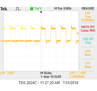
I have designed four DRS4 chips (36 channels) on my board running at 1GHz (REFCLK=488.28KHz) and ROI mode. All 4 chips' REFCLK, DWRITE, RSRLOAD, and SRCLK are buffer driven by the same source. SRCLK is set to 40MHz to reduce the readout time.
If I injected a sine waveform, buffered and splitted into all 36 channels,I noticed all 9 channels on each DRS4 chip output almost the same as expected. But the output phase from chip to chip is drifting as shown in attached picture which is from two different channels of different chips. From the few boards I have built, I found few chips are drifting more than the others and is different on every board.
The sympton look like the DRS4 internal PLL is drifting, but I checked the DTAP output on every chip and found it's dead-lock steady even I used persistance setting on my oscilloscope. Do you have any suggestion how to attack this problem? Thank you.
Jacob Hwang
|
| Attachment 1: Output_Drifting.jpg
|

|
|
538
|
Fri Sep 30 17:03:38 2016 |
Stefan Ritt | Output Timing Drifting | Hi Jacob,
you are missing the timing calibration. Each sampling cell has not the same width. Running at 5 GSPS, cell widths scatter from 150 ps to 250 ps. If you integrate these widhts, you get a time scale which can be off by a few ns between chips, something you see in your plot. Here is a paper which explains in detail how to do a timing calibration: https://arxiv.org/abs/1405.4975
Cheers,
Stefan
| Jacob Hwang wrote: |
|
Hello,
I have designed four DRS4 chips (36 channels) on my board running at 1GHz (REFCLK=488.28KHz) and ROI mode. All 4 chips' REFCLK, DWRITE, RSRLOAD, and SRCLK are buffer driven by the same source. SRCLK is set to 40MHz to reduce the readout time.
If I injected a sine waveform, buffered and splitted into all 36 channels,I noticed all 9 channels on each DRS4 chip output almost the same as expected. But the output phase from chip to chip is drifting as shown in attached picture which is from two different channels of different chips. From the few boards I have built, I found few chips are drifting more than the others and is different on every board.
The sympton look like the DRS4 internal PLL is drifting, but I checked the DTAP output on every chip and found it's dead-lock steady even I used persistance setting on my oscilloscope. Do you have any suggestion how to attack this problem? Thank you.
Jacob Hwang
|
|
|
710
|
Wed Aug 1 00:49:30 2018 |
Sean Quinn | Optimal readout speed | Dear DRS4 team,
On page 3 of the data sheet, Table 1. for readout speed a typical value of 10 MHz is specified, but in the comment column it notes optimal performance achieved at 33 MHz.
I see the V5.1 eval board runs at 16 MHz. I'd like to understand the rationale for this using speed, instead of 33 MHz. Is there an SNR issue for the ADC at the higher speed, even though this is optimal for the DRS4?
Very best,
Sean |
|
713
|
Tue Aug 21 14:36:44 2018 |
Stefan Ritt | Optimal readout speed | The analog output of the DRS4 chip needs some time to settle. In principle it need an infinite amout of time (exponential curve) to settle to 100% of the final value. So if we sample after a finite time, there is some error we do. Some of the error will be taken care of the voltage calibration, but there remains some residual error depending on the value of the previous sampling cell. So all sampling speeds 10 MHz, 16 MHz, 33 MHz are kind of rule of thumbs. In the end we run the evaluation board at 16 MHz to save a little bit of power (which is limited on an USB device). But I never made a careful study of noise-after-calibration vs. sampling speed. If you have some measurements, I'm happt to include it in the data sheet.
Stefan
| Sean Quinn wrote: |
|
Dear DRS4 team,
On page 3 of the data sheet, Table 1. for readout speed a typical value of 10 MHz is specified, but in the comment column it notes optimal performance achieved at 33 MHz.
I see the V5.1 eval board runs at 16 MHz. I'd like to understand the rationale for this using speed, instead of 33 MHz. Is there an SNR issue for the ADC at the higher speed, even though this is optimal for the DRS4?
Very best,
Sean
|
|
|
217
|
Wed Feb 13 16:58:40 2013 |
Martin Petriska | Nonuniform sampling | Are there any plans to include reconstruction of nonuniform sampling in DRS4 to get uniformly sampled data?
Im now reading article IEEE Trans on Circ. ans Systems I, Vol.55 No.8 sept. 2008 Reconstruction of Nonuniformly Sampled Bandlimited Signals Usinga Differentiator–Multiplier Cascade by Stefan Tertinek and Christian Vogel
and plan to implement it, but may be somebody has it done before me.
|
|
218
|
Wed Feb 13 17:03:53 2013 |
Stefan Ritt | Nonuniform sampling |
| Martin Petriska wrote: |
|
Are there any plans to include reconstruction of nonuniform sampling in DRS4 to get uniformly sampled data?
Im now reading article IEEE Trans on Circ. ans Systems I, Vol.55 No.8 sept. 2008 Reconstruction of Nonuniformly Sampled Bandlimited Signals Usinga Differentiator–Multiplier Cascade by Stefan Tertinek and Christian Vogel
and plan to implement it, but may be somebody has it done before me.
|
Interesting paper. I was not aware of this method. Sounds interesting. AFAIK, nobody has implemented it so far.
My (old) plan was to linearly interpolate samples (something you could do in an FPGA as well), but this will introduce (small) errors. The next best thing would be to do some spline interpolation, but this is time consuming and not suited for an FPGA.
If you get good results with the method above, please let others know about it.
/Stefan |
|
916
|
Thu Mar 27 15:53:10 2025 |
Justin Tabbett | Noisy counts with adapted drs_exam.cpp | Greetings,
I have adapted the drs_exam.cpp to allow for a user input number of channels and trigger levels.
The program mostly works well, however there are counts which form a noise peak, imposed on the regular channel response.
To illustrate, I acquired 10,000 counts (measuring peak to peak) with the drsosc, and with my adapted script, with two channels and OR trigger logic.
Is there something missing in my code that could explain the cause of this noise peak? I have attached the .cpp file.
Many thanks,
Justin |
| Attachment 1: Channel_1_2.png
|

|
| Attachment 2: drs_exam.cpp
|
/********************************************************************\

  Name:         drs_exam.cpp
  Created by:   Stefan Ritt

  Contents:     Simple example application to read out a DRS4
                evaluation board

  $Id: drs_exam.cpp 21308 2014-04-11 14:50:16Z ritt $

\********************************************************************/

#include <math.h>

#ifdef _MSC_VER

#include <windows.h>

#elif defined(OS_LINUX)

#define O_BINARY 0

#include <unistd.h>
#include <ctype.h>
#include <sys/ioctl.h>
#include <errno.h>

#define DIR_SEPARATOR '/'

#endif

#include <stdio.h>
#include <string.h>
#include <stdlib.h>

#include "strlcpy.h"
#include "DRS.h"

#include <math.h>

#include <cstdio>

#include <fcntl.h>
#include <time.h>
#include <sys/stat.h>
#include <assert.h>
#include <iostream>
#include <chrono>
#include <vector>
#include <algorithm>
#include <iostream>
#include <conio.h>  // For _kbhit() and _getch() functions (Windows only)

/*------------------------------------------------------------------*/

int main()
{
    int i, j, k, l, m, n, p, numC, nBoards, i_start, i_end, csel;
    char str[256], param[10][100];
    DRS* drs;
    DRSBoard* b;
    float time_array[8][1024];
    float wave_array[8][1024];
    FILE* f;
    FILE* fph;

    /* do initial scan */
    drs = new DRS();

    /* show any found board(s) */
    for (i = 0; i < drs->GetNumberOfBoards(); i++) {
        b = drs->GetBoard(i);
        printf("Found DRS4 evaluation board, serial #%d, firmware revision %d\n",
            b->GetBoardSerialNumber(), b->GetFirmwareVersion());
    }

    /* exit if no board found */
    nBoards = drs->GetNumberOfBoards();
    if (nBoards == 0) {
        printf("No DRS4 evaluation board found\n");
        return 0;
    }

    /* continue working with first board only */
    b = drs->GetBoard(0);

    /* initialize board */
    b->Init();

    /* set sampling frequency */
    b->SetFrequency(5, true);

    /* enable transparent mode needed for analog trigger */
    b->SetTranspMode(1);

    /* set input range to -0.5V ... +0.5V */
    b->SetInputRange(0);

    /* use following line to turn on the internal 100 MHz clock connected to all channels  */
    b->EnableTcal(1);

    printf("Number of channels: ");
    fgets(str, sizeof(str), stdin);
    csel = atoi(str); //Number of channels
    printf("DRS4 configured for %d channels\n", atoi(str));

    b->EnableTrigger(1, 0);
    b->SetTriggerSource(15); // 15 is an OR on CH1-4, 3 is OR on CH1-2, apparently 768 is the AND value for CH1 and CH2
    b->SetTriggerPolarity(true);        // positive edge -> false, negative edge -> true

    std::vector<int> avn = { 1, 2, 3, 4 };  // Available number of channels: 0, 2, 4, 6
    std::vector<double> triglist = { 0, 0, 0, 0 }; //Store trigger thresholds
    for (i = 0;i < csel;i++) {
        printf("Channel %d trigger level (V): ", avn[i]);
        fgets(str, sizeof(str), stdin);
        b->SetIndividualTriggerLevel((avn[i] - 1), atof(str));
        triglist[i] = atof(str) * -1000; //store as mV
        printf("Trigger level set to %1.3lf Volt\n", atof(str));
    }
    b->SetTriggerDelayNs(0);             // zero ns trigger delay

    fph = fopen("fph.txt", "w");
    if (fph == NULL) {
        perror("ERROR: Cannot open file \"fph.txt\"");
        return 1;
    }

    numC = 0; //Event counter

    for (i = 0;i < csel;i++) {
        fprintf(fph, "%7.1f,", triglist[i]);
    }

    fprintf(fph, "%d\n", 0);
    printf("hi\n");
    while (true) {
        // Check if a key is pressed
        if (_kbhit()) {
            char ch = _getch();  // Read the pressed key without waiting for Enter
            if (ch == 'q')       // If 'q' is pressed, exit the loop
                break;
        }

        k = 0;
        l = 0;
        m = 0;
        n = 0;

        std::vector<double> outh(csel, 0); //Create output for pulse heights as 0s
        printf("Before startdomino\n");
        b->StartDomino();

        /* wait for trigger */
        printf("Before fflushstdout\n");
        fflush(stdout);
        while (b->IsBusy());

        /*Take time stamp*/

        auto now = std::chrono::system_clock::now();
        auto duration = std::chrono::duration<double>(now.time_since_epoch());
        double timeT = duration.count();

        /*Read waveforms*/

        b->TransferWaves(0, 8);

        for (p = 0;p < csel;p++) {
            b->GetWave(0, p * 2, wave_array[p]); // this reads channel i*2 to array index i
            float minVali = wave_array[p][0], maxVali = wave_array[p][0]; //creates floats for min and max values
            for (i = 0; i < 1024; i++) {
                // find the min and max values from each channel
                if (wave_array[p][i] < minVali) minVali = wave_array[p][i];
                if (wave_array[p][i] > maxVali) maxVali = wave_array[p][i];
            }
            float heighti = maxVali - minVali;
            outh[p] = heighti;
        }

        for (double value : outh) {
            fprintf(fph, "%7.1f,", value);
        }

        fprintf(fph, "%.6f\n", timeT);
        printf("%d\n", numC);


        if (numC % 1000 == 0) {
            fflush(fph);
        }
        numC++;


    }

    fclose(fph);
    std::getchar();

    /* delete DRS object -> close USB connection */
    delete drs;
}
|
|
519
|
Thu Apr 28 15:47:53 2016 |
Stefan Ritt | New software version and binary format | A new software version 5.0.5 has been released today. This fixes a few bugs in multi-board configurations, and adds saving of the scaler values into XML and binary files. Please note that the binary file format has been changed for that. The new format is described in an updated manual (page 25), and reflected in a new read_binary.cpp program contained in the distribution.
/Stefan |
|
531
|
Wed Jun 29 09:10:01 2016 |
Stefan Ritt | Negative input signals | Hello everybody,
I get often asked if the DRS4 evaluation board can accomodate negative input pulses going to -1V. This is unfortunately not possible, since the board is mainly for evaluation of the DRS4 chip and should not be seen as a complete oscilloscope with flexible input stage. So the maximum it can do is -0.5V to +0.5V or 0V to 1V. For -1V signals, one can use however a passive inverter like this one:
http://www.phillipsscientific.com/pdf/460ds.pdf
And for signals going furhter (-2V, -10V) one can use a passive attenuator like this one:
http://www.pomonaelectronics.com/pdf/d4108_K5513_101.pdf
Best regards,
Stefan
|
|