 Thu Feb 21 09:51:24 2019, Lev Pavlov, no board found Thu Feb 21 09:51:24 2019, Lev Pavlov, no board found
|
Hey. Yes, the program is running as administrator. By the way, this is win10. Your drs_exam works fine. My drs_exam compiled wrote no board found. Maybe this is a problem like in the post https://elog.psi.ch/elogs/DRS4+Forum/698. Maybe there were solutions to the problems?
Thank You
Lev
| Stefan Ritt wrote: |
|
No idea. Maye some access problem. Have you tried to start your program under an admin account?
Stefan
| Lev Pavlov wrote: |
|
Great, drs_exam compiles without problems. Now when you run the compiled file drs_exam writes board not found, but drsosc and drscl work without problems. What could possibly be the matter?
thanks for your patience
Lev
| Stefan Ritt wrote: |
|
You have to change the path to libusb-1.0.lib to the one where you installed it.
Stefan
| Lev Pavlov wrote: |
|
Hey. Strange problem. Why does the compiler refer there at all? Library installed drsosc works
LINK : fatal error LNK1104: cannot open file "C:\meg\online\drivers\drs\libusb-1.0\libusb-1.0.lib"
|
|
|
|
|
|
Thu Feb 21 09:57:53 2019, Stefan Ritt, no board found
|
Could be. Have you tried that elog:657
Stefan
| Lev Pavlov wrote: |
|
Hey. Yes, the program is running as administrator. By the way, this is win10. Your drs_exam works fine. My drs_exam compiled wrote no board found. Maybe this is a problem like in the post https://elog.psi.ch/elogs/DRS4+Forum/698. Maybe there were solutions to the problems?
Thank You
Lev
| Stefan Ritt wrote: |
|
No idea. Maye some access problem. Have you tried to start your program under an admin account?
Stefan
| Lev Pavlov wrote: |
|
Great, drs_exam compiles without problems. Now when you run the compiled file drs_exam writes board not found, but drsosc and drscl work without problems. What could possibly be the matter?
thanks for your patience
Lev
| Stefan Ritt wrote: |
|
You have to change the path to libusb-1.0.lib to the one where you installed it.
Stefan
| Lev Pavlov wrote: |
|
Hey. Strange problem. Why does the compiler refer there at all? Library installed drsosc works
LINK : fatal error LNK1104: cannot open file "C:\meg\online\drivers\drs\libusb-1.0\libusb-1.0.lib"
|
|
|
|
|
|
|
Mon Feb 25 08:40:44 2019, Lev Pavlov, no board found
|
Hello. When compiling drs_exam, do you need to use a "static "version of usblib or a "dynamic" version?"The problem with "no board found" is not solved. Thanks for your help.
Lev.
| Stefan Ritt wrote: |
|
Could be. Have you tried that elog:657
Stefan
| Lev Pavlov wrote: |
|
Hey. Yes, the program is running as administrator. By the way, this is win10. Your drs_exam works fine. My drs_exam compiled wrote no board found. Maybe this is a problem like in the post https://elog.psi.ch/elogs/DRS4+Forum/698. Maybe there were solutions to the problems?
Thank You
Lev
| Stefan Ritt wrote: |
|
No idea. Maye some access problem. Have you tried to start your program under an admin account?
Stefan
| Lev Pavlov wrote: |
|
Great, drs_exam compiles without problems. Now when you run the compiled file drs_exam writes board not found, but drsosc and drscl work without problems. What could possibly be the matter?
thanks for your patience
Lev
| Stefan Ritt wrote: |
|
You have to change the path to libusb-1.0.lib to the one where you installed it.
Stefan
| Lev Pavlov wrote: |
|
Hey. Strange problem. Why does the compiler refer there at all? Library installed drsosc works
LINK : fatal error LNK1104: cannot open file "C:\meg\online\drivers\drs\libusb-1.0\libusb-1.0.lib"
|
|
|
|
|
|
|
|
Mon Feb 25 08:48:27 2019, Stefan Ritt, no board found
|
"dynamic" or "static" does not matter, as long as you don't use your program on another computer. I have no more idea about the "no board found" problem. It works ok on all computers I tried at our lab.
Stefan
| Lev Pavlov wrote: |
|
Hello. When compiling drs_exam, do you need to use a "static "version of usblib or a "dynamic" version?"The problem with "no board found" is not solved. Thanks for your help.
Lev
|
|
Tue Jul 28 22:40:44 2020, Razvan Stefan Gornea, no board found 
|
I have a very similar problem, the command line doesn't work but the oscilloscope program does! Tried to fix it using Zadig driver update. Using Windows 7....
DRS command line tool, Revision 21435
Type 'help' for a list of available commands.
USB successfully scanned, but no boards found
No DRS Boards found
For completion, I just tested that the test program gives the same error message
C:\Program Files (x86)\DRS\bin>.\drs_exam.exe
USB successfully scanned, but no boards found
No DRS4 evaluation board found
| Stefan Ritt wrote: |
|
"dynamic" or "static" does not matter, as long as you don't use your program on another computer. I have no more idea about the "no board found" problem. It works ok on all computers I tried at our lab.
Stefan
| Lev Pavlov wrote: |
|
Hello. When compiling drs_exam, do you need to use a "static "version of usblib or a "dynamic" version?"The problem with "no board found" is not solved. Thanks for your help.
Lev
|
|
|
 Wed Dec 30 14:28:33 2009, aliyilmaz, normal_mode_in_drs_exam.cpp Wed Dec 30 14:28:33 2009, aliyilmaz, normal_mode_in_drs_exam.cpp
|
Dear Mr. S. Ritt
i am Ms. student , am working with your DRS4 board to calculate the time of flight of the cosmic particle which passes trough the hodoscope . i see the signals at scope , which is negative (i don't want to take positive side of the signal).
i am using your drs_exap.cpp file to take the data, i set the analog trigger source , threshold level is negative, like this(b->SetTriggerLevel(-30, true) ); but the exam file also registers the positive side of signal (i think that is spike or internal reflection), is it possible to eliminate this spike? Also i want to register the data just after the threshold value, but that is always triggered, i think that caused from the mode. Is it possible to set the trigger mode to normal in exam file?,and how can i do that?
Best regards.
Sincerely,
Ali YILMAZ (ali.yilmaz@roma1.infn.it)
|
|
Mon Jan 11 16:32:21 2010, Stefan Ritt, normal_mode_in_drs_exam.cpp
|
| aliyilmaz wrote: |
|
Dear Mr. S. Ritt
i am Ms. student , am working with your DRS4 board to calculate the time of flight of the cosmic particle which passes trough the hodoscope . i see the signals at scope , which is negative (i don't want to take positive side of the signal).
i am using your drs_exap.cpp file to take the data, i set the analog trigger source , threshold level is negative, like this(b->SetTriggerLevel(-30, true) ); but the exam file also registers the positive side of signal (i think that is spike or internal reflection), is it possible to eliminate this spike? Also i want to register the data just after the threshold value, but that is always triggered, i think that caused from the mode. Is it possible to set the trigger mode to normal in exam file?,and how can i do that?
Best regards.
Sincerely,
Ali YILMAZ (ali.yilmaz@roma1.infn.it)
|
Please note that SetTriggerLevel(level, polarity) needs "level" in volts, not millivolts, so you need SetTriggerLevel(-0.3, true). The trigger mode is not specified with any library call, but depends on what your program does. If you always poll on IsBusy(), then you are already in "normal" mode. The auto mode can only be achieved on the user application level by doing an "artifical" trigger by calling SoftTrigger() if there are no hardware triggers for a certain time. |
|
Fri Oct 30 03:31:54 2009, Jinhong Wang, outline dimension of DRS4
|
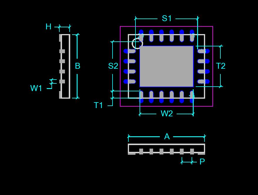
Fig.1 typical dimension of QFN package
Above is the typical dimension specification for QFN package. I cann't find the corresponding "T1" as in Fig.1 in the DRS4 documents, nor any of the tolerance of the dimensions, which are usually expressed in the form of a range between a min. value and a max. value.
So will you specify the dimension of "T1" and "W1", and the dimension tolerance of them?
Thanks and best wishes!
Jinhong Wang University of Science and Technology of China |
|
Wed Nov 4 14:42:22 2009, Stefan Ritt, outline dimension of DRS4
|
| Jinhong Wang wrote: |
|
Fig.1 typical dimension of QFN package
Above is the typical dimension specification for QFN package. I cann't find the corresponding "T1" as in Fig.1 in the DRS4 documents, nor any of the tolerance of the dimensions, which are usually expressed in the form of a range between a min. value and a max. value.
So will you specify the dimension of "T1" and "W1", and the dimension tolerance of them?
Thanks and best wishes!
Jinhong Wang University of Science and Technology of China
|
Please find attached the complete dimensions. |
|
Mon Oct 19 11:26:29 2009, Jinhong Wang, output common mode voltage of DRS4
|
Hello Mr. Stifan.Ritt
In the DSR4 datasheet, it is mentioned that there is an additional buffer at each analog output, this buffer shifts the the differential range of -0.5V~0.5V to 0.8V~1.8V. Does it mean that this buffer shifts a voltage of about 1.3V for the primary differential range?
Again for the differential range of -0.5V~0.5V, can the common mode voltage of the analog output at OUT+/OUT- be chaned? In the example presented in the datasheet, OUT+ is 0.8V~1.8V and OUT- is 1.8V~0.8V. So for an output swing of 2V p-p, can the common mode voltage be modified to the desired value? Supposed that the input ranges from -0.5V~0.5V.
Thank you!
Jinhong Wang |
|
Mon Oct 19 12:46:12 2009, Stefan Ritt, output common mode voltage of DRS4
|
| Jinhong Wang wrote: |
|
Does it mean that this buffer shifts a voltage of about 1.3V for the primary differential range?
|
No. It shifts about ROFS-0.25V. So only if ROFS=1.55V, the shift will be 1.3V.
| Jinhong Wang wrote: |
|
Again for the differential range of -0.5V~0.5V, can the common mode voltage of the analog output at OUT+/OUT- be chaned?
|
Just read the datasheet under "ANALOG OUTPUTS". I'm sorry if I did not describe this clearly, but the U+ voltage is fixed (only dependent on ROFS), and U- can be calculated using Uofs as written in the datasheet.
| Jinhong Wang wrote: |
|
In the example presented in the datasheet, OUT+ is 0.8V~1.8V and OUT- is 1.8V~0.8V. So for an output swing of 2V p-p, can the common mode voltage be modified to the desired value? Supposed that the input ranges from -0.5V~0.5V.
|
OUT+ is 0.8V~1.8V, OUT- is 2*Uofs-OUT+. So you can only change the OUT- level, not the OUT+ level. |
|
Thu Jan 25 05:24:05 2018, chen wenjun, problem with the drscl(drs507)
|
Hi! Stefan:
when I change a new computer(win7,64bit),I meet a problem that the drscl app cannot found the board! It shows"USB successfully scanned,but no boards found",but the drsosc runs well . when I connect to other win7*64bits computer,only one of them runs property! Is there any driver else I need to install?
Thank you!
Chen |
|
Thu Jan 25 08:00:16 2018, Stefan Ritt, problem with the drscl(drs507)
|
This problem has been reported by several people, like elog:551
So far I could not solve it. On the computers at our lab it works find so I cannot reproduce and fix the problem. One suspicion I have is that the underlying libusb library needs to be updated. You can try to install the newest version from their website at http://libusb.info/, but I haven't tried it myself.
Stefan
| chen wenjun wrote: |
|
Hi! Stefan:
when I change a new computer(win7,64bit),I meet a problem that the drscl app cannot found the board! It shows"USB successfully scanned,but no boards found",but the drsosc runs well . when I connect to other win7*64bits computer,only one of them runs property! Is there any driver else I need to install?
Thank you!
Chen
|
|
|
Thu Jan 25 08:07:32 2018, chen wenjun, problem with the drscl(drs507)
|
I have tried about 4 computers,only one worked fine.I truly want to know how others get this fixed,can you get in touch with them?
| Stefan Ritt wrote: |
|
This problem has been reported by several people, like elog:551
So far I could not solve it. On the computers at our lab it works find so I cannot reproduce and fix the problem. One suspicion I have is that the underlying libusb library needs to be updated. You can try to install the newest version from their website at http://libusb.info/, but I haven't tried it myself.
Stefan
| chen wenjun wrote: |
|
Hi! Stefan:
when I change a new computer(win7,64bit),I meet a problem that the drscl app cannot found the board! It shows"USB successfully scanned,but no boards found",but the drsosc runs well . when I connect to other win7*64bits computer,only one of them runs property! Is there any driver else I need to install?
Thank you!
Chen
|
|
|
|
Sun Jun 12 08:45:52 2016, Michael, problems of DRS4
|
Hi
I want to use DRS4 to digitize 16 channels of signals. The width of signal is about 20 ns, with frequency of 50Hz. The time differences between these 16 signals are not constant, arranging from 3us to 0. I am confused about this in some aspects.
- Can I use SIMULTANEOUS WRITINT AND READING to realize this? I saw the VHDL program, and if I understand it correctly, it did not work at this state.
- Or sampling at 1GSPS, using CASCADING OF CHANNELS, I can sample signal at most 4us or 8us, then digitizing all signals of one chip. Have you tested 4 or more channels cascading before?
Besides, any advice will be helpful!
Thank you. |
|
Sun Jun 12 08:49:54 2016, Michael, problems of DRS4
|
Hi
I want to use DRS4 to digitize 16 channels of signals. The width of signal is about 20 ns, with frequency of 50Hz. The time differences between these 16 signals are not constant, arranging from 3us to 0. I am confused about this in some aspects.
- Can I use SIMULTANEOUS WRITINT AND READING to realize this? I saw the VHDL program, and if I understand it correctly, it did not work at this state.
- Or sampling at 1GSPS, using CASCADING OF CHANNELS, I can sample signal at most 4us or 8us, then digitizing all signals of one chip. Have you tested 4 or more channels cascading before?
Besides, any advice will be helpful!
Thank you. |
|
Wed Jun 15 14:49:00 2016, Stefan Ritt, problems of DRS4
|
1. Simultaneous writing and reading is not possible with the DRS4 chip. The manual says differently on p. 14, but due to a bug in the chip waveforms get clipped at the end if one does that. We hopt to fix this problem in a future version of the chip.
2. You can cascade 2,4 or 8 channels. If you cascade 8 channels and run at 1 GSPS, you digitize a window of 8 us. If you have 16 signals, you then need 16 chips.
/Stefan
| Michael wrote: |
|
Hi
I want to use DRS4 to digitize 16 channels of signals. The width of signal is about 20 ns, with frequency of 50Hz. The time differences between these 16 signals are not constant, arranging from 3us to 0. I am confused about this in some aspects.
- Can I use SIMULTANEOUS WRITINT AND READING to realize this? I saw the VHDL program, and if I understand it correctly, it did not work at this state.
- Or sampling at 1GSPS, using CASCADING OF CHANNELS, I can sample signal at most 4us or 8us, then digitizing all signals of one chip. Have you tested 4 or more channels cascading before?
Besides, any advice will be helpful!
Thank you.
|
|
|
Wed Jun 1 22:29:01 2016, Dominik Neise, problems when stop cell >= 767 ??
|
Hello Stefan,
some colleages told me a story, I was neither able to confirm nor find anything in the datsheet about. According to them:
For some internal reason of the DRS4, if the “stop capacitor” of the DRS4 is >= 767, the true stop channel is one before the stop channel read from the DRS4. In other words, the stop channel which returns the DRS4 shifts after sampling to the capacitor ID 766.
Can you confirm that, or even say a few words about that matter?
I wanted to confirm this by plotting the stop cell distribution for random triggered data, taken with one of the FACT boards. I assumed (possibly misunderstanding the matter), that this would lead to missing values in the area of stop cell 767, but cannot see any significant excess or lack of entries in that area.
|
|
Wed Jun 1 23:16:01 2016, Stefan Ritt, problems when stop cell >= 767 ??
|
I cannot confirm the story with the "stop capacitor > 767". It can be seen from your plots that the distribution of stop cells are even, no holes or bins with double height.
There is an issue with cell 767, but this is when one tries to do simultaneous reading/writing to the chip. This does not really work as writen in the data sheet. Waveforms sometimgs get cut off at cell 767. But the stop cell is always correct, otherwise one could not calibrate the data. If you use the evaluation board for example, which is perfectly calibrated, and introduce an "artifical" shift like
if stop cell > 767 then
stop cell = stop cell + 1
then you would see that the voltage calibration would become wrong and very noisy.
Stefan
| Dominik Neise wrote: |
|
Hello Stefan,
some colleages told me a story, I was neither able to confirm nor find anything in the datsheet about. According to them:
For some internal reason of the DRS4, if the “stop capacitor” of the DRS4 is >= 767, the true stop channel is one before the stop channel read from the DRS4. In other words, the stop channel which returns the DRS4 shifts after sampling to the capacitor ID 766.
Can you confirm that, or even say a few words about that matter?
I wanted to confirm this by plotting the stop cell distribution for random triggered data, taken with one of the FACT boards. I assumed (possibly misunderstanding the matter), that this would lead to missing values in the area of stop cell 767, but cannot see any significant excess or lack of entries in that area.
|
|
|
Tue May 4 21:18:28 2021, Abaz Kryemadhi, recording only timestamp and amplitude and/or filesize maximum
|
Hi,
I have been collecting some date using the DRS4 board at a trigger rate of 10-20 Hz, I only need the timestamp and the amplitude, is there anyway to select only these two live as the data comes in to be stored.
Alternatively, What's the maximum file size or maximum number of events I can store in one binary file in linux.
Thanks,
Best,
Abaz |
|