 Wed Aug 13 20:17:19 2014, Roman Gredig, binary files time calibration header in drs-5.0.2 Wed Aug 13 20:17:19 2014, Roman Gredig, binary files time calibration header in drs-5.0.2
|
Dear Stefan

I have a problem considering binary data files.
Usually binary files start with TIME... (the time calibration header). But I observed the following reproducible problem.
1. Start to save a binary file (e.g. 001.dat) with 1000000 events.
2. Hit the close button before this limit has reached. (so far the binary files seems to be ok)
3. Start to save again a file with the SAME filename (and agree to replace the already existing it)
If I do it like this, the file has no time information anymore and starts directly with EHDR.

could it be that the m_evSerial counter is not reset in this specific situation?

Cheers,
Roman |
 Thu Oct 16 16:16:12 2014, Stefan Ritt, binary files time calibration header in drs-5.0.2 Thu Oct 16 16:16:12 2014, Stefan Ritt, binary files time calibration header in drs-5.0.2
|
> Dear Stefan
>
> I have a problem considering binary data files.
> Usually binary files start with TIME... (the time calibration header). But I observed the following reproducible problem.
> 1. Start to save a binary file (e.g. 001.dat) with 1000000 events.
> 2. Hit the close button before this limit has reached. (so far the binary files seems to be ok)
> 3. Start to save again a file with the SAME filename (and agree to replace the already existing it)
> If I do it like this, the file has no time information anymore and starts directly with EHDR.
>
> could it be that the m_evSerial counter is not reset in this specific situation?
>
> Cheers,
> Roman

This problem has also been fixed in version 5.0.3

/Stefan |
|
Tue Aug 26 14:16:26 2014, Roman Gredig, binary files with more than 4 drs board ver. 5.0.2
|
Dear Stefan

after having some problems with writing binary files with more than 4 drs boards (in multiboard-mode) I might
have found the solution.
In the file src/Osci.cpp at line 838 is:
unsigned char buffer[100000];

If I understand the binary format right, this works only with up to four boards. With the maximum number of
boards in your specification (16 boards) and all channels switched on on all boards this array needs to have
about 400000 entries (for the first event, where the time information is written too).

Could you please cross-check that?

Thank you very much!
Cheers,
Roman |
|
Thu Oct 16 16:15:16 2014, Stefan Ritt, binary files with more than 4 drs board ver. 5.0.2
|
> Dear Stefan
>
> after having some problems with writing binary files with more than 4 drs boards (in multiboard-mode) I might
> have found the solution.
> In the file src/Osci.cpp at line 838 is:
> unsigned char buffer[100000];
>
> If I understand the binary format right, this works only with up to four boards. With the maximum number of
> boards in your specification (16 boards) and all channels switched on on all boards this array needs to have
> about 400000 entries (for the first event, where the time information is written too).
>
> Could you please cross-check that?
>
> Thank you very much!
> Cheers,
> Roman

This problem has been fixed in software version 5.0.3

/Stefan |
|
Tue Oct 7 14:09:02 2014, Stephane Debieux, USB Microcontroller firmware
|
Hi,
I'm trying to recompile the USB microcontroller firmware starting from the drs_eval.c file but I'm not able to get a .iic file close to the one provided with the eval board. It seems to me that this drs_eval.iic file does not match the drs_eval.c and drs_eval.hex files or that I'm doing something wrong. Could you please help or give me an explanation.
Thank you.
Stephane
|
|
Mon Oct 13 16:46:56 2014, Stefan Ritt, USB Microcontroller firmware
|
| Stephane Debieux wrote: |
|
Hi,
I'm trying to recompile the USB microcontroller firmware starting from the drs_eval.c file but I'm not able to get a .iic file close to the one provided with the eval board. It seems to me that this drs_eval.iic file does not match the drs_eval.c and drs_eval.hex files or that I'm doing something wrong. Could you please help or give me an explanation.
Thank you.
Stephane
|
I did not touch the firmware since a couple of years, but I can confirm that the drs_eval.iic is the correct firmware file, since we use this one on all of our boards. To program it, you need the Cypress USB Console. You remove the jumper (to detach the EEPROM), then power the board (which then boots from the internal memory), connect to the board via the Cypress console, the put back the jumper while the board is running, then program the file into the EEPROM.
Best,
Stefan |
|
Mon Oct 13 17:08:40 2014, Stephane Debieux, USB Microcontroller firmware
|
| Stefan Ritt wrote: |
|
| Stephane Debieux wrote: |
|
Hi,
I'm trying to recompile the USB microcontroller firmware starting from the drs_eval.c file but I'm not able to get a .iic file close to the one provided with the eval board. It seems to me that this drs_eval.iic file does not match the drs_eval.c and drs_eval.hex files or that I'm doing something wrong. Could you please help or give me an explanation.
Thank you.
Stephane
|
I did not touch the firmware since a couple of years, but I can confirm that the drs_eval.iic is the correct firmware file, since we use this one on all of our boards. To program it, you need the Cypress USB Console. You remove the jumper (to detach the EEPROM), then power the board (which then boots from the internal memory), connect to the board via the Cypress console, the put back the jumper while the board is running, then program the file into the EEPROM.
Best,
Stefan
|
Thank you Stefan.
Would that be possible to get the corresponding drs_eval.c source file since I'm assuming the one provided with the eval board is not the right one?
Thank you.
Stephane |
|
Mon Oct 13 17:14:58 2014, Stefan Ritt, USB Microcontroller firmware
|
| Stephane Debieux wrote: |
|
| Stefan Ritt wrote: |
|
| Stephane Debieux wrote: |
|
Hi,
I'm trying to recompile the USB microcontroller firmware starting from the drs_eval.c file but I'm not able to get a .iic file close to the one provided with the eval board. It seems to me that this drs_eval.iic file does not match the drs_eval.c and drs_eval.hex files or that I'm doing something wrong. Could you please help or give me an explanation.
Thank you.
Stephane
|
I did not touch the firmware since a couple of years, but I can confirm that the drs_eval.iic is the correct firmware file, since we use this one on all of our boards. To program it, you need the Cypress USB Console. You remove the jumper (to detach the EEPROM), then power the board (which then boots from the internal memory), connect to the board via the Cypress console, the put back the jumper while the board is running, then program the file into the EEPROM.
Best,
Stefan
|
Thank you Stefan.
Would that be possible to get the corresponding drs_eval.c source file since I'm assuming the one provided with the eval board is not the right one?
Thank you.
Stephane
|
There is only one drs_eval.c version around, and I confirm that it is the one in the distribution. If you use different compiler settings, like optimisations, you might get a different executable file (and thus a .iic file), but the files have the same functionality.
Stefan |
|
Tue Oct 14 16:21:07 2014, Stephane Debieux, USB Microcontroller firmware
|
| Stefan Ritt wrote: |
|
| Stephane Debieux wrote: |
|
| Stefan Ritt wrote: |
|
| Stephane Debieux wrote: |
|
Hi,
I'm trying to recompile the USB microcontroller firmware starting from the drs_eval.c file but I'm not able to get a .iic file close to the one provided with the eval board. It seems to me that this drs_eval.iic file does not match the drs_eval.c and drs_eval.hex files or that I'm doing something wrong. Could you please help or give me an explanation.
Thank you.
Stephane
|
I did not touch the firmware since a couple of years, but I can confirm that the drs_eval.iic is the correct firmware file, since we use this one on all of our boards. To program it, you need the Cypress USB Console. You remove the jumper (to detach the EEPROM), then power the board (which then boots from the internal memory), connect to the board via the Cypress console, the put back the jumper while the board is running, then program the file into the EEPROM.
Best,
Stefan
|
Thank you Stefan.
Would that be possible to get the corresponding drs_eval.c source file since I'm assuming the one provided with the eval board is not the right one?
Thank you.
Stephane
|
There is only one drs_eval.c version around, and I confirm that it is the one in the distribution. If you use different compiler settings, like optimisations, you might get a different executable file (and thus a .iic file), but the files have the same functionality.
Stefan
|
I'm very sorry to insist but if I take the .hex of the distribution, convert it to .iic using the hex2bix utility, and reprogram the board, I can't read the board correctly (invalid magic number read with drscl for instance). Also, when using the uVision2 project file you provide and compiling the drs_eval.c, I get the same result (i.e. no way to generate a functional .iic file starting from the sources). So, either I'm doing something wrong (and I don't know what) or the drs_eval.c is not the correct one. |
|
Tue Oct 14 16:29:12 2014, Stefan Ritt, USB Microcontroller firmware
|
| Stephane Debieux wrote: |
|
| Stefan Ritt wrote: |
|
| Stephane Debieux wrote: |
|
| Stefan Ritt wrote: |
|
| Stephane Debieux wrote: |
|
Hi,
I'm trying to recompile the USB microcontroller firmware starting from the drs_eval.c file but I'm not able to get a .iic file close to the one provided with the eval board. It seems to me that this drs_eval.iic file does not match the drs_eval.c and drs_eval.hex files or that I'm doing something wrong. Could you please help or give me an explanation.
Thank you.
Stephane
|
I did not touch the firmware since a couple of years, but I can confirm that the drs_eval.iic is the correct firmware file, since we use this one on all of our boards. To program it, you need the Cypress USB Console. You remove the jumper (to detach the EEPROM), then power the board (which then boots from the internal memory), connect to the board via the Cypress console, the put back the jumper while the board is running, then program the file into the EEPROM.
Best,
Stefan
|
Thank you Stefan.
Would that be possible to get the corresponding drs_eval.c source file since I'm assuming the one provided with the eval board is not the right one?
Thank you.
Stephane
|
There is only one drs_eval.c version around, and I confirm that it is the one in the distribution. If you use different compiler settings, like optimisations, you might get a different executable file (and thus a .iic file), but the files have the same functionality.
Stefan
|
I'm very sorry to insist but if I take the .hex of the distribution, convert it to .iic using the hex2bix utility, and reprogram the board, I can't read the board correctly (invalid magic number read with drscl for instance). Also, when using the uVision2 project file you provide and compiling the drs_eval.c, I get the same result (i.e. no way to generate a functional .iic file starting from the sources). So, either I'm doing something wrong (and I don't know what) or the drs_eval.c is not the correct one.
|
And what happens if you program the .iic file from the distribution? |
|
Tue Oct 14 16:34:45 2014, Stephane Debieux, USB Microcontroller firmware
|
| Stefan Ritt wrote: |
|
| Stephane Debieux wrote: |
|
| Stefan Ritt wrote: |
|
| Stephane Debieux wrote: |
|
| Stefan Ritt wrote: |
|
| Stephane Debieux wrote: |
|
Hi,
I'm trying to recompile the USB microcontroller firmware starting from the drs_eval.c file but I'm not able to get a .iic file close to the one provided with the eval board. It seems to me that this drs_eval.iic file does not match the drs_eval.c and drs_eval.hex files or that I'm doing something wrong. Could you please help or give me an explanation.
Thank you.
Stephane
|
I did not touch the firmware since a couple of years, but I can confirm that the drs_eval.iic is the correct firmware file, since we use this one on all of our boards. To program it, you need the Cypress USB Console. You remove the jumper (to detach the EEPROM), then power the board (which then boots from the internal memory), connect to the board via the Cypress console, the put back the jumper while the board is running, then program the file into the EEPROM.
Best,
Stefan
|
Thank you Stefan.
Would that be possible to get the corresponding drs_eval.c source file since I'm assuming the one provided with the eval board is not the right one?
Thank you.
Stephane
|
There is only one drs_eval.c version around, and I confirm that it is the one in the distribution. If you use different compiler settings, like optimisations, you might get a different executable file (and thus a .iic file), but the files have the same functionality.
Stefan
|
I'm very sorry to insist but if I take the .hex of the distribution, convert it to .iic using the hex2bix utility, and reprogram the board, I can't read the board correctly (invalid magic number read with drscl for instance). Also, when using the uVision2 project file you provide and compiling the drs_eval.c, I get the same result (i.e. no way to generate a functional .iic file starting from the sources). So, either I'm doing something wrong (and I don't know what) or the drs_eval.c is not the correct one.
|
And what happens if you program the .iic file from the distribution?
|
It works as expected. |
|
Tue Oct 14 16:38:14 2014, Stefan Ritt, USB Microcontroller firmware
|
| Stephane Debieux wrote: |
|
| Stefan Ritt wrote: |
|
| Stephane Debieux wrote: |
|
| Stefan Ritt wrote: |
|
| Stephane Debieux wrote: |
|
| Stefan Ritt wrote: |
|
| Stephane Debieux wrote: |
|
Hi,
I'm trying to recompile the USB microcontroller firmware starting from the drs_eval.c file but I'm not able to get a .iic file close to the one provided with the eval board. It seems to me that this drs_eval.iic file does not match the drs_eval.c and drs_eval.hex files or that I'm doing something wrong. Could you please help or give me an explanation.
Thank you.
Stephane
|
I did not touch the firmware since a couple of years, but I can confirm that the drs_eval.iic is the correct firmware file, since we use this one on all of our boards. To program it, you need the Cypress USB Console. You remove the jumper (to detach the EEPROM), then power the board (which then boots from the internal memory), connect to the board via the Cypress console, the put back the jumper while the board is running, then program the file into the EEPROM.
Best,
Stefan
|
Thank you Stefan.
Would that be possible to get the corresponding drs_eval.c source file since I'm assuming the one provided with the eval board is not the right one?
Thank you.
Stephane
|
There is only one drs_eval.c version around, and I confirm that it is the one in the distribution. If you use different compiler settings, like optimisations, you might get a different executable file (and thus a .iic file), but the files have the same functionality.
Stefan
|
I'm very sorry to insist but if I take the .hex of the distribution, convert it to .iic using the hex2bix utility, and reprogram the board, I can't read the board correctly (invalid magic number read with drscl for instance). Also, when using the uVision2 project file you provide and compiling the drs_eval.c, I get the same result (i.e. no way to generate a functional .iic file starting from the sources). So, either I'm doing something wrong (and I don't know what) or the drs_eval.c is not the correct one.
|
And what happens if you program the .iic file from the distribution?
|
It works as expected.
|
Then why don't you use the .iic file and forget about the hex and c files? Honestly speaking, I don't remember what source file I compiled a couple of years ago, and it could be that an older file slipped into the repository, but that's all I have. I would have to investigate myself, try to compile and program the c file, do the debugging, and find out what the differences are. But unfortunately I don't have time for that right now. So just stick with the .iic file. |
|
Tue Oct 14 16:51:37 2014, Stephane Debieux, USB Microcontroller firmware
|
| Stefan Ritt wrote: |
|
| Stephane Debieux wrote: |
|
| Stefan Ritt wrote: |
|
| Stephane Debieux wrote: |
|
| Stefan Ritt wrote: |
|
| Stephane Debieux wrote: |
|
| Stefan Ritt wrote: |
|
| Stephane Debieux wrote: |
|
Hi,
I'm trying to recompile the USB microcontroller firmware starting from the drs_eval.c file but I'm not able to get a .iic file close to the one provided with the eval board. It seems to me that this drs_eval.iic file does not match the drs_eval.c and drs_eval.hex files or that I'm doing something wrong. Could you please help or give me an explanation.
Thank you.
Stephane
|
I did not touch the firmware since a couple of years, but I can confirm that the drs_eval.iic is the correct firmware file, since we use this one on all of our boards. To program it, you need the Cypress USB Console. You remove the jumper (to detach the EEPROM), then power the board (which then boots from the internal memory), connect to the board via the Cypress console, the put back the jumper while the board is running, then program the file into the EEPROM.
Best,
Stefan
|
Thank you Stefan.
Would that be possible to get the corresponding drs_eval.c source file since I'm assuming the one provided with the eval board is not the right one?
Thank you.
Stephane
|
There is only one drs_eval.c version around, and I confirm that it is the one in the distribution. If you use different compiler settings, like optimisations, you might get a different executable file (and thus a .iic file), but the files have the same functionality.
Stefan
|
I'm very sorry to insist but if I take the .hex of the distribution, convert it to .iic using the hex2bix utility, and reprogram the board, I can't read the board correctly (invalid magic number read with drscl for instance). Also, when using the uVision2 project file you provide and compiling the drs_eval.c, I get the same result (i.e. no way to generate a functional .iic file starting from the sources). So, either I'm doing something wrong (and I don't know what) or the drs_eval.c is not the correct one.
|
And what happens if you program the .iic file from the distribution?
|
It works as expected.
|
Then why don't you use the .iic file and forget about the hex and c files? Honestly speaking, I don't remember what source file I compiled a couple of years ago, and it could be that an older file slipped into the repository, but that's all I have. I would have to investigate myself, try to compile and program the c file, do the debugging, and find out what the differences are. But unfortunately I don't have time for that right now. So just stick with the .iic file.
|
Thanks for the help.
I'm not doing this for fun, checking that the source matches the .iic ! I know I could directly use the .iic and forget about the hex and c files.
I just wanted to use your source file as the starting point for my own board, as everybody is doing at the application level. |
|
Mon Sep 15 16:24:41 2014, Hannes Wachter, Timing Calibration Fail
|
Hi,
has anyone experienced a shutdown of the DRSosc.exe or DRScl.exe when executing a Timing Calibration? Also, when we add the command b->CalibrateTiming(NULL); to the drs_exam.cpp and run the exe, our program shuts down immediately and windows shows an error message (identical to DRSosc and DRScl).
Any help is appreciated.
|
|
Mon Sep 22 15:04:37 2014, Stefan Ritt, Timing Calibration Fail
|
| Hannes Wachter wrote: |
|
Hi,
has anyone experienced a shutdown of the DRSosc.exe or DRScl.exe when executing a Timing Calibration? Also, when we add the command b->CalibrateTiming(NULL); to the drs_exam.cpp and run the exe, our program shuts down immediately and windows shows an error message (identical to DRSosc and DRScl).
Any help is appreciated.
|
Actually there is no need to call b->CalibrateTiming() at all from drs_exam.cpp. The timing calibration, once executed, will remain valid over a wide temperature range and for very long time (years), so no need to redo it over and over again.
/Stefan |
|
Fri Sep 12 14:57:22 2014, Dmitry Hits, compilation error for v5.0.2
|
Hi,
I am getting the following compilation error when trying to compile version 5.0.2 software:
src/DOFrame.cpp:617:14: error: invalid conversion from ‘char*’ to ‘wxChar {aka wchar_t}’ [-fpermissive]
I have wxWidgets v. 2.8.12 package on Fedora version 3.9.10-100.fc17.x86_64
Has anyone seen this before?
Thank you,
Dmitry
---------------------------------------------------------------------------------------------
Full error report:
g++ -g -O2 -Wall -Wuninitialized -fno-strict-aliasing -Iinclude -I/usr/local/include -DOS_LINUX -DHAVE_USB -DHAVE_LIBUSB10 -DUSE_DRS_MUTEX -I/usr/lib64/wx/include/gtk
2-unicode-release-2.8 -I/usr/include/wx-2.8 -D_FILE_OFFSET_BITS=64 -D_LARGE_FILES -D__WXGTK__ -pthread -c src/DOFrame.cpp
src/DOFrame.cpp: In member function ‘void DOFrame::LoadConfig(char*, int)’:
src/DOFrame.cpp:617:14: error: invalid conversion from ‘char*’ to ‘wxChar {aka wchar_t}’ [-fpermissive]
In file included from /usr/include/wx-2.8/wx/memory.h:16:0,
from /usr/include/wx-2.8/wx/object.h:20,
from /usr/include/wx-2.8/wx/wx.h:16,
from include/DRSOscInc.h:9,
from src/DOFrame.cpp:9:
/usr/include/wx-2.8/wx/string.h:1413:13: error: initializing argument 1 of ‘wxString& wxString::operator+=(wxChar)’ [-fpermissive] |
|
Fri Sep 12 16:08:49 2014, Stefan Ritt, compilation error for v5.0.2
|
| Dmitry Hits wrote: |
|
Hi,
I am getting the following compilation error when trying to compile version 5.0.2 software:
src/DOFrame.cpp:617:14: error: invalid conversion from ‘char*’ to ‘wxChar {aka wchar_t}’ [-fpermissive]
I have wxWidgets v. 2.8.12 package on Fedora version 3.9.10-100.fc17.x86_64
Has anyone seen this before?
Thank you,
Dmitry
---------------------------------------------------------------------------------------------
Full error report:
g++ -g -O2 -Wall -Wuninitialized -fno-strict-aliasing -Iinclude -I/usr/local/include -DOS_LINUX -DHAVE_USB -DHAVE_LIBUSB10 -DUSE_DRS_MUTEX -I/usr/lib64/wx/include/gtk
2-unicode-release-2.8 -I/usr/include/wx-2.8 -D_FILE_OFFSET_BITS=64 -D_LARGE_FILES -D__WXGTK__ -pthread -c src/DOFrame.cpp
src/DOFrame.cpp: In member function ‘void DOFrame::LoadConfig(char*, int)’:
src/DOFrame.cpp:617:14: error: invalid conversion from ‘char*’ to ‘wxChar {aka wchar_t}’ [-fpermissive]
In file included from /usr/include/wx-2.8/wx/memory.h:16:0,
from /usr/include/wx-2.8/wx/object.h:20,
from /usr/include/wx-2.8/wx/wx.h:16,
from include/DRSOscInc.h:9,
from src/DOFrame.cpp:9:
/usr/include/wx-2.8/wx/string.h:1413:13: error: initializing argument 1 of ‘wxString& wxString::operator+=(wxChar)’ [-fpermissive]
|
I don't get this error under gcc 4.4.7, so I guess you have a newer version. Each one becomes more picky. Just try to replace
str += filename;
with
str += (wxString) filename;
in line 617 of DOFrame.cpp
/Stefan
|
|
Fri Sep 12 16:38:24 2014, Dmitry Hits, compilation error for v5.0.2
|
| Stefan Ritt wrote: |
|
| Dmitry Hits wrote: |
|
Hi,
I am getting the following compilation error when trying to compile version 5.0.2 software:
src/DOFrame.cpp:617:14: error: invalid conversion from ‘char*’ to ‘wxChar {aka wchar_t}’ [-fpermissive]
I have wxWidgets v. 2.8.12 package on Fedora version 3.9.10-100.fc17.x86_64
Has anyone seen this before?
Thank you,
Dmitry
---------------------------------------------------------------------------------------------
Full error report:
g++ -g -O2 -Wall -Wuninitialized -fno-strict-aliasing -Iinclude -I/usr/local/include -DOS_LINUX -DHAVE_USB -DHAVE_LIBUSB10 -DUSE_DRS_MUTEX -I/usr/lib64/wx/include/gtk
2-unicode-release-2.8 -I/usr/include/wx-2.8 -D_FILE_OFFSET_BITS=64 -D_LARGE_FILES -D__WXGTK__ -pthread -c src/DOFrame.cpp
src/DOFrame.cpp: In member function ‘void DOFrame::LoadConfig(char*, int)’:
src/DOFrame.cpp:617:14: error: invalid conversion from ‘char*’ to ‘wxChar {aka wchar_t}’ [-fpermissive]
In file included from /usr/include/wx-2.8/wx/memory.h:16:0,
from /usr/include/wx-2.8/wx/object.h:20,
from /usr/include/wx-2.8/wx/wx.h:16,
from include/DRSOscInc.h:9,
from src/DOFrame.cpp:9:
/usr/include/wx-2.8/wx/string.h:1413:13: error: initializing argument 1 of ‘wxString& wxString::operator+=(wxChar)’ [-fpermissive]
|
I don't get this error under gcc 4.4.7, so I guess you have a newer version. Each one becomes more picky. Just try to replace
str += filename;
with
str += (wxString) filename;
in line 617 of DOFrame.cpp
/Stefan
|
Hi Stefan,
Unfortunately that did not work and from suggestions in the error I do see a good solution:
----------------------------
src/DOFrame.cpp: In member function ‘void DOFrame::LoadConfig(char*, int)’:
src/DOFrame.cpp:617:25: error: call of overloaded ‘wxString(char [1024])’ is ambiguous
src/DOFrame.cpp:617:25: note: candidates are:
/usr/include/wx-2.8/wx/string.h:722:3: note: wxString::wxString(const wxWCharBuffer&) <near match>
/usr/include/wx-2.8/wx/string.h:722:3: note: no known conversion for argument 1 from ‘char [1024]’ to ‘const wxWCharBuffer&’
/usr/include/wx-2.8/wx/string.h:692:3: note: wxString::wxString(wxChar, size_t) <near match>
/usr/include/wx-2.8/wx/string.h:692:3: note: no known conversion for argument 1 from ‘char [1024]’ to ‘wxChar {aka wchar_t}’
/usr/include/wx-2.8/wx/string.h:690:3: note: wxString::wxString(const wxString&) <near match>
/usr/include/wx-2.8/wx/string.h:690:3: note: no known conversion for argument 1 from ‘char [1024]’ to ‘const wxString&’
/usr/include/wx-2.8/wx/string.h:682:3: note: wxString::wxString(int) <near match>
/usr/include/wx-2.8/wx/string.h:682:3: note: no known conversion for argument 1 from ‘char [1024]’ to ‘int’
---------------------------------
let me know if you see one.
Thank you,
Dmitry.
_____________________________________________________________________________________________________________________________________________
Full error:
++ -g -O2 -Wall -Wuninitialized -fno-strict-aliasing -Iinclude -I/usr/local/include -DOS_LINUX -DHAVE_USB -DHAVE_LIBUSB10 -DUSE_DRS_MUTEX -I/usr/lib64/wx/include/gtk
2-unicode-release-2.8 -I/usr/include/wx-2.8 -D_FILE_OFFSET_BITS=64 -D_LARGE_FILES -D__WXGTK__ -pthread -c src/DOFrame.cpp
src/DOFrame.cpp: In member function ‘void DOFrame::LoadConfig(char*, int)’:
src/DOFrame.cpp:617:14: error: invalid conversion from ‘char*’ to ‘wxChar {aka wchar_t}’ [-fpermissive]
In file included from /usr/include/wx-2.8/wx/memory.h:16:0,
from /usr/include/wx-2.8/wx/object.h:20,
from /usr/include/wx-2.8/wx/wx.h:16,
from include/DRSOscInc.h:9,
from src/DOFrame.cpp:9:
/usr/include/wx-2.8/wx/string.h:1413:13: error: initializing argument 1 of ‘wxString& wxString::operator+=(wxChar)’ [-fpermissive]
[dmitry@kitkat ~]$ more error-drs4v5_2
g++ -g -O2 -Wall -Wuninitialized -fno-strict-aliasing -Iinclude -I/usr/local/include -DOS_LINUX -DHAVE_USB -DHAVE_LIBUSB10 -DUSE_DRS_MUTEX -I/usr/lib64/wx/include/gtk
2-unicode-release-2.8 -I/usr/include/wx-2.8 -D_FILE_OFFSET_BITS=64 -D_LARGE_FILES -D__WXGTK__ -pthread -c src/DOFrame.cpp
src/DOFrame.cpp: In member function ‘void DOFrame::LoadConfig(char*, int)’:
src/DOFrame.cpp:617:25: error: call of overloaded ‘wxString(char [1024])’ is ambiguous
src/DOFrame.cpp:617:25: note: candidates are:
In file included from /usr/include/wx-2.8/wx/memory.h:16:0,
from /usr/include/wx-2.8/wx/object.h:20,
from /usr/include/wx-2.8/wx/wx.h:16,
from include/DRSOscInc.h:9,
from src/DOFrame.cpp:9:
/usr/include/wx-2.8/wx/string.h:722:3: note: wxString::wxString(const wxWCharBuffer&) <near match>
/usr/include/wx-2.8/wx/string.h:722:3: note: no known conversion for argument 1 from ‘char [1024]’ to ‘const wxWCharBuffer&’
/usr/include/wx-2.8/wx/string.h:692:3: note: wxString::wxString(wxChar, size_t) <near match>
/usr/include/wx-2.8/wx/string.h:692:3: note: no known conversion for argument 1 from ‘char [1024]’ to ‘wxChar {aka wchar_t}’
/usr/include/wx-2.8/wx/string.h:690:3: note: wxString::wxString(const wxString&) <near match>
/usr/include/wx-2.8/wx/string.h:690:3: note: no known conversion for argument 1 from ‘char [1024]’ to ‘const wxString&’
/usr/include/wx-2.8/wx/string.h:682:3: note: wxString::wxString(int) <near match>
/usr/include/wx-2.8/wx/string.h:682:3: note: no known conversion for argument 1 from ‘char [1024]’ to ‘int’
make: *** [DOFrame.o] Error 1 |
|
Mon Sep 22 14:52:21 2014, Stefan Ritt, compilation error for v5.0.2
|
| Dmitry Hits wrote: |
|
| Stefan Ritt wrote: |
|
| Dmitry Hits wrote: |
|
Hi,
I am getting the following compilation error when trying to compile version 5.0.2 software:
src/DOFrame.cpp:617:14: error: invalid conversion from ‘char*’ to ‘wxChar {aka wchar_t}’ [-fpermissive]
I have wxWidgets v. 2.8.12 package on Fedora version 3.9.10-100.fc17.x86_64
Has anyone seen this before?
Thank you,
Dmitry
---------------------------------------------------------------------------------------------
Full error report:
g++ -g -O2 -Wall -Wuninitialized -fno-strict-aliasing -Iinclude -I/usr/local/include -DOS_LINUX -DHAVE_USB -DHAVE_LIBUSB10 -DUSE_DRS_MUTEX -I/usr/lib64/wx/include/gtk
2-unicode-release-2.8 -I/usr/include/wx-2.8 -D_FILE_OFFSET_BITS=64 -D_LARGE_FILES -D__WXGTK__ -pthread -c src/DOFrame.cpp
src/DOFrame.cpp: In member function ‘void DOFrame::LoadConfig(char*, int)’:
src/DOFrame.cpp:617:14: error: invalid conversion from ‘char*’ to ‘wxChar {aka wchar_t}’ [-fpermissive]
In file included from /usr/include/wx-2.8/wx/memory.h:16:0,
from /usr/include/wx-2.8/wx/object.h:20,
from /usr/include/wx-2.8/wx/wx.h:16,
from include/DRSOscInc.h:9,
from src/DOFrame.cpp:9:
/usr/include/wx-2.8/wx/string.h:1413:13: error: initializing argument 1 of ‘wxString& wxString::operator+=(wxChar)’ [-fpermissive]
|
I don't get this error under gcc 4.4.7, so I guess you have a newer version. Each one becomes more picky. Just try to replace
str += filename;
with
str += (wxString) filename;
in line 617 of DOFrame.cpp
/Stefan
|
Hi Stefan,
Unfortunately that did not work and from suggestions in the error I do see a good solution:
----------------------------
src/DOFrame.cpp: In member function ‘void DOFrame::LoadConfig(char*, int)’:
src/DOFrame.cpp:617:25: error: call of overloaded ‘wxString(char [1024])’ is ambiguous
src/DOFrame.cpp:617:25: note: candidates are:
/usr/include/wx-2.8/wx/string.h:722:3: note: wxString::wxString(const wxWCharBuffer&) <near match>
/usr/include/wx-2.8/wx/string.h:722:3: note: no known conversion for argument 1 from ‘char [1024]’ to ‘const wxWCharBuffer&’
/usr/include/wx-2.8/wx/string.h:692:3: note: wxString::wxString(wxChar, size_t) <near match>
/usr/include/wx-2.8/wx/string.h:692:3: note: no known conversion for argument 1 from ‘char [1024]’ to ‘wxChar {aka wchar_t}’
/usr/include/wx-2.8/wx/string.h:690:3: note: wxString::wxString(const wxString&) <near match>
/usr/include/wx-2.8/wx/string.h:690:3: note: no known conversion for argument 1 from ‘char [1024]’ to ‘const wxString&’
/usr/include/wx-2.8/wx/string.h:682:3: note: wxString::wxString(int) <near match>
/usr/include/wx-2.8/wx/string.h:682:3: note: no known conversion for argument 1 from ‘char [1024]’ to ‘int’
---------------------------------
let me know if you see one.
Thank you,
Dmitry.
_____________________________________________________________________________________________________________________________________________
Full error:
++ -g -O2 -Wall -Wuninitialized -fno-strict-aliasing -Iinclude -I/usr/local/include -DOS_LINUX -DHAVE_USB -DHAVE_LIBUSB10 -DUSE_DRS_MUTEX -I/usr/lib64/wx/include/gtk
2-unicode-release-2.8 -I/usr/include/wx-2.8 -D_FILE_OFFSET_BITS=64 -D_LARGE_FILES -D__WXGTK__ -pthread -c src/DOFrame.cpp
src/DOFrame.cpp: In member function ‘void DOFrame::LoadConfig(char*, int)’:
src/DOFrame.cpp:617:14: error: invalid conversion from ‘char*’ to ‘wxChar {aka wchar_t}’ [-fpermissive]
In file included from /usr/include/wx-2.8/wx/memory.h:16:0,
from /usr/include/wx-2.8/wx/object.h:20,
from /usr/include/wx-2.8/wx/wx.h:16,
from include/DRSOscInc.h:9,
from src/DOFrame.cpp:9:
/usr/include/wx-2.8/wx/string.h:1413:13: error: initializing argument 1 of ‘wxString& wxString::operator+=(wxChar)’ [-fpermissive]
[dmitry@kitkat ~]$ more error-drs4v5_2
g++ -g -O2 -Wall -Wuninitialized -fno-strict-aliasing -Iinclude -I/usr/local/include -DOS_LINUX -DHAVE_USB -DHAVE_LIBUSB10 -DUSE_DRS_MUTEX -I/usr/lib64/wx/include/gtk
2-unicode-release-2.8 -I/usr/include/wx-2.8 -D_FILE_OFFSET_BITS=64 -D_LARGE_FILES -D__WXGTK__ -pthread -c src/DOFrame.cpp
src/DOFrame.cpp: In member function ‘void DOFrame::LoadConfig(char*, int)’:
src/DOFrame.cpp:617:25: error: call of overloaded ‘wxString(char [1024])’ is ambiguous
src/DOFrame.cpp:617:25: note: candidates are:
In file included from /usr/include/wx-2.8/wx/memory.h:16:0,
from /usr/include/wx-2.8/wx/object.h:20,
from /usr/include/wx-2.8/wx/wx.h:16,
from include/DRSOscInc.h:9,
from src/DOFrame.cpp:9:
/usr/include/wx-2.8/wx/string.h:722:3: note: wxString::wxString(const wxWCharBuffer&) <near match>
/usr/include/wx-2.8/wx/string.h:722:3: note: no known conversion for argument 1 from ‘char [1024]’ to ‘const wxWCharBuffer&’
/usr/include/wx-2.8/wx/string.h:692:3: note: wxString::wxString(wxChar, size_t) <near match>
/usr/include/wx-2.8/wx/string.h:692:3: note: no known conversion for argument 1 from ‘char [1024]’ to ‘wxChar {aka wchar_t}’
/usr/include/wx-2.8/wx/string.h:690:3: note: wxString::wxString(const wxString&) <near match>
/usr/include/wx-2.8/wx/string.h:690:3: note: no known conversion for argument 1 from ‘char [1024]’ to ‘const wxString&’
/usr/include/wx-2.8/wx/string.h:682:3: note: wxString::wxString(int) <near match>
/usr/include/wx-2.8/wx/string.h:682:3: note: no known conversion for argument 1 from ‘char [1024]’ to ‘int’
make: *** [DOFrame.o] Error 1
|
I just tried with the current Ubuntu version (gcc version 4.8.2, wxWidgets 3.0.1) and it worked without any problem. So please upgrade to wxWidgets 3.0.1
/Stefan |
|
Fri Sep 12 11:52:21 2014, Dmitry Hits, synchronizing two DRS4 evaluation boards readout with one computer
|
Hi everyone,
Has anyone tried to synchronize 2 (two) DRS4 evaluation boards readout by the same computer? I have read about some attempts on this board in the past, but I do not know if they have succeeded. If yes, could you share your experience and/or software.
Thank you very much,
Dmitry.
|
|
Fri Sep 12 13:00:04 2014, Stefan Ritt, synchronizing two DRS4 evaluation boards readout with one computer
|
| Dmitry Hits wrote: |
|
Hi everyone,
Has anyone tried to synchronize 2 (two) DRS4 evaluation boards readout by the same computer? I have read about some attempts on this board in the past, but I do not know if they have succeeded. If yes, could you share your experience and/or software.
Thank you very much,
Dmitry.
|
Please read the manual http://www.psi.ch/drs/DocumentationEN/manual_rev50.pdf page 25 where this is described in detail.
/Stefan |
|
Fri Sep 12 13:37:42 2014, Dmitry Hits, synchronizing two DRS4 evaluation boards readout with one computer
|
| Stefan Ritt wrote: |
|
| Dmitry Hits wrote: |
|
Hi everyone,
Has anyone tried to synchronize 2 (two) DRS4 evaluation boards readout by the same computer? I have read about some attempts on this board in the past, but I do not know if they have succeeded. If yes, could you share your experience and/or software.
Thank you very much,
Dmitry.
|
Please read the manual http://www.psi.ch/drs/DocumentationEN/manual_rev50.pdf page 25 where this is described in detail.
/Stefan
|
Hi Stefan,
Thank you for pointing me to the document. Does it apply only to version 5 of the board or can it be applied also to version 4 (which is the one I have)?
Dmitry |
|
Fri Sep 12 13:41:43 2014, Stefan Ritt, synchronizing two DRS4 evaluation boards readout with one computer
|
| Dmitry Hits wrote: |
|
| Stefan Ritt wrote: |
|
| Dmitry Hits wrote: |
|
Hi everyone,
Has anyone tried to synchronize 2 (two) DRS4 evaluation boards readout by the same computer? I have read about some attempts on this board in the past, but I do not know if they have succeeded. If yes, could you share your experience and/or software.
Thank you very much,
Dmitry.
|
Please read the manual http://www.psi.ch/drs/DocumentationEN/manual_rev50.pdf page 25 where this is described in detail.
/Stefan
|
Hi Stefan,
Thank you for pointing me to the document. Does it apply only to version 5 of the board or can it be applied also to version 4 (which is the one I have)?
Dmitry
|
In principle it should also work with version 4, but I'm not sure how well the V4 software supports this. You might try the V5 software with your V4 boards.
/Stefan |
|
Thu Aug 21 11:03:36 2014, Martin Petriska, 10GSps on DRS4 Evm with delay cables
|
Hi, I read its possible to use channels 2,4,6 to extend 200ns to 400ns (1024bins to 2048).
Is it possible to use same channels to double sampling rate with paralel feeding, one channel delayed by Ts/2, for 5,12GS/s is it cca 3cm delay cable?
Martin |
|
Tue Aug 26 12:32:21 2014, Stefan Ritt, 10GSps on DRS4 Evm with delay cables
|
| Martin Petriska wrote: |
|
Hi, I read its possible to use channels 2,4,6 to extend 200ns to 400ns (1024bins to 2048).
Is it possible to use same channels to double sampling rate with paralel feeding, one channel delayed by Ts/2, for 5,12GS/s is it cca 3cm delay cable?
Martin
|
In principle yes (you could split your signal externally and add some cable delay to one side), but it is not supported by the software. You would have to combine the data from the two channels yourself. But it won't help much. The analog bandwidth of the evaluation board is about 700 MHz. So sampling at 10 GSPS vs. 5 GSPS won't give you any additional information, since the highest frequencies in your signal will be only 700 MHz. You could as well take your 5 GSPS measurement and interpolate it with some sinc function to get exactly the same result. See here for details: http://en.wikipedia.org/wiki/Whittaker%E2%80%93Shannon_interpolation_formula |
|
Tue May 13 19:34:58 2014, Luka Pavelic, drsosc binary to cern ROOT file conversion
|
Hi,
Does anybody have program for conversion from binary or xml to cern ROOT *.root file?
Thank you for any help you can provide,
Luka Pavelic
|
|
Tue May 13 19:39:36 2014, Stefan Ritt, drsosc binary to cern ROOT file conversion
|
| Luka Pavelic wrote: |
|
Hi,
Does anybody have program for conversion from binary or xml to cern ROOT *.root file?
Thank you for any help you can provide,
Luka Pavelic
|
You look here: elog:262
/Stefan |
|
Tue May 13 22:03:47 2014, Luka Pavelic, drsosc binary to cern ROOT file conversion
|
Thank you for your fast and very helpful replay.
I made it work with drsosc version 4 but with version 5 i am getting weird results. Is it possible that they changed binary formatting?
|
|
Tue May 13 23:08:50 2014, Stefan Ritt, drsosc binary to cern ROOT file conversion
|
| Luka Pavelic wrote: |
|
Thank you for your fast and very helpful replay.
I made it work with drsosc version 4 but with version 5 i am getting weird results. Is it possible that they changed binary formatting?
|
Yes, but this is documented in the evaluation board manual. You have to modify the script slightly. I will update it myself in about 2-3 weeks.
Cheers,
Stefan |
|
Fri Jun 27 11:23:19 2014, ChengMing Du, drsosc binary to cern ROOT file conversion
|
| Stefan Ritt wrote: |
|
| Luka Pavelic wrote: |
|
Thank you for your fast and very helpful replay.
I made it work with drsosc version 4 but with version 5 i am getting weird results. Is it possible that they changed binary formatting?
|
Yes, but this is documented in the evaluation board manual. You have to modify the script slightly. I will update it myself in about 2-3 weeks.
Cheers,
Stefan
|
hi Stefan,can you update the code to convert binary to root for newest drsosc?Thanks. |
|
Wed Jul 30 17:05:38 2014, Stefan Ritt, drsosc binary to cern ROOT file conversion
|
| ChengMing Du wrote: |
|
| Stefan Ritt wrote: |
|
| Luka Pavelic wrote: |
|
Thank you for your fast and very helpful replay.
I made it work with drsosc version 4 but with version 5 i am getting weird results. Is it possible that they changed binary formatting?
|
Yes, but this is documented in the evaluation board manual. You have to modify the script slightly. I will update it myself in about 2-3 weeks.
Cheers,
Stefan
|
hi Stefan,can you update the code to convert binary to root for newest drsosc?Thanks.
|
See elog:361 |
Tue Jun 18 14:19:39 2013, Stefan Ritt, ROOT program to decode binary data from DRSOsc 
|
Please find attached a simple ROOT based program (http://root.cern.ch) to decode binary data from the DRSOsc program. It assumes that all four channels were recorded. If this is not the case, the program can be adjusted accordingly.
To use it, simply type (assuming that you have written a data file "test.dat" with DRSOsc):
root [0] .L decode.C+
Info in <TUnixSystem::ACLiC>: creating shared library /tmp/./decode_C.so
root [1] decode("test");
Info in <TCanvas::MakeDefCanvas>: created default TCanvas with name c1
1927 events processed
"test.root" written
root [2]
If you have turned on the clock on channel4 of the DRS4 evaluation board, it will produce a plot like this:
/Stefan |
|
Wed Jul 30 17:05:06 2014, Stefan Ritt, ROOT program to decode binary data from DRSOsc
|
| Stefan Ritt wrote: |
|
Please find attached a simple ROOT based program (http://root.cern.ch) to decode binary data from the DRSOsc program. It assumes that all four channels were recorded. If this is not the case, the program can be adjusted accordingly.
To use it, simply type (assuming that you have written a data file "test.dat" with DRSOsc):
root [0] .L decode.C+
Info in <TUnixSystem::ACLiC>: creating shared library /tmp/./decode_C.so
root [1] decode("test");
Info in <TCanvas::MakeDefCanvas>: created default TCanvas with name c1
1927 events processed
"test.root" written
root [2]
If you have turned on the clock on channel4 of the DRS4 evaluation board, it will produce a plot like this:
/Stefan
|
I updated this ROOT program for the new format used with the V5 boards. It's now called "read_binary.C". Usage stays the same. There is also a standalone C program "read_binary.cpp". Both are attached. |
|
Wed Jul 30 11:38:58 2014, Tsutomu Nagayoshi, Sampling speed of DRS4 Board ver4
|
Hello!
I have a question concerning the sampling speed of the DRS4 evaluation board.
It is written in the manual that the sampling speed of DRS4 Evaluation Board is supported above 0.7 GHz.
However I was able to set the sampling speed to be 0.5 GHz with the function DRSBpard::SetFrequency(0.5) and realized that DRSBoard::GetTime function fills time array in every 2 ns.
I am wondering if the data taken with 0.5 GHz sampling is reliable or not.
Best regards,
Tsutomu Nagayoshi
|
|
Mon Jul 14 19:03:05 2014, Yves Bianga, change cascading from 1024 to 2048 bins for each input channel
|
Hello,
I want to ask whether it is possible to modify a Evaluation Board 5.0 from 1024 to 2048 cells for each of the 4 input channels.
On the rev50 manual at page 31 I found an option to connect the 4 unused channels by setting 8 solder bridges.
The source code for controlling the board seems already prepared for 2048 bins, since version 5.0.2.
So my first question: Are there any implementations in the VHDL Code to control the write shift register in 2048 mode? / Is there a necessity for a newer/other VHDL Code or is it already implemented?
And the second: Are there any other modifications except the eight zero Ohm resistors and maybe changes in the FPGA code?
My board info output:
Mezz. Board index: 0
DRS type: DRS4
Board type: 9
Serial number: 2451
Firmware revision: 21260
Thanks a lot!
Yves Bianga |
|
Wed Jul 16 12:10:19 2014, Stefan Ritt, change cascading from 1024 to 2048 bins for each input channel
|
| Yves Bianga wrote: |
|
Hello,
I want to ask whether it is possible to modify a Evaluation Board 5.0 from 1024 to 2048 cells for each of the 4 input channels.
On the rev50 manual at page 31 I found an option to connect the 4 unused channels by setting 8 solder bridges.
The source code for controlling the board seems already prepared for 2048 bins, since version 5.0.2.
So my first question: Are there any implementations in the VHDL Code to control the write shift register in 2048 mode? / Is there a necessity for a newer/other VHDL Code or is it already implemented?
And the second: Are there any other modifications except the eight zero Ohm resistors and maybe changes in the FPGA code?
My board info output:
Mezz. Board index: 0
DRS type: DRS4
Board type: 9
Serial number: 2451
Firmware revision: 21260
Thanks a lot!
Yves Bianga
|
Indeed you only need R99-R106 to be installed. Unfortunately the firm/software cannot know if the resistors are there, that's why we introduced R142/R143, which connect J44 of the FPGA optionally to low. So if J44 is low (R143 installed), this tells the system that we are in 2048 bin mode. Unfortunately you need firmware revision 21305 or later to support this bit, which you apparently do not have. So you can either upgrade the firmware (if you have a download cable) or "fake" the 2048 bin mode in software. Go to line 4345 of DRS.cpp and look for DRSBoard::Is2048ModeCapable(). This function just returns the status of this bit. If you installed R99-R106, you could modify this function to always return "1" instead of "0". Then the DRSOsc program will display 2048 bins for each of the four channels.
Best regards,
Stefan |
|
Wed Jan 15 14:20:51 2014, Stefan Ritt, Announcement of new Evaluation Board V5
|
Dear DRS community,
starting from this year, we ship the new evaluation board V5. This board has an improved internal timing calibration, with which one can measure the time with a precision down to a few ps. Following picture shows the time between two pulses, obtained with a function generator, a passive split and a delay cable. The single threshold time estimator of the DRSOsc program obtains with such signal a resolution of 2.5 ps (RMS):
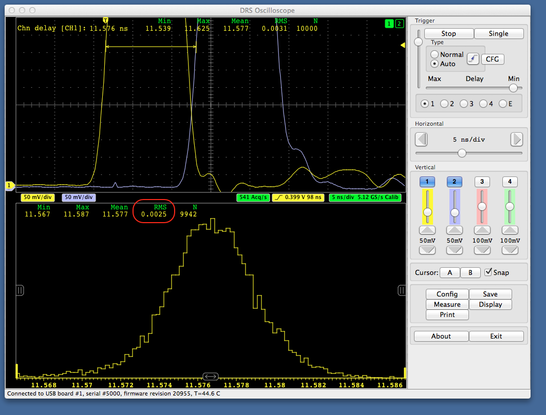
Using more sophisticated algorithms such as cross-correlation, resolutions below 1 ps were already achieved.
The new board can now be ordered at the same price than the V4 board, delivery will start in March 2014.
Best regards,
Stefan Ritt
|
|
Tue Feb 18 14:12:37 2014, Stefan Ritt, Announcement of new Evaluation Board V5
|
| Stefan Ritt wrote: |
|
Dear DRS community,
starting from this year, we ship the new evaluation board V5. This board has an improved internal timing calibration, with which one can measure the time with a precision down to a few ps. Following picture shows the time between two pulses, obtained with a function generator, a passive split and a delay cable. The single threshold time estimator of the DRSOsc program obtains with such signal a resolution of 2.5 ps (RMS).
Using more sophisticated algorithms such as cross-correlation, resolutions below 1 ps were already achieved.
The new board can now be ordered at the same price than the V4 board, delivery will start in March 2014.
Best regards,
Stefan Ritt
|
The new software for the V5 evaluation board has been released today with following new features:
- Hardware scalers for all four channels and the trigger working up to 200 MHz. With the trigger scaler one can measure for example coincidence rates between two channels.
- New vertical and horizontal "slice" measurements. This allows to measure the amplitude of a signal at a certain time relative to the trigger point or the time when a signal crosses a certain level.
- Gated charge measurement allowing to measure the charge of a signal between two time markers, like an old-fashioned charge integrating ADC.
The software is available at the the usual location http://www.psi.ch/drs/software-download for Linux, Windows and Mac OSX. I'm working right now to get it also into the Apple App Store.
/Stefan |
|
Mon Jun 9 12:03:26 2014, Osip Lishilin, Announcement of new Evaluation Board V5
|
| Stefan Ritt wrote: |
|
Hardware scalers for all four channels and the trigger working up to 200 MHz. With the trigger scaler one can measure for example coincidence rates between two channels.
|
Does it give the ability to measure triggering rate? I'm talking again about possibility of use DRS4 as pulse counter for PMT's. If yes, do I need new v5 board or it is possible to use v4 board? |
|
Wed Jun 11 11:13:50 2014, Stefan Ritt, Announcement of new Evaluation Board V5
|
| Osip Lishilin wrote: |
|
| Stefan Ritt wrote: |
|
Hardware scalers for all four channels and the trigger working up to 200 MHz. With the trigger scaler one can measure for example coincidence rates between two channels.
|
Does it give the ability to measure triggering rate? I'm talking again about possibility of use DRS4 as pulse counter for PMT's. If yes, do I need new v5 board or it is possible to use v4 board?
|
Yes it is possible to measure the raw trigger rate, with a resolution of 10 Hz. You need a new V5 board for that. |
|
Mon Jun 16 15:35:59 2014, Osip Lishilin, Announcement of new Evaluation Board V5
|
| Stefan Ritt wrote: |
|
| Osip Lishilin wrote: |
|
| Stefan Ritt wrote: |
|
Hardware scalers for all four channels and the trigger working up to 200 MHz. With the trigger scaler one can measure for example coincidence rates between two channels.
|
Does it give the ability to measure triggering rate? I'm talking again about possibility of use DRS4 as pulse counter for PMT's. If yes, do I need new v5 board or it is possible to use v4 board?
|
Yes it is possible to measure the raw trigger rate, with a resolution of 10 Hz. You need a new V5 board for that.
|
I'm not sure if I understand you correctly. The trigger rate could be up to 200 MHz, and it's possible to measure it with 10 Hz resolution. Is it right?
Does it possible to measure independent trigger rate for each channel? |
|
Thu May 29 04:22:43 2014, Toshihiro Nonaka, CalibrationWaveform
|
I'm writing the drs_exam.cpp to use multi-boards(v3, firmware:4.0.0), and taking data succeeded. But I have several questions about function written in DRS.cpp.
- I wrote following code in drs_exam.cpp to set input range -0.4~0.6
b1->SetInputRange(0.1);
And the 100mV offset appeared(I attached a picture). I think this is due to the voltage calibration isn't done.(Calibrated to -0.5~0.5mV in DRS Oscilloscope)
If so, could you show me a simple usage of "CalibrationWaveform()" function in DRS.cpp? (or other function?)
2. Although this question might be the almost same with above, is there any way to execute voltage and timing calibration in drs_exam.cpp?
Now I start DAQ by executing drs_exam.cpp after I execute voltage and timing calibration to each board by DRS Oscilloscope program.
3. Which command is right to use external trigger?
b1->SetTriggerSource(4); or b1->SetTriggerSource(1<<4);
Best regards,
Toshihiro Nonaka |
|
Thu Jun 12 17:16:13 2014, Stefan Ritt, CalibrationWaveform
|
| Toshihiro Nonaka wrote: |
|
I'm writing the drs_exam.cpp to use multi-boards(v3, firmware:4.0.0), and taking data succeeded. But I have several questions about function written in DRS.cpp.
- I wrote following code in drs_exam.cpp to set input range -0.4~0.6
b1->SetInputRange(0.1);
And the 100mV offset appeared(I attached a picture). I think this is due to the voltage calibration isn't done.(Calibrated to -0.5~0.5mV in DRS Oscilloscope)
If so, could you show me a simple usage of "CalibrationWaveform()" function in DRS.cpp? (or other function?)
2. Although this question might be the almost same with above, is there any way to execute voltage and timing calibration in drs_exam.cpp?
Now I start DAQ by executing drs_exam.cpp after I execute voltage and timing calibration to each board by DRS Oscilloscope program.
3. Which command is right to use external trigger?
b1->SetTriggerSource(4); or b1->SetTriggerSource(1<<4);
Best regards,
Toshihiro Nonaka
|
1. b->CalibrateVolt(NULL);
2. see 1.
3. For the V3 boards use b->SetTriggerSource(4), for V4 and V5 boards, use b->SetTriggerSource(1<<4). I had to change that because from V4 on we can have logical combinations between channels (like channel 1 AND channel 2).
Best regards,
Stefan |
|
Thu Jun 12 12:40:03 2014, Roman Gredig, DRS eval bord v5 Timing
|
Dear Stefan

I have two questions concerning the best time resolution with the DRS V5 eval board.
a) Calibration:
I am using 4 boards daisy chained. To achieve optimal time resolution I did first a voltage calibration and right afterwards a time calibration. For all
boards after the master I am not sure how to do it.
After setting the flag "Configure multi-board daisy-chain" in the config menu, all the slave boards set the flag "use external reference clock".  By
hitting the voltage calibration button, the slave boards unset this flag. Is it true, that I have to re-set this before doing the time-calibration right
afterwards?


b) getting the right times in binary format:
To get the time out of the time width (i.e. the t_ch[i]) you sum up in your documentation from j=0 to j=i (see attachment). In your example code
read_binary.cpp (line 113) you sum from j=0 to j=i-1. Since you get the the bin with in the binary file, I guess that the example code is correct one?

Thank you very much,
Cheers,
Roman |
|
Thu Jun 12 12:46:00 2014, Stefan Ritt, DRS eval bord v5 Timing
|
> a) Calibration:
> I am using 4 boards daisy chained. To achieve optimal time resolution I did first a voltage calibration and right afterwards a time calibration. For all
> boards after the master I am not sure how to do it.
> After setting the flag "Configure multi-board daisy-chain" in the config menu, all the slave boards set the flag "use external reference clock".  By
> hitting the voltage calibration button, the slave boards unset this flag. Is it true, that I have to re-set this before doing the time-calibration right
> afterwards?

Please do NOT do any calibration in multi-board mode. This will not work. Calibrate the boards separately, then activate the multi-board mode. Please note that the timing between the boards is not better
than ~50 ps. This is a limitation of the FPGA clock generators. If you need better timing, you have to feed an external clock into one channel of each board (leaving only 3 channels for DAQ). The upcoming
WaveDREAM board will have 16 channels per board, so building bigger DAQ systems will be much easier (and more precise).

> b) getting the right times in binary format:
> To get the time out of the time width (i.e. the t_ch[i]) you sum up in your documentation from j=0 to j=i (see attachment). In your example code
> read_binary.cpp (line 113) you sum from j=0 to j=i-1. Since you get the the bin with in the binary file, I guess that the example code is correct one?

Yes, I will correct the documentation.

Cheers,
Stefan |
|
Tue May 27 13:46:18 2014, Dominik Neise, Spikes in DRS4 data on custom baord.
|
We see quite some spikes in our DRS4 sampled data in FACT. We see different types of spikes:
- single cell spikes, usually showing a large amplitude of 200mV
- double cell spikes, usually only in the order of 20mV.
- Even triple and quadro cell spikes are rarely seen.
The double cell spikes often occur as symmetrical double cell spikes mirrored at cell 512. quadro cell spikes seem to be nothing else, than connected symmetrical double cell spikes. For the triple cell spikes we have no idea.
Currently we use simple filters to get rid of these spikes, this workes rather well for the large single cell spikes, but with the occurance of tripples and quadros we started to worry about higher multiples and revived our DRS4 spike investigations.
Now I was told, that you Stefan know already where these spikes come from and even a paper exisits. Unfortunately so far I was unable to find it.
I wonder if it is possible to predict the occurance of these spikes, so one does not have to search for them anymore and can get rid of the filters.
Best regards
Dominik |
|
Tue May 27 16:07:17 2014, Stefan Ritt, Spikes in DRS4 data on custom baord.
|
| Dominik Neise wrote: |
|
We see quite some spikes in our DRS4 sampled data in FACT. We see different types of spikes:
- single cell spikes, usually showing a large amplitude of 200mV
- double cell spikes, usually only in the order of 20mV.
- Even triple and quadro cell spikes are rarely seen.
The double cell spikes often occur as symmetrical double cell spikes mirrored at cell 512. quadro cell spikes seem to be nothing else, than connected symmetrical double cell spikes. For the triple cell spikes we have no idea.
Currently we use simple filters to get rid of these spikes, this workes rather well for the large single cell spikes, but with the occurance of tripples and quadros we started to worry about higher multiples and revived our DRS4 spike investigations.
Now I was told, that you Stefan know already where these spikes come from and even a paper exisits. Unfortunately so far I was unable to find it.
I wonder if it is possible to predict the occurance of these spikes, so one does not have to search for them anymore and can get rid of the filters.
Best regards
Dominik
|
All I know is that the "20mV" spikes are always symmetrical around cell #512, that they are typically 17.4 mV in height, and that they occur always in all 9 channels simultaneously. They cannot occur in all locations, but there only like 32 possible locations where they can occur. With this information it should be easy to fix them by filtering.
200 mV spikes are new to me. I do not see them in our boards, so it must be related to the board readout and not to the chip.
Best regards,
Stefan
|
|
Fri May 16 14:04:47 2014, Benjamin LeGeyt, simultaneous writing and reading with region of interest mode?
|
Hello!
We're developing electronics based on the DRS4 to read out a breast PET scanner and our event rate will be quite high so we're concerned about dead-time. with that in mind, I have a question regarding the mode of simultaneous writing and reading that is described in the DRS4 data sheet. I think the description there is quite clear but I'd like to ask for a few clarifications.
1) Are the channels required to be read out via the channel multiplexer when doing the simultaneous write/read or is it ok to read out all channels in parallel (even the ones still sampling) and just throw away the ones you don't want?
2) If one wanted to use region of interest mode along with the simultaneous write/read, how would that work? Here is what I would think - please tell me if I'm missing some important detail:
-upon trigger, deassert dwrite.
-strobe RSRLOAD
-increment write config register
-reassert dwrite
-start the readout (reading out stop shift register value on SROUT as data comes out)
3) now to add even more complexity - I would actually like to use simultaneous write/read along with region of interest mode and also with pairs of cascaded channels as we need >500ns latency and 2Gsps is too slow for our signals. the combination of cascading and simultaneous write/read is addressed in the data sheet but I still have one question. In normal circumstances when cascading channels, one would read out the value in the write shift register to know which channel was active when the domino wave stopped. I assume that this is not possible when dwrite is enabled as the write shift register is then advanced by the domino wave, so I see three possibilities:
-accept more dead-time and read out the write-shift-register each time (adds ~240ns to deadtime)
-just read out both channels every time and figure out later where is the data you want
-attempt to keep track of the expected state of write-shift-register in firmware.
is there a better option that I have not thought of?
many thanks!
Benjamin LeGeyt |
|
Mon May 19 08:04:57 2014, Stefan Ritt, simultaneous writing and reading with region of interest mode?
|
| Benjamin LeGeyt wrote: |
|
Hello!
We're developing electronics based on the DRS4 to read out a breast PET scanner and our event rate will be quite high so we're concerned about dead-time. with that in mind, I have a question regarding the mode of simultaneous writing and reading that is described in the DRS4 data sheet. I think the description there is quite clear but I'd like to ask for a few clarifications.
1) Are the channels required to be read out via the channel multiplexer when doing the simultaneous write/read or is it ok to read out all channels in parallel (even the ones still sampling) and just throw away the ones you don't want?
2) If one wanted to use region of interest mode along with the simultaneous write/read, how would that work? Here is what I would think - please tell me if I'm missing some important detail:
-upon trigger, deassert dwrite.
-strobe RSRLOAD
-increment write config register
-reassert dwrite
-start the readout (reading out stop shift register value on SROUT as data comes out)
3) now to add even more complexity - I would actually like to use simultaneous write/read along with region of interest mode and also with pairs of cascaded channels as we need >500ns latency and 2Gsps is too slow for our signals. the combination of cascading and simultaneous write/read is addressed in the data sheet but I still have one question. In normal circumstances when cascading channels, one would read out the value in the write shift register to know which channel was active when the domino wave stopped. I assume that this is not possible when dwrite is enabled as the write shift register is then advanced by the domino wave, so I see three possibilities:
-accept more dead-time and read out the write-shift-register each time (adds ~240ns to deadtime)
-just read out both channels every time and figure out later where is the data you want
-attempt to keep track of the expected state of write-shift-register in firmware.
is there a better option that I have not thought of?
many thanks!
Benjamin LeGeyt
|
Unfortunately the simultaneous writing/reading does not work as described in the data sheet. Just recently we found out that due to a bug in the chip a part of the waveform is missing if you read and write at the same time. The only clean solution is to use two DRS4 chips in parallel. You read one chip while the other samples, then you switch over between them. In that case all the ROI scheme and channel cascading works normally. The dead time will be addressed by the DRS5 chip, which will be dead time free, but will not be available until in maybe 2-3 years.
/Stefan |
|
Tue Apr 15 18:35:41 2014, Carlo Stella, drs_exam project fail to compile
|
Hi,
when I try to compile drs_exam project my computer give me this output:
1>------ Rebuild All started: Project: drs_exam, Configuration: Debug Win32 ------
1> averager.cpp
1>c:\users\daq\desktop\
original drs\drs5\src\averager.cpp(165): warning C4996: 'fopen': This function or variable may be unsafe. Consider using fopen_s instead. To disable deprecation, use _CRT_SECURE_NO_WARNINGS. See online help for details.
1> c:\program files (x86)\microsoft visual studio 10.0\vc\include\stdio.h(234) : see declaration of 'fopen'
1> DRS.cpp
1>c:\users\daq\desktop\original drs\drs5\src\drs.cpp(4597): warning C4244: '=' : conversion from 'double' to 'float', possible loss of data
1> drs_exam.cpp
1> Generating Code...
1> musbstd.c
1> mxml.c
1> strlcpy.c
1> Generating Code...
1>musbstd.obj : error LNK2019: unresolved external symbol _usb_claim_interface referenced in function _musb_open
1>musbstd.obj : error LNK2019: unresolved external symbol _usb_set_configuration referenced in function _musb_open
1>musbstd.obj : error LNK2019: unresolved external symbol _usb_open referenced in function _musb_open
1>musbstd.obj : error LNK2019: unresolved external symbol _usb_get_busses referenced in function _musb_open
1>musbstd.obj : error LNK2019: unresolved external symbol _usb_set_debug referenced in function _musb_open
1>musbstd.obj : error LNK2019: unresolved external symbol _usb_find_devices referenced in function _musb_open
1>musbstd.obj : error LNK2019: unresolved external symbol _usb_find_busses referenced in function _musb_open
1>musbstd.obj : error LNK2019: unresolved external symbol _usb_init referenced in function _musb_open
1>musbstd.obj : error LNK2019: unresolved external symbol _usb_set_altinterface referenced in function _musb_set_altinterface
1>musbstd.obj : error LNK2019: unresolved external symbol _usb_close referenced in function _musb_close
1>musbstd.obj : error LNK2019: unresolved external symbol _usb_release_interface referenced in function _musb_close
1>musbstd.obj : error LNK2019: unresolved external symbol _usb_bulk_write referenced in function _musb_write
1>musbstd.obj : error LNK2019: unresolved external symbol _usb_bulk_read referenced in function _musb_read
1>musbstd.obj : error LNK2019: unresolved external symbol _usb_reset referenced in function _musb_reset
1>musbstd.obj : error LNK2019: unresolved external symbol _usb_get_descriptor referenced in function _musb_get_device
1>.\Debug/drs_exam.exe : fatal error LNK1120: 15 unresolved externals
========== Rebuild All: 0 succeeded, 1 failed, 0 skipped ==========
Can anyone help me to solve the problem? |
|
Wed Apr 16 08:20:36 2014, Stefan Ritt, drs_exam project fail to compile
|
| Carlo Stella wrote: |
|
Hi,
when I try to compile drs_exam project my computer give me this output:
1>------ Rebuild All started: Project: drs_exam, Configuration: Debug Win32 ------
1> averager.cpp
1>c:\users\daq\desktop\
original drs\drs5\src\averager.cpp(165): warning C4996: 'fopen': This function or variable may be unsafe. Consider using fopen_s instead. To disable deprecation, use _CRT_SECURE_NO_WARNINGS. See online help for details.
1> c:\program files (x86)\microsoft visual studio 10.0\vc\include\stdio.h(234) : see declaration of 'fopen'
1> DRS.cpp
1>c:\users\daq\desktop\original drs\drs5\src\drs.cpp(4597): warning C4244: '=' : conversion from 'double' to 'float', possible loss of data
1> drs_exam.cpp
1> Generating Code...
1> musbstd.c
1> mxml.c
1> strlcpy.c
1> Generating Code...
1>musbstd.obj : error LNK2019: unresolved external symbol _usb_claim_interface referenced in function _musb_open
1>musbstd.obj : error LNK2019: unresolved external symbol _usb_set_configuration referenced in function _musb_open
1>musbstd.obj : error LNK2019: unresolved external symbol _usb_open referenced in function _musb_open
1>musbstd.obj : error LNK2019: unresolved external symbol _usb_get_busses referenced in function _musb_open
1>musbstd.obj : error LNK2019: unresolved external symbol _usb_set_debug referenced in function _musb_open
1>musbstd.obj : error LNK2019: unresolved external symbol _usb_find_devices referenced in function _musb_open
1>musbstd.obj : error LNK2019: unresolved external symbol _usb_find_busses referenced in function _musb_open
1>musbstd.obj : error LNK2019: unresolved external symbol _usb_init referenced in function _musb_open
1>musbstd.obj : error LNK2019: unresolved external symbol _usb_set_altinterface referenced in function _musb_set_altinterface
1>musbstd.obj : error LNK2019: unresolved external symbol _usb_close referenced in function _musb_close
1>musbstd.obj : error LNK2019: unresolved external symbol _usb_release_interface referenced in function _musb_close
1>musbstd.obj : error LNK2019: unresolved external symbol _usb_bulk_write referenced in function _musb_write
1>musbstd.obj : error LNK2019: unresolved external symbol _usb_bulk_read referenced in function _musb_read
1>musbstd.obj : error LNK2019: unresolved external symbol _usb_reset referenced in function _musb_reset
1>musbstd.obj : error LNK2019: unresolved external symbol _usb_get_descriptor referenced in function _musb_get_device
1>.\Debug/drs_exam.exe : fatal error LNK1120: 15 unresolved externals
========== Rebuild All: 0 succeeded, 1 failed, 0 skipped ==========
Can anyone help me to solve the problem?
|
Have a look at the web site http://www.psi.ch/drs/software-download . Under the MS Windows section it says that you have to install the libusb-1.0 package first before you can compile the example program. This is also obvious from the missing _usb_* functions in the error listing above.
/Stefan |
|
Thu Apr 24 23:03:25 2014, Carlo Stella, drs_exam project fail to compile
|
| Stefan Ritt wrote: |
|
| Carlo Stella wrote: |
|
Hi,
when I try to compile drs_exam project my computer give me this output:
1>------ Rebuild All started: Project: drs_exam, Configuration: Debug Win32 ------
1> averager.cpp
1>c:\users\daq\desktop\
original drs\drs5\src\averager.cpp(165): warning C4996: 'fopen': This function or variable may be unsafe. Consider using fopen_s instead. To disable deprecation, use _CRT_SECURE_NO_WARNINGS. See online help for details.
1> c:\program files (x86)\microsoft visual studio 10.0\vc\include\stdio.h(234) : see declaration of 'fopen'
1> DRS.cpp
1>c:\users\daq\desktop\original drs\drs5\src\drs.cpp(4597): warning C4244: '=' : conversion from 'double' to 'float', possible loss of data
1> drs_exam.cpp
1> Generating Code...
1> musbstd.c
1> mxml.c
1> strlcpy.c
1> Generating Code...
1>musbstd.obj : error LNK2019: unresolved external symbol _usb_claim_interface referenced in function _musb_open
1>musbstd.obj : error LNK2019: unresolved external symbol _usb_set_configuration referenced in function _musb_open
1>musbstd.obj : error LNK2019: unresolved external symbol _usb_open referenced in function _musb_open
1>musbstd.obj : error LNK2019: unresolved external symbol _usb_get_busses referenced in function _musb_open
1>musbstd.obj : error LNK2019: unresolved external symbol _usb_set_debug referenced in function _musb_open
1>musbstd.obj : error LNK2019: unresolved external symbol _usb_find_devices referenced in function _musb_open
1>musbstd.obj : error LNK2019: unresolved external symbol _usb_find_busses referenced in function _musb_open
1>musbstd.obj : error LNK2019: unresolved external symbol _usb_init referenced in function _musb_open
1>musbstd.obj : error LNK2019: unresolved external symbol _usb_set_altinterface referenced in function _musb_set_altinterface
1>musbstd.obj : error LNK2019: unresolved external symbol _usb_close referenced in function _musb_close
1>musbstd.obj : error LNK2019: unresolved external symbol _usb_release_interface referenced in function _musb_close
1>musbstd.obj : error LNK2019: unresolved external symbol _usb_bulk_write referenced in function _musb_write
1>musbstd.obj : error LNK2019: unresolved external symbol _usb_bulk_read referenced in function _musb_read
1>musbstd.obj : error LNK2019: unresolved external symbol _usb_reset referenced in function _musb_reset
1>musbstd.obj : error LNK2019: unresolved external symbol _usb_get_descriptor referenced in function _musb_get_device
1>.\Debug/drs_exam.exe : fatal error LNK1120: 15 unresolved externals
========== Rebuild All: 0 succeeded, 1 failed, 0 skipped ==========
Can anyone help me to solve the problem?
|
Have a look at the web site http://www.psi.ch/drs/software-download . Under the MS Windows section it says that you have to install the libusb-1.0 package first before you can compile the example program. This is also obvious from the missing _usb_* functions in the error listing above.
/Stefan
|
Hi Stefan,
you were right, I forgot to install the libusb driver.
Thanks for your support |
|
Thu Apr 17 12:02:28 2014, Wang , The first channel is wrong.
|
Hi,
I want to describe this phenomenon again. The diagram below is DRS4 output. There is no input signal. Green is the output8+, blue is the output8-. Output8+ of the first channel is below the baseline. The output is saturation when input ADC. It is not right, and what is it in front of the first channel? It seemed there are two channels. Others channel is suitable. I check the circuit , Hardware is no problem, so I want to konw where the FPGA code is wrong. What reason is caused? Can anyone help me to solve the problem? Thanks! |
|
Thu Apr 10 14:45:12 2014, Roman Gredig, DRS4 Evalboard V5 with Windows7Pro64bit
|
Dear Stefan

I am trying to use the DRS4 eval board on a Windows7 machine. Unfortunately I get an error message saying "No DRS
board found". But I can see the DRS board in the device manager with the proper driver loaded. Is there any known
problem with win7?

I am using windows7 professional (SP1) with the drs software 5.0.1.

Cheers,
Roman

PS: Everything is working on my mac. But not under windows7. |
|
Wed Apr 16 10:24:55 2014, Stefan Ritt, DRS4 Evalboard V5 with Windows7Pro64bit
|
>
> Dear Stefan
>
> I am trying to use the DRS4 eval board on a Windows7 machine. Unfortunately I get an error message saying "No DRS
> board found". But I can see the DRS board in the device manager with the proper driver loaded. Is there any known
> problem with win7?
>
> I am using windows7 professional (SP1) with the drs software 5.0.1.
>
> Cheers,
> Roman
>
> PS: Everything is working on my mac. But not under windows7.

Hi Roman,

please read section 2.3. (page 13)  from the Evaluation Board manual: http://www.psi.ch/drs/DocumentationEN/manual_rev50.pdf

You have to update the USB driver in your Computer Management.

Cheers,
Stefan |
|
Wed Apr 16 03:22:43 2014, Wang , why is the first channel output error?
|
Hi,
The diagram below is DRS4 output. Green is the output8+, blue is the output8-. Output8+ of the first channel is below the baseline. It is not right.
Others channel is suitable. I check the circuit , Hardware is no problem, so I want to konw where the FPGA code is wrong. what reason is caused? Thanks! |
|
Wed Apr 16 08:30:32 2014, Stefan Ritt, why is the first channel output error?
|
| Wang wrote: |
|
Hi,
The diagram below is DRS4 output. Green is the output8+, blue is the output8-. Output8+ of the first channel is below the baseline. It is not right.
Others channel is suitable. I check the circuit , Hardware is no problem, so I want to konw where the FPGA code is wrong. what reason is caused? Thanks!
|
You are funny. Just by looking at a scope picture I should know what is wrong at your FPGA code. Unfortunately I'm not a magician. I looks to me like you have 11 channels in your diagram, although the chip has only 9. What I would recommend is to put some input to each channel one at a time, like a 10 MHz sine wave. You should then see that sine wave for the single channel at the output and can correlate input vs. output. Maybe your address bits are wrong or the chip has a soldering problem.
/Stefan |
|