 Mon Feb 29 13:33:06 2016, Dmitry Hits, two DRS4 boards configuration with 2048 samples each Mon Feb 29 13:33:06 2016, Dmitry Hits, two DRS4 boards configuration with 2048 samples each
|
Dear Stefan,
I daisy-chained two boards (master sn#: 2514 - slave sn#: 2513) each with 2048 samples. However, when I use drsosc and put check mark in "configure multi-board daisy-chain" I see only 1024 samples. Namely, the first 1024 samples, the last part is missing. When I remove this check mark, I see all 2048 samples. Is there a simple software fix for this or is it a more involved firmware limitation?
Other parameters: software version: 5.0.4, firmware version 21305, configured for 0.7 GSPS, display at 500 ns/div
Thank you,
Dmitry Hits. |
 Mon Feb 29 14:09:21 2016, Stefan Ritt, two DRS4 boards configuration with 2048 samples each Mon Feb 29 14:09:21 2016, Stefan Ritt, two DRS4 boards configuration with 2048 samples each
|
The multi-board mode has never been tested with 2048 samples, so is very likely not to work. I don't know yet how much work this will be to fix, but I'm on a business trip the next three weeks and probably will only have time to look at it when I return.
Stefan
| Dmitry Hits wrote: |
|
Dear Stefan,
I daisy-chained two boards (master sn#: 2514 - slave sn#: 2513) each with 2048 samples. However, when I use drsosc and put check mark in "configure multi-board daisy-chain" I see only 1024 samples. Namely, the first 1024 samples, the last part is missing. When I remove this check mark, I see all 2048 samples. Is there a simple software fix for this or is it a more involved firmware limitation?
Other parameters: software version: 5.0.4, firmware version 21305, configured for 0.7 GSPS, display at 500 ns/div
Thank you,
Dmitry Hits.
|
|
|
Mon May 2 14:31:28 2016, Dmitry Hits, two DRS4 boards configuration with 2048 samples each
|
Hi Stefan
Any chance you have time to fix the software for multiboard configuration with 2048 samples each. I tried 5.0.5, but drsosc still shows only half of the waveform.
Dmitry
| Stefan Ritt wrote: |
|
The multi-board mode has never been tested with 2048 samples, so is very likely not to work. I don't know yet how much work this will be to fix, but I'm on a business trip the next three weeks and probably will only have time to look at it when I return.
Stefan
| Dmitry Hits wrote: |
|
Dear Stefan,
I daisy-chained two boards (master sn#: 2514 - slave sn#: 2513) each with 2048 samples. However, when I use drsosc and put check mark in "configure multi-board daisy-chain" I see only 1024 samples. Namely, the first 1024 samples, the last part is missing. When I remove this check mark, I see all 2048 samples. Is there a simple software fix for this or is it a more involved firmware limitation?
Other parameters: software version: 5.0.4, firmware version 21305, configured for 0.7 GSPS, display at 500 ns/div
Thank you,
Dmitry Hits.
|
|
|
Wed May 11 15:48:57 2016, SANDJONG Saturnin Orly, Probl�me de Calibration de la DRS4 
|
Bonjour, Je suis en stage dans un laboratoire ou on utilise pour echantillonnage des données, une cartes DRS4 5GSPS avec 1024 cell, mon probléme réside dans la partie Calibration en tension selon l'article "Novel Calibration Method for Switched Capacitor Arrays Enables Time Measurements with Sub-Picosecond Resolution".
En fait je ne comprends pas précisément ces 3 parties de la calibration en tension. Quelqu'un pourras t-il s'il vous plait m'expliquer assez clairement avec des exemples comment il faut s'y prendre?
Merci et bien Cordialement. |
|
Thu May 12 05:18:47 2016, Yu, Problem For Software Download
|
Hi
I can't download the software for windows on this website 'www.psi.ch/drs/software-download', there is some mistake when i click on download.
If convenient, can you send the software Version 5.0.5 for windows to me? My E-mail address is 'yuhaiyang421@163.com'. Thank you!
Best Regards
Yu |
|
Thu May 12 08:16:41 2016, Stefan Ritt, Problem For Software Download
|
Can you tell me (screendump) what is the problem on the web site https://www.psi.ch/drs/software-download ? It should redirect you to
https://www.dropbox.com/sh/qul1cgtm4x7zx13/AADKQ-qGQGdAHPu6OR3vTNY0a?dl=0
for the Windows download.
I cannot send executables via email, that won't go though any spam filter.
Stefan
| Yu wrote: |
|
Hi
I can't download the software for windows on this website 'www.psi.ch/drs/software-download', there is some mistake when i click on download.
If convenient, can you send the software Version 5.0.5 for windows to me? My E-mail address is 'yuhaiyang421@163.com'. Thank you!
Best Regards
Yu
|
|
|
Wed May 11 04:01:14 2016, Maksat, DRS4 Macro to save events
|
Dear Stefan,
I am trying to setup DRS inside radiation enclosure and would like to write a simple script that will automatically save certain number of events.
Could you please point to me an example that can I use for Mac OS? I saw there is drs_exam.cpp in the directory but was not able to get work in Mac OS. Any help would be greatly appreciated.
Thanks
|
|
Thu May 12 12:38:17 2016, Stefan Ritt, DRS4 Macro to save events
|
Dear Maksat,
If your car does not run, and you call the car dealer and tell him "my car does not run", what will the car dealer ask you? Eh... ? Right ! He will ask "what are the symptoms, what did you try, what did and what did not work". Here it's the same. "was not able to get it work" is not a valid statement, since I have absolutely no idea what did not work and what you did try.
The official way is to follow the instruction in the evlauation board manual on section 2.4 - Installation under Linux. If that does not work, please be a bit more precise what errors you get.
Cheers,
Stefan
| Maksat wrote: |
|
Dear Stefan,
I am trying to setup DRS inside radiation enclosure and would like to write a simple script that will automatically save certain number of events.
Could you please point to me an example that can I use for Mac OS? I saw there is drs_exam.cpp in the directory but was not able to get work in Mac OS. Any help would be greatly appreciated.
Thanks
|
|
|
Wed Jun 1 22:29:01 2016, Dominik Neise, problems when stop cell >= 767 ??
|
Hello Stefan,
some colleages told me a story, I was neither able to confirm nor find anything in the datsheet about. According to them:
For some internal reason of the DRS4, if the “stop capacitor” of the DRS4 is >= 767, the true stop channel is one before the stop channel read from the DRS4. In other words, the stop channel which returns the DRS4 shifts after sampling to the capacitor ID 766.
Can you confirm that, or even say a few words about that matter?
I wanted to confirm this by plotting the stop cell distribution for random triggered data, taken with one of the FACT boards. I assumed (possibly misunderstanding the matter), that this would lead to missing values in the area of stop cell 767, but cannot see any significant excess or lack of entries in that area.
|
|
Wed Jun 1 23:16:01 2016, Stefan Ritt, problems when stop cell >= 767 ??
|
I cannot confirm the story with the "stop capacitor > 767". It can be seen from your plots that the distribution of stop cells are even, no holes or bins with double height.
There is an issue with cell 767, but this is when one tries to do simultaneous reading/writing to the chip. This does not really work as writen in the data sheet. Waveforms sometimgs get cut off at cell 767. But the stop cell is always correct, otherwise one could not calibrate the data. If you use the evaluation board for example, which is perfectly calibrated, and introduce an "artifical" shift like
if stop cell > 767 then
stop cell = stop cell + 1
then you would see that the voltage calibration would become wrong and very noisy.
Stefan
| Dominik Neise wrote: |
|
Hello Stefan,
some colleages told me a story, I was neither able to confirm nor find anything in the datsheet about. According to them:
For some internal reason of the DRS4, if the “stop capacitor” of the DRS4 is >= 767, the true stop channel is one before the stop channel read from the DRS4. In other words, the stop channel which returns the DRS4 shifts after sampling to the capacitor ID 766.
Can you confirm that, or even say a few words about that matter?
I wanted to confirm this by plotting the stop cell distribution for random triggered data, taken with one of the FACT boards. I assumed (possibly misunderstanding the matter), that this would lead to missing values in the area of stop cell 767, but cannot see any significant excess or lack of entries in that area.
|
|
|
Sun Jun 12 08:49:54 2016, Michael, problems of DRS4
|
Hi
I want to use DRS4 to digitize 16 channels of signals. The width of signal is about 20 ns, with frequency of 50Hz. The time differences between these 16 signals are not constant, arranging from 3us to 0. I am confused about this in some aspects.
- Can I use SIMULTANEOUS WRITINT AND READING to realize this? I saw the VHDL program, and if I understand it correctly, it did not work at this state.
- Or sampling at 1GSPS, using CASCADING OF CHANNELS, I can sample signal at most 4us or 8us, then digitizing all signals of one chip. Have you tested 4 or more channels cascading before?
Besides, any advice will be helpful!
Thank you. |
|
Sun Jun 12 08:45:52 2016, Michael, problems of DRS4
|
Hi
I want to use DRS4 to digitize 16 channels of signals. The width of signal is about 20 ns, with frequency of 50Hz. The time differences between these 16 signals are not constant, arranging from 3us to 0. I am confused about this in some aspects.
- Can I use SIMULTANEOUS WRITINT AND READING to realize this? I saw the VHDL program, and if I understand it correctly, it did not work at this state.
- Or sampling at 1GSPS, using CASCADING OF CHANNELS, I can sample signal at most 4us or 8us, then digitizing all signals of one chip. Have you tested 4 or more channels cascading before?
Besides, any advice will be helpful!
Thank you. |
|
Wed Jun 15 14:49:00 2016, Stefan Ritt, problems of DRS4
|
1. Simultaneous writing and reading is not possible with the DRS4 chip. The manual says differently on p. 14, but due to a bug in the chip waveforms get clipped at the end if one does that. We hopt to fix this problem in a future version of the chip.
2. You can cascade 2,4 or 8 channels. If you cascade 8 channels and run at 1 GSPS, you digitize a window of 8 us. If you have 16 signals, you then need 16 chips.
/Stefan
| Michael wrote: |
|
Hi
I want to use DRS4 to digitize 16 channels of signals. The width of signal is about 20 ns, with frequency of 50Hz. The time differences between these 16 signals are not constant, arranging from 3us to 0. I am confused about this in some aspects.
- Can I use SIMULTANEOUS WRITINT AND READING to realize this? I saw the VHDL program, and if I understand it correctly, it did not work at this state.
- Or sampling at 1GSPS, using CASCADING OF CHANNELS, I can sample signal at most 4us or 8us, then digitizing all signals of one chip. Have you tested 4 or more channels cascading before?
Besides, any advice will be helpful!
Thank you.
|
|
|
Wed Jun 29 09:10:01 2016, Stefan Ritt, Negative input signals
|
Hello everybody,
I get often asked if the DRS4 evaluation board can accomodate negative input pulses going to -1V. This is unfortunately not possible, since the board is mainly for evaluation of the DRS4 chip and should not be seen as a complete oscilloscope with flexible input stage. So the maximum it can do is -0.5V to +0.5V or 0V to 1V. For -1V signals, one can use however a passive inverter like this one:
http://www.phillipsscientific.com/pdf/460ds.pdf
And for signals going furhter (-2V, -10V) one can use a passive attenuator like this one:
http://www.pomonaelectronics.com/pdf/d4108_K5513_101.pdf
Best regards,
Stefan
|
|
Mon Aug 29 09:36:34 2016, benjamin legeyt, increment write config register on the fly?
|
Hello,
I have a question about using the write config register to enable/disable sampling on the fly. I am looking to instrument an experiment at EPFL where multiple short events need to be captured during a 20us period followed by an 80us quiet period during which we could read out the chip. Would it be possible to start an acquisition with all channels seeing the same signal and the write config register set to 111111111 and then shift a zero into the write config reg after each event is detected to freeze the channels in time one-by-one? In this way we could measure up to 8 different events during the active period and then read them all out together during the quiet period. I have read the posts about the simultaneous read-write mode and the issue with waveforms stopping at cell 767. not knowing the exact details of what causes this issue I wonder if it would effect this sort of operation? Also, I would like to know if dwrite must be de-asserted while the write config register is being updated or if it could be done while the sampling is active? The latter would obviously be preferable as we would not incur any dead-time during the active period.
Thanks in advance for the information,
Benjamin LeGeyt |
|
Mon Aug 29 10:57:33 2016, Stefan Ritt, increment write config register on the fly?
|
The issue with "stopping at cell 767" would also affect this mode of operation. Furthermore, the DRS4 chip has only 10 bit register which records in which cell the event has occured, and where the readout must be started. If you record 8 separate events, you don't know where to start the readout.
The DRS5 chip will have all this possibilitied, but unfortunately it won't be ready before 2-3 years from now.
Stefan
| benjamin legeyt wrote: |
|
Hello,
I have a question about using the write config register to enable/disable sampling on the fly. I am looking to instrument an experiment at EPFL where multiple short events need to be captured during a 20us period followed by an 80us quiet period during which we could read out the chip. Would it be possible to start an acquisition with all channels seeing the same signal and the write config register set to 111111111 and then shift a zero into the write config reg after each event is detected to freeze the channels in time one-by-one? In this way we could measure up to 8 different events during the active period and then read them all out together during the quiet period. I have read the posts about the simultaneous read-write mode and the issue with waveforms stopping at cell 767. not knowing the exact details of what causes this issue I wonder if it would effect this sort of operation? Also, I would like to know if dwrite must be de-asserted while the write config register is being updated or if it could be done while the sampling is active? The latter would obviously be preferable as we would not incur any dead-time during the active period.
Thanks in advance for the information,
Benjamin LeGeyt
|
|
|
Mon Aug 29 12:18:49 2016, benjamin legeyt, increment write config register on the fly?
|
If I may trouble you for a little more information, the critical point then is that there should not be any zeroes in the write config register while the sampling is active? In case it was unclear I would only be reading out once sampling was stopped (dwrite = 0).
As for the readout, I know that I would have to read out all 1024 samples each time, and keep track of where each channel stopped in the FPGA. I would never know the exact cell where sampling stopped but I hoped that if I discard some number of cells on each side of the expected stopping point that I would be OK.
Thanks again
| Stefan Ritt wrote: |
|
The issue with "stopping at cell 767" would also affect this mode of operation. Furthermore, the DRS4 chip has only 10 bit register which records in which cell the event has occured, and where the readout must be started. If you record 8 separate events, you don't know where to start the readout.
The DRS5 chip will have all this possibilitied, but unfortunately it won't be ready before 2-3 years from now.
Stefan
| benjamin legeyt wrote: |
|
Hello,
I have a question about using the write config register to enable/disable sampling on the fly. I am looking to instrument an experiment at EPFL where multiple short events need to be captured during a 20us period followed by an 80us quiet period during which we could read out the chip. Would it be possible to start an acquisition with all channels seeing the same signal and the write config register set to 111111111 and then shift a zero into the write config reg after each event is detected to freeze the channels in time one-by-one? In this way we could measure up to 8 different events during the active period and then read them all out together during the quiet period. I have read the posts about the simultaneous read-write mode and the issue with waveforms stopping at cell 767. not knowing the exact details of what causes this issue I wonder if it would effect this sort of operation? Also, I would like to know if dwrite must be de-asserted while the write config register is being updated or if it could be done while the sampling is active? The latter would obviously be preferable as we would not incur any dead-time during the active period.
Thanks in advance for the information,
Benjamin LeGeyt
|
|
|
|
Mon Aug 29 12:51:48 2016, Stefan Ritt, increment write config register on the fly?
|
The problem is when you change the write config register from 11111111 to 01111111, or from 00001111 to 00000111, then the last 256 sampels of the previous channel (in the first case #0, in the scond #4) would be overwritten as soon as dwrite =1 again. So you loose 1/4 ef each channel.
Concerning the readout, indeed you can keep track in the FPGA, but only with a certainty of a few cells. This gives some timing inacccuracy of maybe 10-20 ns, which certainly would be disturbing you.
| benjamin legeyt wrote: |
|
If I may trouble you for a little more information, the critical point then is that there should not be any zeroes in the write config register while the sampling is active? In case it was unclear I would only be reading out once sampling was stopped (dwrite = 0).
As for the readout, I know that I would have to read out all 1024 samples each time, and keep track of where each channel stopped in the FPGA. I would never know the exact cell where sampling stopped but I hoped that if I discard some number of cells on each side of the expected stopping point that I would be OK.
Thanks again
| Stefan Ritt wrote: |
|
The issue with "stopping at cell 767" would also affect this mode of operation. Furthermore, the DRS4 chip has only 10 bit register which records in which cell the event has occured, and where the readout must be started. If you record 8 separate events, you don't know where to start the readout.
The DRS5 chip will have all this possibilitied, but unfortunately it won't be ready before 2-3 years from now.
Stefan
| benjamin legeyt wrote: |
|
Hello,
I have a question about using the write config register to enable/disable sampling on the fly. I am looking to instrument an experiment at EPFL where multiple short events need to be captured during a 20us period followed by an 80us quiet period during which we could read out the chip. Would it be possible to start an acquisition with all channels seeing the same signal and the write config register set to 111111111 and then shift a zero into the write config reg after each event is detected to freeze the channels in time one-by-one? In this way we could measure up to 8 different events during the active period and then read them all out together during the quiet period. I have read the posts about the simultaneous read-write mode and the issue with waveforms stopping at cell 767. not knowing the exact details of what causes this issue I wonder if it would effect this sort of operation? Also, I would like to know if dwrite must be de-asserted while the write config register is being updated or if it could be done while the sampling is active? The latter would obviously be preferable as we would not incur any dead-time during the active period.
Thanks in advance for the information,
Benjamin LeGeyt
|
|
|
|
|
Thu Sep 29 17:26:13 2016, Jacob Hwang, Output Timing Drifting
|
Hello,
I have designed four DRS4 chips (36 channels) on my board running at 1GHz (REFCLK=488.28KHz) and ROI mode. All 4 chips' REFCLK, DWRITE, RSRLOAD, and SRCLK are buffer driven by the same source. SRCLK is set to 40MHz to reduce the readout time.
If I injected a sine waveform, buffered and splitted into all 36 channels,I noticed all 9 channels on each DRS4 chip output almost the same as expected. But the output phase from chip to chip is drifting as shown in attached picture which is from two different channels of different chips. From the few boards I have built, I found few chips are drifting more than the others and is different on every board.
The sympton look like the DRS4 internal PLL is drifting, but I checked the DTAP output on every chip and found it's dead-lock steady even I used persistance setting on my oscilloscope. Do you have any suggestion how to attack this problem? Thank you.
Jacob Hwang
|
|
Fri Sep 30 17:03:38 2016, Stefan Ritt, Output Timing Drifting
|
Hi Jacob,
you are missing the timing calibration. Each sampling cell has not the same width. Running at 5 GSPS, cell widths scatter from 150 ps to 250 ps. If you integrate these widhts, you get a time scale which can be off by a few ns between chips, something you see in your plot. Here is a paper which explains in detail how to do a timing calibration: https://arxiv.org/abs/1405.4975
Cheers,
Stefan
| Jacob Hwang wrote: |
|
Hello,
I have designed four DRS4 chips (36 channels) on my board running at 1GHz (REFCLK=488.28KHz) and ROI mode. All 4 chips' REFCLK, DWRITE, RSRLOAD, and SRCLK are buffer driven by the same source. SRCLK is set to 40MHz to reduce the readout time.
If I injected a sine waveform, buffered and splitted into all 36 channels,I noticed all 9 channels on each DRS4 chip output almost the same as expected. But the output phase from chip to chip is drifting as shown in attached picture which is from two different channels of different chips. From the few boards I have built, I found few chips are drifting more than the others and is different on every board.
The sympton look like the DRS4 internal PLL is drifting, but I checked the DTAP output on every chip and found it's dead-lock steady even I used persistance setting on my oscilloscope. Do you have any suggestion how to attack this problem? Thank you.
Jacob Hwang
|
|
|
Wed Oct 5 22:43:29 2016, Will Flanagan, Timestamp for each DRS4 waveform
|
Hi DRS4 Experts,
I have been analyzing DRS4 binary data with scripts based on Stefan's (very helpful!) macro:
https://midas.psi.ch/elogs/DRS4+Forum/361
I would now like to look at the stability of my waveforms over a long period of time. In order to do this, I would need a timestamp encoded with each waveform. Are there timestamps within default DRS4 binary data? If so, does anyone have sample code for extracting them?
Best Regards,
Will |
|
Thu Oct 6 11:18:05 2016, Stefan Ritt, Timestamp for each DRS4 waveform
|
In the mentioned read_binary.cpp file you have the line where you read the event header
i = fread(&eh, sizeof(eh), 1, f);
The C structure eh now contains the full timestamp, and you can access it with
eh.year

eh.month

eh.day

eh.hour

eh.minute

eh.second

eh.millisecond
Cheers,
Stefan
| Will Flanagan wrote: |
|
Hi DRS4 Experts,
I have been analyzing DRS4 binary data with scripts based on Stefan's (very helpful!) macro:
https://midas.psi.ch/elogs/DRS4+Forum/361
I would now like to look at the stability of my waveforms over a long period of time. In order to do this, I would need a timestamp encoded with each waveform. Are there timestamps within default DRS4 binary data? If so, does anyone have sample code for extracting them?
Best Regards,
Will
|
|
|
Thu Oct 6 15:23:18 2016, Will Flanagan,
|
Hi Stefan,
That is exactly what I'm looking for. Thanks again!
Will |
|
Sun Oct 9 10:43:35 2016, Danny Petschke, time difference between 2 channels only ~30-35ps @ 5GSmples/s
|
(Board Type:9, DRS4)
Hello,
I´m trying to reach the timig resolution of about 2.5ps as written in the manual.
My settings are:
5GSamples/s
+/-0.5V
I followed the instructions of the manual. The chip was warm and ran about 10h. Then, Timing- followed by Voltage-Calibration.
The test-signal is a splittet sine-wave of 20MHz (function-generator) brought on A0 and A1 (A1 signal is delayed by 1ns-cable).
I´ve been testing different trigger-logic: (Chn1 AND Chn2), (Chn1 OR Chn2) and only Chn1 or Chn2.
Trigger-levels were changed too.
All setups show the same result of 1.009ns +/- 30-35ns (results from the DRS-Oscilloscope).
What is wrong from my side?
Thanks a lot for your help |
|
Sun Oct 9 11:39:18 2016, Stefan Ritt, time difference between 2 channels only ~30-35ps @ 5GSmples/s
|
Can you post a screenshot of your measurement?
Stefan
| Danny Petschke wrote: |
|
(Board Type:9, DRS4)
Hello,
I´m trying to reach the timig resolution of about 2.5ps as written in the manual.
My settings are:
5GSamples/s
+/-0.5V
I followed the instructions of the manual. The chip was warm and ran about 10h. Then, Timing- followed by Voltage-Calibration.
The test-signal is a splittet sine-wave of 20MHz (function-generator) brought on A0 and A1 (A1 signal is delayed by 1ns-cable).
I´ve been testing different trigger-logic: (Chn1 AND Chn2), (Chn1 OR Chn2) and only Chn1 or Chn2.
Trigger-levels were changed too.
All setups show the same result of 1.009ns +/- 30-35ns (results from the DRS-Oscilloscope).
What is wrong from my side?
Thanks a lot for your help
|
|
|
Mon Oct 10 11:30:37 2016, Danny Petschke, time difference between 2 channels only ~30-35ps @ 5GSmples/s
|
Hello Stefan,
Chn2 & Chn3 were used for delay-determination as you can see on the second picture.
The second picture shows all 4 Channels without any voltage input.
On Channel 4 streaks (red circle) occur often and Channel 1 has totally different Offset (Picture 1).
Thanks
| Stefan Ritt wrote: |
|
Can you post a screenshot of your measurement?
Stefan
| Danny Petschke wrote: |
|
(Board Type:9, DRS4)
Hello,
I´m trying to reach the timig resolution of about 2.5ps as written in the manual.
My settings are:
5GSamples/s
+/-0.5V
I followed the instructions of the manual. The chip was warm and ran about 10h. Then, Timing- followed by Voltage-Calibration.
The test-signal is a splittet sine-wave of 20MHz (function-generator) brought on A0 and A1 (A1 signal is delayed by 1ns-cable).
I´ve been testing different trigger-logic: (Chn1 AND Chn2), (Chn1 OR Chn2) and only Chn1 or Chn2.
Trigger-levels were changed too.
All setups show the same result of 1.009ns +/- 30-35ns (results from the DRS-Oscilloscope).
What is wrong from my side?
Thanks a lot for your help
|
|
|
|
Mon Oct 10 12:03:27 2016, Stefan Ritt, time difference between 2 channels only ~30-35ps @ 5GSmples/s
|
Ok, I got it. The timing resolution is affected by the signal-to-noise ratio over the rise-time of your signal. You find the full formula herer:
https://arxiv.org/abs/1405.4975
Your sine wave input signal has a slow rise time, and therefore limits the time resolution. I reproduced your measurement with a 20 MHz sine wave and got the same result:
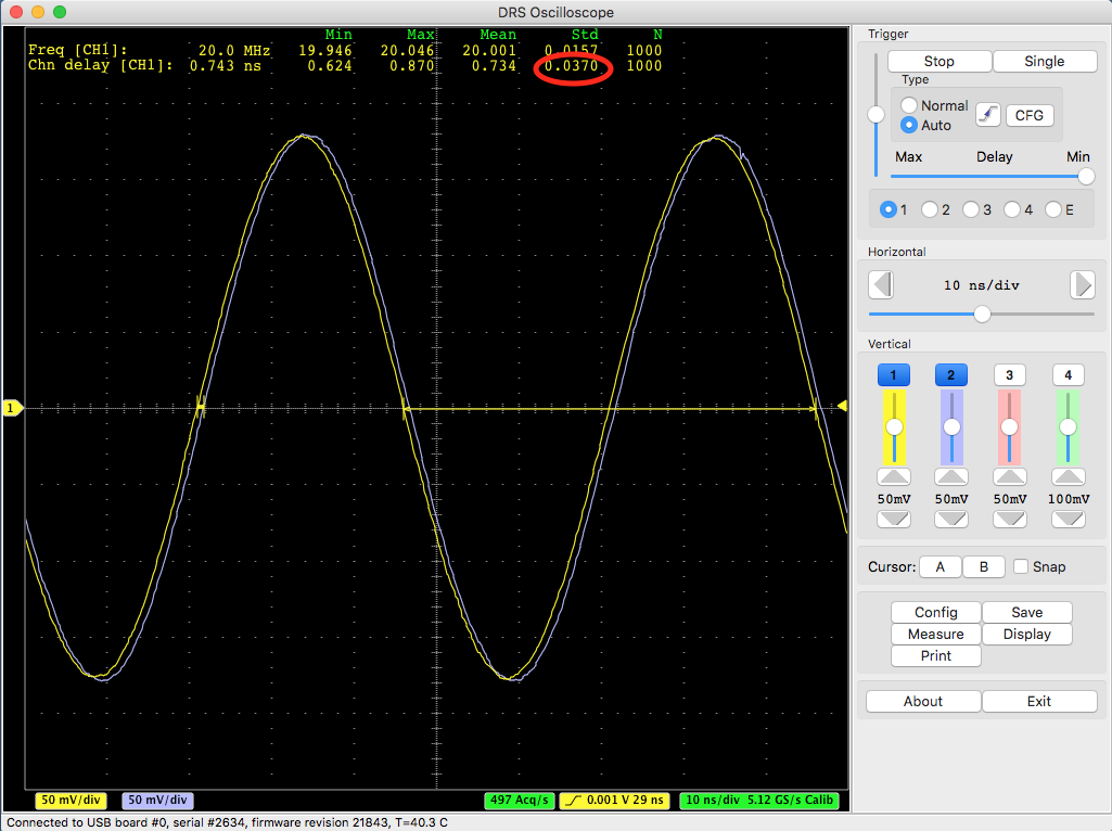
If I increase the frequency to 100 MHz and increase the amplitude, I get a better resolution:
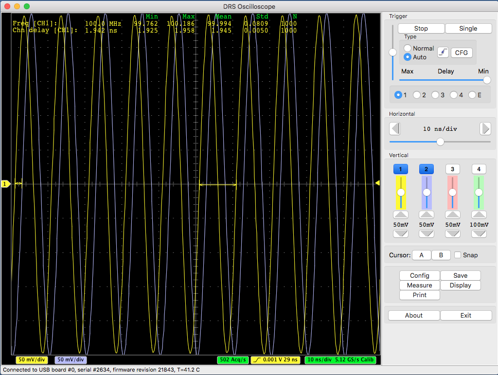
This is 5 ps which is better than 37 ps, but still not 2.5 ps. This can only be reached by sending single pulses to the evaluation board which have a rise time of > 300 mV / ns, which can be seen here:
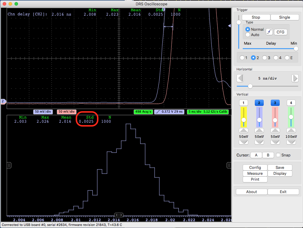
It is important to understand the relation timing - resolution vs. rise time / noise as explained in the quoted paper. If you have tiny pulses from your detector, you never will be able to measure excellent timing. This is physics, and not related to the specific electronics you are using.
Best regards,
Stefan
|
|
Tue Oct 11 09:04:33 2016, Danny Petschke, time difference between 2 channels only ~30-35ps @ 5GSmples/s
|
Hello Stefan,
thanks for the paper. That makes sense. I thought about sth. like that but wasn`t sure. Couldn´t check higher frequencies (limit of my function generator).
What do think about the other picture I attached yesterday where Chn1 shows a totally different offset than Chn2-4. Moreover Chn4 shows some streaks (red circle) ?
Best regards
Danny
| Stefan Ritt wrote: |
|
Ok, I got it. The timing resolution is affected by the signal-to-noise ratio over the rise-time of your signal. You find the full formula herer:
https://arxiv.org/abs/1405.4975
Your sine wave input signal has a slow rise time, and therefore limits the time resolution. I reproduced your measurement with a 20 MHz sine wave and got the same result:
If I increase the frequency to 100 MHz and increase the amplitude, I get a better resolution:
This is 5 ps which is better than 37 ps, but still not 2.5 ps. This can only be reached by sending single pulses to the evaluation board which have a rise time of > 300 mV / ns, which can be seen here:
It is important to understand the relation timing - resolution vs. rise time / noise as explained in the quoted paper. If you have tiny pulses from your detector, you never will be able to measure excellent timing. This is physics, and not related to the specific electronics you are using.
Best regards,
Stefan
|
|
|
Tue Oct 11 09:20:04 2016, Stefan Ritt, time difference between 2 channels only ~30-35ps @ 5GSmples/s
|
Concerning the offset, it looks to me like you moved the offset slider slider of channel 1 to a non-zero position. You see that from the marker at the very left side of the screen, where the yellow marker is at a different position as the others. Hint: a right-click on that slider sets it to zero. The little streak could be some kind of external noise.
| Danny Petschke wrote: |
|
Hello Stefan,
thanks for the paper. That makes sense. I thought about sth. like that but wasn`t sure. Couldn´t check higher frequencies (limit of my function generator).
What do think about the other picture I attached yesterday where Chn1 shows a totally different offset than Chn2-4. Moreover Chn4 shows some streaks (red circle) ?
Best regards
Danny
|
|
|
Tue Oct 11 22:11:26 2016, Stefan Ritt, time difference between 2 channels only ~30-35ps @ 5GSmples/s
|
Thank you very much! I will check it tomorrow!
-d
Concerning the offset, it looks to me like you moved the offset slider slider of channel 1 to a non-zero position. You see that from the marker at the very left side of the screen, where the yellow marker is at a different position as the others. Hint: a right-click on that slider sets it to zero. The little streak could be some kind of external noise.
| Danny Petschke wrote: |
|
Hello Stefan,
thanks for the paper. That makes sense. I thought about sth. like that but wasn`t sure. Couldn´t check higher frequencies (limit of my function generator).
What do think about the other picture I attached yesterday where Chn1 shows a totally different offset than Chn2-4. Moreover Chn4 shows some streaks (red circle) ?
Best regards
Danny
|
|
|
Wed Oct 26 21:15:35 2016, Alexey Lubinets, Problems with DRS command line
|
Hello, everybody
I have installed the software for the DRS4 Evaluation Board.
When I run the DRS Oscilloscope, it works OK (at least, my computer "knows", that the board is connected). But when I run the DRS Command Line Interface, it writes "USB successfully scanned, but no boards found
No DRS boards found".
How can I manage with this problem? The drivers for the DRS Evaluation Board are installed.
Regards, Alexey Lubinets |
|
Thu Oct 27 08:29:26 2016, Stefan Ritt, Problems with DRS command line
|
| Alexey Lubinets wrote: | Hello, everybody
I have installed the software for the DRS4 Evaluation Board.
When I run the DRS Oscilloscope, it works OK (at least, my computer "knows", that the board is connected). But when I run the DRS Command Line Interface, it writes "USB successfully scanned, but no boards found
No DRS boards found".
How can I manage with this problem? The drivers for the DRS Evaluation Board are installed.
Regards, Alexey Lubinets |
You are the first one describing this problem (out of ~200 people), so I guess the problem must be on your side. Have you made sure to start the DRS oscilloscope and the Command Line Interface not at the same time? Only one program can access the board at a given time. Have you tried disconnecting and re-connecting the board?
Stefan |
|
Fri Oct 28 15:02:18 2016, Simon Mendisch, Problems with DRS command line
|
| Stefan Ritt wrote: |
You are the first one describing this problem (out of ~200 people), so I guess the problem must be on your side. Have you made sure to start the DRS oscilloscope and the Command Line Interface not at the same time? Only one program can access the board at a given time. Have you tried disconnecting and re-connecting the board?
Stefan |
Hello,
that means, I am the second one experiencing this problem. To be more specific, the "No DRS Board found" problem is only present at one machine running Win7x64.
DRSOsc, of course not running simultaneously works just fine. Only drscl shows this behavior. Upgrading to a newer software version or a re-installation of the old one didn't solve the issue.
On other Win7x64 machines everything works fine, so I am pretty sure the problem is on this specific machine. Do you have any idea what could be the cause of this behavior?
Best Regards,
Simon |
|
Fri Oct 28 15:51:59 2016, Stefan Ritt, Problems with DRS command line
|
No, I absolutely have no idea. Both DRSOsc and drscl use exaclty the same code to access USB.
Stefan
| Simon Mendisch wrote: |
that means, I am the second one experiencing this problem. To be more specific, the "No DRS Board found" problem is only present at one machine running Win7x64.
DRSOsc, of course not running simultaneously works just fine. Only drscl shows this behavior. Upgrading to a newer software version or a re-installation of the old one didn't solve the issue.
On other Win7x64 machines everything works fine, so I am pretty sure the problem is on this specific machine. Do you have any idea what could be the cause of this behavior?
|
|
|
Fri Nov 4 17:41:03 2016, Christian Farina, Missing Header
|
Hello everybody,
I am completely new to this, so please bear with me.
I am trying to install the applications on my laptop. I downloaded and untar-ed the drivers and applications for Linux as described in the evaluation board manual. However, when I do the make, I get the following error:
drs-4.0.0$ make
g++ -g -O2 -Wall -Wuninitialized -fno-strict-aliasing -Iinclude -DOS_LINUX -DHAVE_LIBUSB -DUSE_DRS_MUTEX -c src/musbstd.c
In file included from src/musbstd.c:14:0:
include/musbstd.h:17:17: fatal error: usb.h: No such file or directory
#include <usb.h>
Can anybody help me please?
Thanks. |
|
Tue Nov 8 10:20:52 2016, Stefan Ritt, Missing Header
|
The web page from where you downloaded the software contains a sentence "requires libusb-1.0 package". Please install it. This package brings the "usb.h" header file.
Stefan
| Christian Farina wrote: |
|
Hello everybody,
I am completely new to this, so please bear with me.
I am trying to install the applications on my laptop. I downloaded and untar-ed the drivers and applications for Linux as described in the evaluation board manual. However, when I do the make, I get the following error:
drs-4.0.0$ make
g++ -g -O2 -Wall -Wuninitialized -fno-strict-aliasing -Iinclude -DOS_LINUX -DHAVE_LIBUSB -DUSE_DRS_MUTEX -c src/musbstd.c
In file included from src/musbstd.c:14:0:
include/musbstd.h:17:17: fatal error: usb.h: No such file or directory
#include <usb.h>
Can anybody help me please?
Thanks.
|
|
|
Wed Nov 9 17:19:48 2016, Christian Farina, Missing Header
|
Thank you Stefan, that was just what I needed.
Also, I have another question, if I am allowed to ask on this forum. I am trying to study how the time calibration of the DRS is done. Can you point me to the script in which this is done?
Thank you,
Christian
| Stefan Ritt wrote: |
|
The web page from where you downloaded the software contains a sentence "requires libusb-1.0 package". Please install it. This package brings the "usb.h" header file.
Stefan
| Christian Farina wrote: |
|
Hello everybody,
I am completely new to this, so please bear with me.
I am trying to install the applications on my laptop. I downloaded and untar-ed the drivers and applications for Linux as described in the evaluation board manual. However, when I do the make, I get the following error:
drs-4.0.0$ make
g++ -g -O2 -Wall -Wuninitialized -fno-strict-aliasing -Iinclude -DOS_LINUX -DHAVE_LIBUSB -DUSE_DRS_MUTEX -c src/musbstd.c
In file included from src/musbstd.c:14:0:
include/musbstd.h:17:17: fatal error: usb.h: No such file or directory
#include <usb.h>
Can anybody help me please?
Thanks.
|
|
|
|
Wed Nov 9 19:49:07 2016, Stefan Ritt, Missing Header
|
Best is to read this paper: https://arxiv.org/abs/1405.4975
The source code for that is in DRS.cpp in the DRS software distribution in the function DRSBoard::CalibrateTiming()
Stefan
| Christian Farina wrote: |
|
Thank you Stefan, that was just what I needed.
Also, I have another question, if I am allowed to ask on this forum. I am trying to study how the time calibration of the DRS is done. Can you point me to the script in which this is done?
Thank you,
Christian
| Stefan Ritt wrote: |
|
The web page from where you downloaded the software contains a sentence "requires libusb-1.0 package". Please install it. This package brings the "usb.h" header file.
Stefan
| Christian Farina wrote: |
|
Hello everybody,
I am completely new to this, so please bear with me.
I am trying to install the applications on my laptop. I downloaded and untar-ed the drivers and applications for Linux as described in the evaluation board manual. However, when I do the make, I get the following error:
drs-4.0.0$ make
g++ -g -O2 -Wall -Wuninitialized -fno-strict-aliasing -Iinclude -DOS_LINUX -DHAVE_LIBUSB -DUSE_DRS_MUTEX -c src/musbstd.c
In file included from src/musbstd.c:14:0:
include/musbstd.h:17:17: fatal error: usb.h: No such file or directory
#include <usb.h>
Can anybody help me please?
Thanks.
|
|
|
|
|
Thu Nov 10 20:54:45 2016, Christian Farina, Missing Header
|
Hi Stefan,
I have already read the paper. I was just unsure where the calibration code was located. Thank you so much for all your help.
Christian
| Stefan Ritt wrote: |
|
Best is to read this paper: https://arxiv.org/abs/1405.4975
The source code for that is in DRS.cpp in the DRS software distribution in the function DRSBoard::CalibrateTiming()
Stefan
| Christian Farina wrote: |
|
Thank you Stefan, that was just what I needed.
Also, I have another question, if I am allowed to ask on this forum. I am trying to study how the time calibration of the DRS is done. Can you point me to the script in which this is done?
Thank you,
Christian
| Stefan Ritt wrote: |
|
The web page from where you downloaded the software contains a sentence "requires libusb-1.0 package". Please install it. This package brings the "usb.h" header file.
Stefan
| Christian Farina wrote: |
|
Hello everybody,
I am completely new to this, so please bear with me.
I am trying to install the applications on my laptop. I downloaded and untar-ed the drivers and applications for Linux as described in the evaluation board manual. However, when I do the make, I get the following error:
drs-4.0.0$ make
g++ -g -O2 -Wall -Wuninitialized -fno-strict-aliasing -Iinclude -DOS_LINUX -DHAVE_LIBUSB -DUSE_DRS_MUTEX -c src/musbstd.c
In file included from src/musbstd.c:14:0:
include/musbstd.h:17:17: fatal error: usb.h: No such file or directory
#include <usb.h>
Can anybody help me please?
Thanks.
|
|
|
|
|
|
Thu Nov 10 04:41:24 2016, Abhishek Rajput, Break Statements in DRS4 Binary to ROOT Macro
|
Hello,
I recently modified the binary to ROOT convertor written by Stefan (https://midas.psi.ch/elogs/DRS4+Forum/361) so it can decode data taken with any channel or set of channels on the DRS4. In the process of testing this modifed version for data taken on all 4 channels, I encountered problems with decoding some of the event data. More specifically, upon hitting a certain event in some channel, the histograms for that channel would no longer be filled and the histograms for subsequent channels would not be filled with any event at all.
After considerable bug hunting, I discovered the source of this problem was due to the break statement in the following code extract from the ROOT to binary macro:
 for (n=0 ; n<5 ; n++) {
      // read event header
      i = fread(&eh, sizeof(eh), 1, f);
      if (i < 1)
         break;
For some events apparently, the event header fails to be read properly (fread line returns 0 in this case). Moreover, when I used the feof and ferror functions on a particular file I was testing, the feof function returned a value of 1.
So my questions deal with two scenarios.
Firstly, in the event of an fread error, is a break statement is necessary? Is it not possible to skip the voltage data for those events whose event header fails to be read properly? Or is it the case that when some "corrupted" event header is encountered, all waveform data subsequent to that event is likewise corrupted? If the former is the case, is it advisable to replace the break condition with an fseek line that advances the position indicator of the stream by an additional 2052*n_channels + 32 bytes (in accordance with the binary file specifications of page 25 on the DRS4 manual) so that the next set of voltage data can be read?
Secondly, in the case of an end of file error, does there exist any possible solution? Or is such an error an indication of a faulty drs4 channel or corrupted binary file?
Any help with the aforementioned issues would be greatly appreciated.
Abhishek
|
|
Thu Nov 10 09:56:04 2016, Stefan Ritt, Break Statements in DRS4 Binary to ROOT Macro
|
Hi,
fread() returns the number of bytes read and zero (I believe) if there is an end of file. So this break statement is a simple end-of-file test. There might be other erros such as hard disk failures, but these are extremely rare.
If course the file should not end in the middle of an event header. If it does, it means the file is corrupted and truncated, and we should not continue to read that file, that's why there is the break. The internal file is just a series of bytes, it does not know about the event header, so there will be no "error" if we have for example a missing event header but a voltage array. To be correct, the code should actually read
for (n=0 ; n<5 ; n++) {
      // read event header
      i = fread(&eh, sizeof(eh), 1, f);
      if (i < sizeof(eh))
         break;
Hope this helps,
Stefan
| Abhishek Rajput wrote: |
|
Hello,
I recently modified the binary to ROOT convertor written by Stefan (https://midas.psi.ch/elogs/DRS4+Forum/361) so it can decode data taken with any channel or set of channels on the DRS4. In the process of testing this modifed version for data taken on all 4 channels, I encountered problems with decoding some of the event data. More specifically, upon hitting a certain event in some channel, the histograms for that channel would no longer be filled and the histograms for subsequent channels would not be filled with any event at all.
After considerable bug hunting, I discovered the source of this problem was due to the break statement in the following code extract from the ROOT to binary macro:
 for (n=0 ; n<5 ; n++) {
      // read event header
      i = fread(&eh, sizeof(eh), 1, f);
      if (i < 1)
         break;
For some events apparently, the event header fails to be read properly (fread line returns 0 in this case). Moreover, when I used the feof and ferror functions on a particular file I was testing, the feof function returned a value of 1.
So my questions deal with two scenarios.
Firstly, in the event of an fread error, is a break statement is necessary? Is it not possible to skip the voltage data for those events whose event header fails to be read properly? Or is it the case that when some "corrupted" event header is encountered, all waveform data subsequent to that event is likewise corrupted? If the former is the case, is it advisable to replace the break condition with an fseek line that advances the position indicator of the stream by an additional 2052*n_channels + 32 bytes (in accordance with the binary file specifications of page 25 on the DRS4 manual) so that the next set of voltage data can be read?
Secondly, in the case of an end of file error, does there exist any possible solution? Or is such an error an indication of a faulty drs4 channel or corrupted binary file?
Any help with the aforementioned issues would be greatly appreciated.
Abhishek
|
|
|
Thu Nov 10 19:24:52 2016, Abhishek Rajput, Break Statements in DRS4 Binary to ROOT Macro
|
Hello,
I am wondering why the code should be changed to i < sizeof(eh), since doesn't fread(&eh,sizeof(eh),1,f) return 1 in this scenario? I've confirmed with a cout statement that this is the case, so this break condition will therefore always trigger as sizeof(eh) is 32 bytes.
Either way, I believe I figured out my problem. In my revised version of your code, I had two nested loops, the outer one being a loop over the channels and the inner one being a loop over the events. However, I really should have been doing the reverse considering the binary structure of the file. Otherwise, the end of the file will be reached for only a single iteration of the channel loop if I choose to loop through all the events in the data file.
Once I modified the code to have the outer loop be over all the events and the inner one be over all the channels, I no longer suffered from breaks in the loops.
Many thanks for your assistance.
Abhishek
| Stefan Ritt wrote: |
|
Hi,
fread() returns the number of bytes read and zero (I believe) if there is an end of file. So this break statement is a simple end-of-file test. There might be other erros such as hard disk failures, but these are extremely rare.
If course the file should not end in the middle of an event header. If it does, it means the file is corrupted and truncated, and we should not continue to read that file, that's why there is the break. The internal file is just a series of bytes, it does not know about the event header, so there will be no "error" if we have for example a missing event header but a voltage array. To be correct, the code should actually read
for (n=0 ; n<5 ; n++) {
      // read event header
      i = fread(&eh, sizeof(eh), 1, f);
      if (i < sizeof(eh))
         break;
Hope this helps,
Stefan
| Abhishek Rajput wrote: |
|
Hello,
I recently modified the binary to ROOT convertor written by Stefan (https://midas.psi.ch/elogs/DRS4+Forum/361) so it can decode data taken with any channel or set of channels on the DRS4. In the process of testing this modifed version for data taken on all 4 channels, I encountered problems with decoding some of the event data. More specifically, upon hitting a certain event in some channel, the histograms for that channel would no longer be filled and the histograms for subsequent channels would not be filled with any event at all.
After considerable bug hunting, I discovered the source of this problem was due to the break statement in the following code extract from the ROOT to binary macro:
 for (n=0 ; n<5 ; n++) {
      // read event header
      i = fread(&eh, sizeof(eh), 1, f);
      if (i < 1)
         break;
For some events apparently, the event header fails to be read properly (fread line returns 0 in this case). Moreover, when I used the feof and ferror functions on a particular file I was testing, the feof function returned a value of 1.
So my questions deal with two scenarios.
Firstly, in the event of an fread error, is a break statement is necessary? Is it not possible to skip the voltage data for those events whose event header fails to be read properly? Or is it the case that when some "corrupted" event header is encountered, all waveform data subsequent to that event is likewise corrupted? If the former is the case, is it advisable to replace the break condition with an fseek line that advances the position indicator of the stream by an additional 2052*n_channels + 32 bytes (in accordance with the binary file specifications of page 25 on the DRS4 manual) so that the next set of voltage data can be read?
Secondly, in the case of an end of file error, does there exist any possible solution? Or is such an error an indication of a faulty drs4 channel or corrupted binary file?
Any help with the aforementioned issues would be greatly appreciated.
Abhishek
|
|
|
|
Thu Nov 10 22:07:40 2016, Stefan Ritt, Break Statements in DRS4 Binary to ROOT Macro
|
You're right, fread() return the number of objects read, so indeed it should be one if successful.
| Abhishek Rajput wrote: |
|
Hello,
I am wondering why the code should be changed to i < sizeof(eh), since doesn't fread(&eh,sizeof(eh),1,f) return 1 in this scenario? I've confirmed with a cout statement that this is the case, so this break condition will therefore always trigger as sizeof(eh) is 32 bytes.
Either way, I believe I figured out my problem. In my revised version of your code, I had two nested loops, the outer one being a loop over the channels and the inner one being a loop over the events. However, I really should have been doing the reverse considering the binary structure of the file. Otherwise, the end of the file will be reached for only a single iteration of the channel loop if I choose to loop through all the events in the data file.
Once I modified the code to have the outer loop be over all the events and the inner one be over all the channels, I no longer suffered from breaks in the loops.
Many thanks for your assistance.
Abhishek
| Stefan Ritt wrote: |
|
Hi,
fread() returns the number of bytes read and zero (I believe) if there is an end of file. So this break statement is a simple end-of-file test. There might be other erros such as hard disk failures, but these are extremely rare.
If course the file should not end in the middle of an event header. If it does, it means the file is corrupted and truncated, and we should not continue to read that file, that's why there is the break. The internal file is just a series of bytes, it does not know about the event header, so there will be no "error" if we have for example a missing event header but a voltage array. To be correct, the code should actually read
for (n=0 ; n<5 ; n++) {
      // read event header
      i = fread(&eh, sizeof(eh), 1, f);
      if (i < sizeof(eh))
         break;
Hope this helps,
Stefan
| Abhishek Rajput wrote: |
|
Hello,
I recently modified the binary to ROOT convertor written by Stefan (https://midas.psi.ch/elogs/DRS4+Forum/361) so it can decode data taken with any channel or set of channels on the DRS4. In the process of testing this modifed version for data taken on all 4 channels, I encountered problems with decoding some of the event data. More specifically, upon hitting a certain event in some channel, the histograms for that channel would no longer be filled and the histograms for subsequent channels would not be filled with any event at all.
After considerable bug hunting, I discovered the source of this problem was due to the break statement in the following code extract from the ROOT to binary macro:
 for (n=0 ; n<5 ; n++) {
      // read event header
      i = fread(&eh, sizeof(eh), 1, f);
      if (i < 1)
         break;
For some events apparently, the event header fails to be read properly (fread line returns 0 in this case). Moreover, when I used the feof and ferror functions on a particular file I was testing, the feof function returned a value of 1.
So my questions deal with two scenarios.
Firstly, in the event of an fread error, is a break statement is necessary? Is it not possible to skip the voltage data for those events whose event header fails to be read properly? Or is it the case that when some "corrupted" event header is encountered, all waveform data subsequent to that event is likewise corrupted? If the former is the case, is it advisable to replace the break condition with an fseek line that advances the position indicator of the stream by an additional 2052*n_channels + 32 bytes (in accordance with the binary file specifications of page 25 on the DRS4 manual) so that the next set of voltage data can be read?
Secondly, in the case of an end of file error, does there exist any possible solution? Or is such an error an indication of a faulty drs4 channel or corrupted binary file?
Any help with the aforementioned issues would be greatly appreciated.
Abhishek
|
|
|
|
|
Wed Mar 9 09:57:20 2016, Christian D, LabView
|
Hi,
I would like to use the DRS4 board with LabView for fast readout.
Do you know anyone who has written a VI for that?
Thanks,
Christian |
|
Fri Nov 18 16:38:42 2016, Gerard Montarou, LabView
|
Hello,
Did you start to write some VI to interface DRS4board with labview ?
i also have in mind to do that.I am surprised that nobody alraedy did it since there is no answer toyour question
gerard
| Christian D wrote: |
|
Hi,
I would like to use the DRS4 board with LabView for fast readout.
Do you know anyone who has written a VI for that?
Thanks,
Christian
|
|
|
Fri Nov 18 05:52:45 2016, Kurtis Nishimura, Channel offsets in GetTime()
|
Hello,
I have a question about the GetTime() method in DRS.cpp. I understand how the DT values are applied for all channels, and I also understand from the evaluation board manual that the timing of each channel is synchronized at sample 0, so samples should really be aligned from channel-to-channel relative to sample 0.
However, DRS.cpp has the following snippet in DrsBoard::GetTime():
if (channelIndex > 0) {

      // correct all channels to channel 0 (Daniel's method)

      iend = tc >= 700 ? 700+1024 : 700;

      for (i=tc,gt0=0 ; i<iend ; i++)

         gt0 += fCellDT[chipIndex][0][i % 1024];


      for (i=tc,gt=0 ; i<iend ; i++)

         gt += fCellDT[chipIndex][channelIndex][i % 1024];


      for (i=0 ; i<fChannelDepth ; i++)

         time[i] += (float)(gt0 - gt);

   }
I can see what this is calculating and applying such an offset, but I don't understand why things seem to be referenced to sample 700. Is there a particular reason why sample 700 is chosen here? This does not seem like a straightforward application of the attached instructions from the evaluation board user's manual.
Any insight would be much appreciated!
Thanks so much,
-Kurtis |
|
Mon Nov 21 14:13:32 2016, Stefan Ritt, Channel offsets in GetTime()
|
Cell 700 is arbitrary. You can choose any cell to align the channels to each other. The only requirement is that it's always the same cell for each event. Historically, Daniel chose cell #700 more or less arbitrary, but later we found out that this works with any cell. So for the publication we went with cell #0 (and that's why we have t_ch,0 in the paper), but cell #700 was left in the code because of lazyness. Feel free to replace 700 with any other number and you should get the same result. In a newer version of the software I use
// align cell#0 of all channels

float t1 = time[0][(1024-tc) % 1024];

for (int ch=1 ; ch<8 ; ch++) {

   float t2 = time[ch][(1024-tc) % 1024];

   float dt = t1 - t2;
   for (int i=0 ; i<1024 ; i++)

      time[ch][i] += dt;

   }
which is also a bit simpler. So time[ch] contains already the integrated time array (like 0.2 ns, 0.4 ns, 0.6 ns if at 5 GSPS, not the delta_t values as in the DRS.cpp code). Since the readout starts with cell # tc, the cell time[channel][1024-tc] is the physical cell #0 of the chip. The code makes sure that cell #0 in all 8 channels has the same time value.
Best regards,
Stefan
| Kurtis Nishimura wrote: |
|
Hello,
I have a question about the GetTime() method in DRS.cpp. I understand how the DT values are applied for all channels, and I also understand from the evaluation board manual that the timing of each channel is synchronized at sample 0, so samples should really be aligned from channel-to-channel relative to sample 0.
However, DRS.cpp has the following snippet in DrsBoard::GetTime():
if (channelIndex > 0) {

			      // correct all channels to channel 0 (Daniel's method)

			      iend = tc >= 700 ? 700+1024 : 700;

			      for (i=tc,gt0=0 ; i<iend ; i++)

			         gt0 += fCellDT[chipIndex][0][i % 1024];


			      for (i=tc,gt=0 ; i<iend ; i++)

			         gt += fCellDT[chipIndex][channelIndex][i % 1024];


			      for (i=0 ; i<fChannelDepth ; i++)

			         time[i] += (float)(gt0 - gt);

			   }
I can see what this is calculating and applying such an offset, but I don't understand why things seem to be referenced to sample 700. Is there a particular reason why sample 700 is chosen here? This does not seem like a straightforward application of the attached instructions from the evaluation board user's manual.
Any insight would be much appreciated!
Thanks so much,
-Kurtis
|
|
|
Thu Nov 24 00:40:38 2016, Alexey Lubinets, PLL did not lock
|
Hello, everybody!
I installed DRSosc and DRScl. Command line works normally (at least, it can "see" the board). But when I start the oscilloscope, I have an error: "PLLs did not lock on USB board #0, serial number #...". In Info section I can see the board type = 9 (and in the error message I have "USB board #0").
After that I have a warning: "Board on USB0 has invalid voltge calibration. Only raw data will be displayed". I tried to execute voltage calibration using DRSosc and DRScl, but it did not help.
Did anybody face such broblems? Does anybody know, how to fix them?
Thank you. Alexey. |
|
Thu Nov 24 08:13:23 2016, Stefan Ritt, PLL did not lock
|
Which serial number has the board? Has it been in use before or is it a new board?
Stefan
| Alexey Lubinets wrote: |
|
Hello, everybody!
I installed DRSosc and DRScl. Command line works normally (at least, it can "see" the board). But when I start the oscilloscope, I have an error: "PLLs did not lock on USB board #0, serial number #...". In Info section I can see the board type = 9 (and in the error message I have "USB board #0").
After that I have a warning: "Board on USB0 has invalid voltge calibration. Only raw data will be displayed". I tried to execute voltage calibration using DRSosc and DRScl, but it did not help.
Did anybody face such broblems? Does anybody know, how to fix them?
Thank you. Alexey.
|
|
|
Mon Nov 28 16:48:15 2016, Alexey Lubinets, PLL did not lock
|
The serial number is 2586. This board is about two years old, and it might be in use (but I do not know exactly).
| Stefan Ritt wrote: |
|
Which serial number has the board? Has it been in use before or is it a new board?
Stefan
| Alexey Lubinets wrote: |
|
Hello, everybody!
I installed DRSosc and DRScl. Command line works normally (at least, it can "see" the board). But when I start the oscilloscope, I have an error: "PLLs did not lock on USB board #0, serial number #...". In Info section I can see the board type = 9 (and in the error message I have "USB board #0").
After that I have a warning: "Board on USB0 has invalid voltge calibration. Only raw data will be displayed". I tried to execute voltage calibration using DRSosc and DRScl, but it did not help.
Did anybody face such broblems? Does anybody know, how to fix them?
Thank you. Alexey.
|
|
|
|
Mon Nov 28 16:52:38 2016, Stefan Ritt, PLL did not lock
|
Have you tried to unplug and re-plug the board a few times? According to our database, you should have three boards. Do all three show the same behavior or only this board? In case all three show this, it could be a hint of a software problem. If two boards are good and one is bad, this would be a hint of a hardware problem (broken board).
Stefan
| Alexey Lubinets wrote: |
|
The serial number is 2586. This board is about two years old, and it might be in use (but I do not know exactly).
| Stefan Ritt wrote: |
|
Which serial number has the board? Has it been in use before or is it a new board?
Stefan
| Alexey Lubinets wrote: |
|
Hello, everybody!
I installed DRSosc and DRScl. Command line works normally (at least, it can "see" the board). But when I start the oscilloscope, I have an error: "PLLs did not lock on USB board #0, serial number #...". In Info section I can see the board type = 9 (and in the error message I have "USB board #0").
After that I have a warning: "Board on USB0 has invalid voltge calibration. Only raw data will be displayed". I tried to execute voltage calibration using DRSosc and DRScl, but it did not help.
Did anybody face such broblems? Does anybody know, how to fix them?
Thank you. Alexey.
|
|
|
|
|