 Tue Aug 28 17:52:45 2012, Zach Miller, DRS-4.0.0 DOScreen.cpp Tue Aug 28 17:52:45 2012, Zach Miller, DRS-4.0.0 DOScreen.cpp
|
Hi,
I found an old thread regarding a fix for DOScreen.cpp for DRS-3.1.0, that fixes an "ambiguous overload problem." Currently when I attempt to build the drs-4.0.0, I get this similar error:
src/DOScreen.cpp:332:39: error: call of overloaded ‘Append(int)’ is ambiguous
This section of code is different than what the previous thread was correcting, and though I attempted to apply the logic of the old thread, I haven't fixed this yet.
The following is the code for that section:
-----
329 for (int i=0 ; i<5 ; i++)
330 if (tc & (1<<(i+8))) {
331 if (i < 4)
332 wxst1.Append(wxT('1'+i));
333 else
334 wxst1.Append(wxT('E'));
335 wxst1.Append(wxT('&'));
336 }
337 if (wxst1.Length() > 0)
338 wxst1 = wxst1.Left(wxst1.Length()-1);
339 wxst1.Append(wxT(')'));
------
I've attempted a few fixes, but unfortunately, my understanding of the code is not great, and I haven't managed to fix this yet. Any help would be appreciated.
Thanks,
Zach Miller |
 Wed Aug 29 10:52:44 2012, Stefan Ritt, DRS-4.0.0 DOScreen.cpp Wed Aug 29 10:52:44 2012, Stefan Ritt, DRS-4.0.0 DOScreen.cpp
|
| Zach Miller wrote: |
|
Hi,
I found an old thread regarding a fix for DOScreen.cpp for DRS-3.1.0, that fixes an "ambiguous overload problem." Currently when I attempt to build the drs-4.0.0, I get this similar error:
src/DOScreen.cpp:332:39: error: call of overloaded ‘Append(int)’ is ambiguous
This section of code is different than what the previous thread was correcting, and though I attempted to apply the logic of the old thread, I haven't fixed this yet.
The following is the code for that section:
-----
329 for (int i=0 ; i<5 ; i++)
330 if (tc & (1<<(i+8))) {
331 if (i < 4)
332 wxst1.Append(wxT('1'+i));
333 else
334 wxst1.Append(wxT('E'));
335 wxst1.Append(wxT('&'));
336 }
337 if (wxst1.Length() > 0)
338 wxst1 = wxst1.Left(wxst1.Length()-1);
339 wxst1.Append(wxT(')'));
------
I've attempted a few fixes, but unfortunately, my understanding of the code is not great, and I haven't managed to fix this yet. Any help would be appreciated.
Thanks,
Zach Miller
|
Just put (char) in front of wxT(...), like
if (tc > 0) {
wxString wxst1, wxst2;
wxst1.Append((char)wxT('('));
for (int i=0 ; i<5 ; i++)
if (tc & (1<<i)) {
if (i < 4)
wxst1.Append((char) (wxT('1'+i)));
else
wxst1.Append((char) wxT('E'));
wxst1.Append((char) wxT('|'));
}
for (int i=0 ; i<5 ; i++)
if (tc & (1<<(i+8))) {
if (i < 4)
wxst1.Append((char) (wxT('1'+i)));
else
wxst1.Append((char) wxT('E'));
wxst1.Append((char) wxT('&'));
}
if (wxst1.Length() > 0)
wxst1 = wxst1.Left(wxst1.Length()-1);
wxst1.Append((char) wxT(')'));
|
|
Wed Aug 29 16:42:42 2012, Zach Miller, DRS-4.0.0 DOScreen.cpp
|
| Stefan Ritt wrote: |
|
| Zach Miller wrote: |
|
Hi,
I found an old thread regarding a fix for DOScreen.cpp for DRS-3.1.0, that fixes an "ambiguous overload problem." Currently when I attempt to build the drs-4.0.0, I get this similar error:
src/DOScreen.cpp:332:39: error: call of overloaded ‘Append(int)’ is ambiguous
This section of code is different than what the previous thread was correcting, and though I attempted to apply the logic of the old thread, I haven't fixed this yet.
The following is the code for that section:
-----
329 for (int i=0 ; i<5 ; i++)
330 if (tc & (1<<(i+8))) {
331 if (i < 4)
332 wxst1.Append(wxT('1'+i));
333 else
334 wxst1.Append(wxT('E'));
335 wxst1.Append(wxT('&'));
336 }
337 if (wxst1.Length() > 0)
338 wxst1 = wxst1.Left(wxst1.Length()-1);
339 wxst1.Append(wxT(')'));
------
I've attempted a few fixes, but unfortunately, my understanding of the code is not great, and I haven't managed to fix this yet. Any help would be appreciated.
Thanks,
Zach Miller
|
Just put (char) in front of wxT(...), like
if (tc > 0) {
wxString wxst1, wxst2;
wxst1.Append((char)wxT('('));
for (int i=0 ; i<5 ; i++)
if (tc & (1<<i)) {
if (i < 4)
wxst1.Append((char) (wxT('1'+i)));
else
wxst1.Append((char) wxT('E'));
wxst1.Append((char) wxT('|'));
}
for (int i=0 ; i<5 ; i++)
if (tc & (1<<(i+8))) {
if (i < 4)
wxst1.Append((char) (wxT('1'+i)));
else
wxst1.Append((char) wxT('E'));
wxst1.Append((char) wxT('&'));
}
if (wxst1.Length() > 0)
wxst1 = wxst1.Left(wxst1.Length()-1);
wxst1.Append((char) wxT(')'));
|
Hi Stefan,
Thanks for the response. I have tried that and it fixes all the lines except the ones that have:
wxst1.Append((char) (wxT('1'+i)));
Those lines still don't compile for me. I've also tried: wxst1.Append((char) (wxT('1'+(char)i))); and wxst1.Append((char) (wxT((char)'1'+i))); as well as a few other combinations of (char) and Append.
I get the same error of: "Call of overloaded "Append(int)" is ambiguous."
Any other help would be greatly appreciated. Thanks!
-Zach |
|
Wed Aug 29 16:45:36 2012, Stefan Ritt, DRS-4.0.0 DOScreen.cpp
|
| Zach Miller wrote: |
|
| Stefan Ritt wrote: |
|
| Zach Miller wrote: |
|
Hi,
I found an old thread regarding a fix for DOScreen.cpp for DRS-3.1.0, that fixes an "ambiguous overload problem." Currently when I attempt to build the drs-4.0.0, I get this similar error:
src/DOScreen.cpp:332:39: error: call of overloaded ‘Append(int)’ is ambiguous
This section of code is different than what the previous thread was correcting, and though I attempted to apply the logic of the old thread, I haven't fixed this yet.
The following is the code for that section:
-----
329 for (int i=0 ; i<5 ; i++)
330 if (tc & (1<<(i+8))) {
331 if (i < 4)
332 wxst1.Append(wxT('1'+i));
333 else
334 wxst1.Append(wxT('E'));
335 wxst1.Append(wxT('&'));
336 }
337 if (wxst1.Length() > 0)
338 wxst1 = wxst1.Left(wxst1.Length()-1);
339 wxst1.Append(wxT(')'));
------
I've attempted a few fixes, but unfortunately, my understanding of the code is not great, and I haven't managed to fix this yet. Any help would be appreciated.
Thanks,
Zach Miller
|
Just put (char) in front of wxT(...), like
if (tc > 0) {
wxString wxst1, wxst2;
wxst1.Append((char)wxT('('));
for (int i=0 ; i<5 ; i++)
if (tc & (1<<i)) {
if (i < 4)
wxst1.Append((char) (wxT('1'+i)));
else
wxst1.Append((char) wxT('E'));
wxst1.Append((char) wxT('|'));
}
for (int i=0 ; i<5 ; i++)
if (tc & (1<<(i+8))) {
if (i < 4)
wxst1.Append((char) (wxT('1'+i)));
else
wxst1.Append((char) wxT('E'));
wxst1.Append((char) wxT('&'));
}
if (wxst1.Length() > 0)
wxst1 = wxst1.Left(wxst1.Length()-1);
wxst1.Append((char) wxT(')'));
|
Hi Stefan,
Thanks for the response. I have tried that and it fixes all the lines except the ones that have:
wxst1.Append((char) (wxT('1'+i)));
Those lines still don't compile for me. I've also tried: wxst1.Append((char) (wxT('1'+(char)i))); and wxst1.Append((char) (wxT((char)'1'+i))); as well as a few other combinations of (char) and Append.
I get the same error of: "Call of overloaded "Append(int)" is ambiguous."
Any other help would be greatly appreciated. Thanks!
-Zach
|
wxst1.Append((char) (wxT((char)('1'+i)))); maybe ??? |
|
Wed Aug 29 16:57:49 2012, Zach Miller, DRS-4.0.0 DOScreen.cpp
|
| Stefan Ritt wrote: |
|
| Zach Miller wrote: |
|
| Stefan Ritt wrote: |
|
| Zach Miller wrote: |
|
Hi,
I found an old thread regarding a fix for DOScreen.cpp for DRS-3.1.0, that fixes an "ambiguous overload problem." Currently when I attempt to build the drs-4.0.0, I get this similar error:
src/DOScreen.cpp:332:39: error: call of overloaded ‘Append(int)’ is ambiguous
This section of code is different than what the previous thread was correcting, and though I attempted to apply the logic of the old thread, I haven't fixed this yet.
The following is the code for that section:
-----
329 for (int i=0 ; i<5 ; i++)
330 if (tc & (1<<(i+8))) {
331 if (i < 4)
332 wxst1.Append(wxT('1'+i));
333 else
334 wxst1.Append(wxT('E'));
335 wxst1.Append(wxT('&'));
336 }
337 if (wxst1.Length() > 0)
338 wxst1 = wxst1.Left(wxst1.Length()-1);
339 wxst1.Append(wxT(')'));
------
I've attempted a few fixes, but unfortunately, my understanding of the code is not great, and I haven't managed to fix this yet. Any help would be appreciated.
Thanks,
Zach Miller
|
Just put (char) in front of wxT(...), like
if (tc > 0) {
wxString wxst1, wxst2;
wxst1.Append((char)wxT('('));
for (int i=0 ; i<5 ; i++)
if (tc & (1<<i)) {
if (i < 4)
wxst1.Append((char) (wxT('1'+i)));
else
wxst1.Append((char) wxT('E'));
wxst1.Append((char) wxT('|'));
}
for (int i=0 ; i<5 ; i++)
if (tc & (1<<(i+8))) {
if (i < 4)
wxst1.Append((char) (wxT('1'+i)));
else
wxst1.Append((char) wxT('E'));
wxst1.Append((char) wxT('&'));
}
if (wxst1.Length() > 0)
wxst1 = wxst1.Left(wxst1.Length()-1);
wxst1.Append((char) wxT(')'));
|
Hi Stefan,
Thanks for the response. I have tried that and it fixes all the lines except the ones that have:
wxst1.Append((char) (wxT('1'+i)));
Those lines still don't compile for me. I've also tried: wxst1.Append((char) (wxT('1'+(char)i))); and wxst1.Append((char) (wxT((char)'1'+i))); as well as a few other combinations of (char) and Append.
I get the same error of: "Call of overloaded "Append(int)" is ambiguous."
Any other help would be greatly appreciated. Thanks!
-Zach
|
wxst1.Append((char) (wxT((char)('1'+i)))); maybe ???
|
Aha!
wxst1.Append((char) (wxT('1'+i)));
That one actually works as you initially thought, but you my editor was being picky of (char)wxt... instead of (char) (wxt....). For some reason, it has to have the extra set of parentheses around wxt(). Thank You! |
|
Thu Oct 4 20:50:36 2012, Zach Miller, DRS5
|
Hi,
Our group had previously heard that a "DRS-5.0" might be on the horizon and that it may have ethernet capabilities as well as 16-input channels (we heard this when ordering the DRS-4). Is this still in the works and accurate information? If so, is there a rough estimate to the "release date?"
Thanks for your time,
Zach Miller |
|
Thu Oct 4 20:59:18 2012, Stefan Ritt, DRS5
|
| Zach Miller wrote: |
|
Hi,
Our group had previously heard that a "DRS-5.0" might be on the horizon and that it may have ethernet capabilities as well as 16-input channels (we heard this when ordering the DRS-4). Is this still in the works and accurate information? If so, is there a rough estimate to the "release date?"
Thanks for your time,
Zach Miller
|
You mix up two things: The DRS5 chip is a new device with improved samling speed (10 GSPS) and lower dead time. This chip might come in 2-3 years. The 16-input board you mentioned is a DAQ board based on the DRS4 chip. This board well be operational beginning of 2013 as a prototype. It is not clear however at this point in which way this board will be made available for public. Maybe we will license this to industry. The design is however pretty much defined: 16 channels with gain 0.1-100, 1 GHz Bandwidth, Gigabit Ethernet output, and multi-board capabilities. Trigger on each channel with logical combinations. 80 MSPS continuous sampling (in addition to the DRS4 sampling). Each channel can be biased 0-210 V for SiPMT or APD power. A 19" 3 HE crate will host 16 boards with 256 channels.
/Stefan |
|
Thu Oct 4 21:07:27 2012, Zach Miller, DRS5
|
| Stefan Ritt wrote: |
|
| Zach Miller wrote: |
|
Hi,
Our group had previously heard that a "DRS-5.0" might be on the horizon and that it may have ethernet capabilities as well as 16-input channels (we heard this when ordering the DRS-4). Is this still in the works and accurate information? If so, is there a rough estimate to the "release date?"
Thanks for your time,
Zach Miller
|
You mix up two things: The DRS5 chip is a new device with improved samling speed (10 GSPS) and lower dead time. This chip might come in 2-3 years. The 16-input board you mentioned is a DAQ board based on the DRS4 chip. This board well be operational beginning of 2013 as a prototype. It is not clear however at this point in which way this board will be made available for public. Maybe we will license this to industry. The design is however pretty much defined: 16 channels with gain 0.1-100, 1 GHz Bandwidth, Gigabit Ethernet output, and multi-board capabilities. Trigger on each channel with logical combinations. 80 MSPS continuous sampling (in addition to the DRS4 sampling). Each channel can be biased 0-210 V for SiPMT or APD power. A 19" 3 HE crate will host 16 boards with 256 channels.
/Stefan
|
Thanks, Stefan. That was the information we were looking for.
Cheers.
-Zach |
|
Fri Oct 12 14:06:04 2012, Moritz von Witzleben, DRS abbreviation
|
Hello,
what is the abbreviation of DRS?
Thanks and kind Regards,
Moritz |
|
Fri Oct 12 14:09:37 2012, Stefan Ritt, DRS abbreviation
|
| Moritz von Witzleben wrote: |
|
Hello,
what is the abbreviation of DRS?
Thanks and kind Regards,
Moritz
|
Domino Ring Sampler. |
|
Thu Nov 1 20:08:33 2012, hongwei yang, DRS4 firmware
|
Hi,
We are using drs4 board, but oscilloscope app will somehow stop to work if we config trigger into "or and", When I look into the drs4 firmware file drs4_eval3_app.vhd, I couldn't find the trigger_config value assignment which is mentioned at(#7 offset 0x1E from 31 downto 16) in manual_version 4.
could you help me find this trigger_config access point? Or is there any drs4_eval4_app.vhd missing in the source files?
thanks
Hongwei |
Thu Nov 1 20:17:42 2012, Stefan Ritt, DRS4 firmware 
|
| hongwei yang wrote: |
|
Hi,
We are using drs4 board, but oscilloscope app will somehow stop to work if we config trigger into "or and", When I look into the drs4 firmware file drs4_eval3_app.vhd, I couldn't find the trigger_config value assignment which is mentioned at(#7 offset 0x1E from 31 downto 16) in manual_version 4.
could you help me find this trigger_config access point?
thanks
Hongwei
|
The "and" in the trigger section means now "coincidence". So the V4 board can trigger on a coincidence between two or more channels. If there is no pulse at the same time on the coincidence channels, the board will of course not trigger. The according firmware was introduced in V4, so please look at drs4_eval4_app.vhd (not eval3).
I just realized that the V4 firmware might be missing in the distribution, so I have attached it here. Look for drs_ctl_trigger_config.
Best regards,
Stefan |
|
Thu Nov 1 20:21:44 2012, hongwei yang, DRS4 firmware
|
| Stefan Ritt wrote: |
|
| hongwei yang wrote: |
|
Hi,
We are using drs4 board, but oscilloscope app will somehow stop to work if we config trigger into "or and", When I look into the drs4 firmware file drs4_eval3_app.vhd, I couldn't find the trigger_config value assignment which is mentioned at(#7 offset 0x1E from 31 downto 16) in manual_version 4.
could you help me find this trigger_config access point?
thanks
Hongwei
|
The "and" in the trigger section means now "coincidence". So the V4 board can trigger on a coincidence between two or more channels. If there is no pulse at the same time on the coincidence channels, the board will of course not trigger. The according firmware was introduced in V4, so please look at drs4_eval4_app.vhd (not eval3).
I just realized that the V4 firmware might be missing in the distribution, so I have attached it here. Look for drs_ctl_trigger_config.
Best regards,
Stefan
|
Ah, great, that helps, Thank you!
Hongwei |
|
Thu Nov 1 20:25:53 2012, hongwei yang, DRS4 firmware
|
| hongwei yang wrote: |
|
| Stefan Ritt wrote: |
|
| hongwei yang wrote: |
|
Hi,
We are using drs4 board, but oscilloscope app will somehow stop to work if we config trigger into "or and", When I look into the drs4 firmware file drs4_eval3_app.vhd, I couldn't find the trigger_config value assignment which is mentioned at(#7 offset 0x1E from 31 downto 16) in manual_version 4.
could you help me find this trigger_config access point?
thanks
Hongwei
|
The "and" in the trigger section means now "coincidence". So the V4 board can trigger on a coincidence between two or more channels. If there is no pulse at the same time on the coincidence channels, the board will of course not trigger. The according firmware was introduced in V4, so please look at drs4_eval4_app.vhd (not eval3).
I just realized that the V4 firmware might be missing in the distribution, so I have attached it here. Look for drs_ctl_trigger_config.
Best regards,
Stefan
|
Ah, great, that helps, Thank you!
Hongwei
|
By the way, will there be a drs4_eval4.vhd as well? |
|
Thu Nov 1 20:32:03 2012, Stefan Ritt, DRS4 firmware
|
| hongwei yang wrote: |
|
| hongwei yang wrote: |
|
| Stefan Ritt wrote: |
|
| hongwei yang wrote: |
|
Hi,
We are using drs4 board, but oscilloscope app will somehow stop to work if we config trigger into "or and", When I look into the drs4 firmware file drs4_eval3_app.vhd, I couldn't find the trigger_config value assignment which is mentioned at(#7 offset 0x1E from 31 downto 16) in manual_version 4.
could you help me find this trigger_config access point?
thanks
Hongwei
|
The "and" in the trigger section means now "coincidence". So the V4 board can trigger on a coincidence between two or more channels. If there is no pulse at the same time on the coincidence channels, the board will of course not trigger. The according firmware was introduced in V4, so please look at drs4_eval4_app.vhd (not eval3).
I just realized that the V4 firmware might be missing in the distribution, so I have attached it here. Look for drs_ctl_trigger_config.
Best regards,
Stefan
|
Ah, great, that helps, Thank you!
Hongwei
|
By the way, will there be a drs4_eval4.vhd as well?
|
Here it is. |
|
Thu Nov 1 20:46:53 2012, hongwei yang, DRS4 firmware
|
| Stefan Ritt wrote: |
|
| hongwei yang wrote: |
|
| hongwei yang wrote: |
|
| Stefan Ritt wrote: |
|
| hongwei yang wrote: |
|
Hi,
We are using drs4 board, but oscilloscope app will somehow stop to work if we config trigger into "or and", When I look into the drs4 firmware file drs4_eval3_app.vhd, I couldn't find the trigger_config value assignment which is mentioned at(#7 offset 0x1E from 31 downto 16) in manual_version 4.
could you help me find this trigger_config access point?
thanks
Hongwei
|
The "and" in the trigger section means now "coincidence". So the V4 board can trigger on a coincidence between two or more channels. If there is no pulse at the same time on the coincidence channels, the board will of course not trigger. The according firmware was introduced in V4, so please look at drs4_eval4_app.vhd (not eval3).
I just realized that the V4 firmware might be missing in the distribution, so I have attached it here. Look for drs_ctl_trigger_config.
Best regards,
Stefan
|
Ah, great, that helps, Thank you!
Hongwei
|
By the way, will there be a drs4_eval4.vhd as well?
|
Here it is.
|
Thanks. have a good day |
|
Mon Oct 29 18:30:28 2012, Martin Petriska, GetWave
|
I have some question according to GetWave function. In drs_exam.cpp simple GetWave(0,0,wave_array[]) etc...is used. Is there primary (cell) calibration, secondary calibration (Readout) and remove Spikes used, as in DRS Oscilloscope application? |
|
Tue Nov 13 11:26:32 2012, Stefan Ritt, GetWave
|
| Martin Petriska wrote: |
|
I have some question according to GetWave function. In drs_exam.cpp simple GetWave(0,0,wave_array[]) etc...is used. Is there primary (cell) calibration, secondary calibration (Readout) and remove Spikes used, as in DRS Oscilloscope application?
|
Yes, yes, no. To get spike removals, you need the function RemoveSpikes from Osci.cpp in the DRSOsc project. |
|
Wed Nov 21 08:34:52 2012, Gyuhee Kim, Question for using Multi board
|
Hi.
I have 2 DRS4 evaluation V4 boards, and I want to use these 2 board to multi board DAQ system for 4 ch vs 4 ch DAQ.
But there is no option for multi board use. I just only find the multi board trigger mode check button on DRS4 Oscilloscope program, but I couldn`t check.
Is there any method to use multi board?
Best regards.
Gyuhee. |
|
Wed Nov 21 08:38:26 2012, Stefan Ritt, Question for using Multi board
|
| Gyuhee Kim wrote: |
|
Hi.
I have 2 DRS4 evaluation V4 boards, and I want to use these 2 board to multi board DAQ system for 4 ch vs 4 ch DAQ.
But there is no option for multi board use. I just only find the multi board trigger mode check button on DRS4 Oscilloscope program, but I couldn`t check.
Is there any method to use multi board?
Best regards.
Gyuhee.
|
This mode is not yet implemented in firmware. Maybe I find some time towards the end of this year to add this. At the moment, you have to build and external trigger to synchronize the two boards. There are also 16-channel boards on the market where you would not need a multi-board mode. Just Google for "DT5742".
/Stefan |
|
Wed Nov 21 08:48:00 2012, Gyuhee Kim, Question for using Multi board
|
| Stefan Ritt wrote: |
|
| Gyuhee Kim wrote: |
|
Hi.
I have 2 DRS4 evaluation V4 boards, and I want to use these 2 board to multi board DAQ system for 4 ch vs 4 ch DAQ.
But there is no option for multi board use. I just only find the multi board trigger mode check button on DRS4 Oscilloscope program, but I couldn`t check.
Is there any method to use multi board?
Best regards.
Gyuhee.
|
This mode is not yet implemented in firmware. Maybe I find some time towards the end of this year to add this. At the moment, you have to build and external trigger to synchronize the two boards. There are also 16-channel boards on the market where you would not need a multi-board mode. Just Google for "DT5742".
/Stefan
|
Thanks Stefan.
I will build external trigger system. |
|
Wed Nov 28 16:54:46 2012, Stefan Ritt, DRS Oscilloscope for Raspberry Pi and Mac OSX 10.8
|
I made a pre-compiled package for Mac OSX 10.8 (Mountain Lion), so one should be able to install the DRS Oscilloscope software with one mouse click on a recent Mac.
The Makefile in the tar ball now also supports OSX 10.8, so one could even compile it from the sources on a Mac, after libusb-1.0 and wxWidgets have been installed. That might then also work on older versions of OSX.
In addition, the software has been adaptes so that it compiles nicely on a Raspberry Pi (http://www.raspberrypi.org), a screenshot has been attached. Together with a Raspberry Pi and an old screen, the evaluation board is one of the cheapest available oscilloscopes.
|
|
Mon Dec 3 08:32:28 2012, Gyuhee Kim, Another question about using multi boards.
|
Hi.
I asked about using multi boards some days ago, and I got answer to use external trigger. (Thanks Stefan!)
And here is another question. I made two external triggers and try to acquire coincidence data using two boards. but DRS Oscilloscope program can connect only one board and don`t acquire both of them simultaneously.
So I tried to use two computer for each board separately, but, well, you already know, I failed to acquire because two computers don`t promise to synchronize the two boards acquisition.
Is there any method to solve this problem?
1. I want to acquire coincidence data from the two DRS 4 Evaluation board V4 simultaneosly.
2. I have external trigger to provide the two boards at the same time.
3. How can I get data from the two boards?
Best regards.
Gyuhee. |
|
Mon Dec 3 09:18:09 2012, Stefan Ritt, Another question about using multi boards.
|
| Gyuhee Kim wrote: |
|
Hi.
I asked about using multi boards some days ago, and I got answer to use external trigger. (Thanks Stefan!)
And here is another question. I made two external triggers and try to acquire coincidence data using two boards. but DRS Oscilloscope program can connect only one board and don`t acquire both of them simultaneously.
So I tried to use two computer for each board separately, but, well, you already know, I failed to acquire because two computers don`t promise to synchronize the two boards acquisition.
Is there any method to solve this problem?
1. I want to acquire coincidence data from the two DRS 4 Evaluation board V4 simultaneosly.
2. I have external trigger to provide the two boards at the same time.
3. How can I get data from the two boards?
Best regards.
Gyuhee.
|
You have to write your own program. DRS Oscilloscope does not (yet) support this. Take drs_exam.cpp as a starting point and try to extend it to two boards. One tricky point is that the external trigger may only fire AFTER the two boards have been read out. So you need some means of re-enabling the external trigger after you read out both boards.
Stefan |
|
Mon Dec 3 11:40:35 2012, Gyuhee Kim, Another question about using multi boards.
|
| Stefan Ritt wrote: |
|
| Gyuhee Kim wrote: |
|
Hi.
I asked about using multi boards some days ago, and I got answer to use external trigger. (Thanks Stefan!)
And here is another question. I made two external triggers and try to acquire coincidence data using two boards. but DRS Oscilloscope program can connect only one board and don`t acquire both of them simultaneously.
So I tried to use two computer for each board separately, but, well, you already know, I failed to acquire because two computers don`t promise to synchronize the two boards acquisition.
Is there any method to solve this problem?
1. I want to acquire coincidence data from the two DRS 4 Evaluation board V4 simultaneosly.
2. I have external trigger to provide the two boards at the same time.
3. How can I get data from the two boards?
Best regards.
Gyuhee.
|
You have to write your own program. DRS Oscilloscope does not (yet) support this. Take drs_exam.cpp as a starting point and try to extend it to two boards. One tricky point is that the external trigger may only fire AFTER the two boards have been read out. So you need some means of re-enabling the external trigger after you read out both boards.
Stefan
|
That`s very bad news for me. I don`t have much time to study & write C programming...
Anyway, Thank you very much Stefan.
Best regards.
Gyuhee. |
|
Tue Dec 4 09:24:22 2012, Zhongwei Du, Question of drs4 using
|
When Denable and Dwrite is high , the voltage of PLLOUT is 0 V. And the Dtap is turn high with no delay when the Denable turns high.
After power up and configuration(the WSR,WCR,CR are all set to 11111111), the readout data is no change whenever the input analog signal and rofs,bias,oofs changes. I have test useing the DAC to supply the Dspeed voltage, and change a new DRS4 chip, but all is the same. The readout data is strange : the first about 100 cells is rise or fall and the last 900 cells is out of the range of ADC.
So how should I do for debugging the drs4 now. |
|
Tue Dec 4 09:39:44 2012, Stefan Ritt, Question of drs4 using
|
| Zhongwei Du wrote: |
|
When Denable and Dwrite is high , the voltage of PLLOUT is 0 V. And the Dtap is turn high with no delay when the Denable turns high.
After power up and configuration(the WSR,WCR,CR are all set to 11111111), the readout data is no change whenever the input analog signal and rofs,bias,oofs changes. I have test useing the DAC to supply the Dspeed voltage, and change a new DRS4 chip, but all is the same. The readout data is strange : the first about 100 cells is rise or fall and the last 900 cells is out of the range of ADC.
So how should I do for debugging the drs4 now.
|
The first thing to make work is to have DTAP oscillating with fsamp/2048. Keep Denable and Dwrite low (required during power-on, see elog:10), set Dspeed to 2.5V, then rise Denable and Dwrite. You should see Dtap toggling at about 2.4 MHz. If not, double check all supply voltages, and especially all soldering points. The QFN package is a bit hard to solder.
/Stefan |
|
Tue Dec 4 09:50:11 2012, Zhongwei Du, Question of drs4 using
|
| Stefan Ritt wrote: |
|
| Zhongwei Du wrote: |
|
When Denable and Dwrite is high , the voltage of PLLOUT is 0 V. And the Dtap is turn high with no delay when the Denable turns high.
After power up and configuration(the WSR,WCR,CR are all set to 11111111), the readout data is no change whenever the input analog signal and rofs,bias,oofs changes. I have test useing the DAC to supply the Dspeed voltage, and change a new DRS4 chip, but all is the same. The readout data is strange : the first about 100 cells is rise or fall and the last 900 cells is out of the range of ADC.
So how should I do for debugging the drs4 now.
|
The first thing to make work is to have DTAP oscillating with fsamp/2048. Keep Denable and Dwrite low (required during power-on, see elog:10), set Dspeed to 2.5V, then rise Denable and Dwrite. You should see Dtap toggling at about 2.4 MHz. If not, double check all supply voltages, and especially all soldering points. The QFN package is a bit hard to solder.
/Stefan
|
"Keep Denable and Dwrite low (required during power-on, see elog:10), set Dspeed to 2.5V, then rise Denable and Dwrite. You should see Dtap toggling at about 2.4 MHz. "
In this process , should i config any registers( WSR,WCR,CR ) ? |
|
Tue Dec 4 09:55:43 2012, Stefan Ritt, Question of drs4 using
|
| Zhongwei Du wrote: |
|
| Stefan Ritt wrote: |
|
| Zhongwei Du wrote: |
|
When Denable and Dwrite is high , the voltage of PLLOUT is 0 V. And the Dtap is turn high with no delay when the Denable turns high.
After power up and configuration(the WSR,WCR,CR are all set to 11111111), the readout data is no change whenever the input analog signal and rofs,bias,oofs changes. I have test useing the DAC to supply the Dspeed voltage, and change a new DRS4 chip, but all is the same. The readout data is strange : the first about 100 cells is rise or fall and the last 900 cells is out of the range of ADC.
So how should I do for debugging the drs4 now.
|
The first thing to make work is to have DTAP oscillating with fsamp/2048. Keep Denable and Dwrite low (required during power-on, see elog:10), set Dspeed to 2.5V, then rise Denable and Dwrite. You should see Dtap toggling at about 2.4 MHz. If not, double check all supply voltages, and especially all soldering points. The QFN package is a bit hard to solder.
/Stefan
|
"Keep Denable and Dwrite low (required during power-on, see elog:10), set Dspeed to 2.5V, then rise Denable and Dwrite. You should see Dtap toggling at about 2.4 MHz. "
In this process , should i config any registers( WSR,WCR,CR ) ?
|
After power-up reset, these registers are all set to "1", which should be ok to start.
BTW, Jinhong Wang <wangjinh@mail.ustc.edu.cn> from your institute hast the chip correctly working. Maybe he can help you in a more direct way than I can.
|
|
Thu Dec 13 12:03:29 2012, Evgeni, DRS-4 trigger
|
How to configure DRS oscilloscope for the oscillations with an amplitude greater than the value of the exposed
in the trigger (internal). |
|
Thu Dec 13 12:14:35 2012, Stefan Ritt, DRS-4 trigger
|
| Evgeni wrote: |
|
How to configure DRS oscilloscope for the oscillations with an amplitude greater than the value of the exposed
in the trigger (internal).
|
Sorry, I don't understand that question. The DRS4 Evaluation board input signal range is 1V. If you have larger signals, you have to attenuante them externally.
/Stefan |
|
Thu Dec 13 19:49:47 2012, Evgeni, DRS-4 trigger
|
| Stefan Ritt wrote: |
|
| Evgeni wrote: |
|
How to configure DRS oscilloscope for the oscillations with an amplitude greater than the value of the exposed
in the trigger (internal).
|
Sorry, I don't understand that question. The DRS4 Evaluation board input signal range is 1V. If you have larger signals, you have to attenuante them externally.
/Stefan
|
Can I adjust the internal trigger DRS oscilloscope for signal extraction 0.5 volts (for example) from any of the four channels. In our case, there is a lot of noise with low amplitude, which must be removed during the registration. We need to record the individual pulses of higher amplitude than the noise. So we want to use the internal trigger DRS oscilloscope to cut this noise by setting up its threshold amplitude noise.
|
|
Fri Dec 14 08:42:53 2012, Stefan Ritt, DRS-4 trigger
|
| Evgeni wrote: |
|
| Stefan Ritt wrote: |
|
| Evgeni wrote: |
|
How to configure DRS oscilloscope for the oscillations with an amplitude greater than the value of the exposed
in the trigger (internal).
|
Sorry, I don't understand that question. The DRS4 Evaluation board input signal range is 1V. If you have larger signals, you have to attenuante them externally.
/Stefan
|
Can I adjust the internal trigger DRS oscilloscope for signal extraction 0.5 volts (for example) from any of the four channels. In our case, there is a lot of noise with low amplitude, which must be removed during the registration. We need to record the individual pulses of higher amplitude than the noise. So we want to use the internal trigger DRS oscilloscope to cut this noise by setting up its threshold amplitude noise.
|
Sure, you can set the trigger level with the vertical slider (see attached figure). The trigger level works form -0.5V to +0.5V. Just like with a normal oscilloscope. I thought this would be obvious... |
|
Fri Dec 14 10:07:54 2012, Evgeni, DRS-4 trigger
|
| Stefan Ritt wrote: |
|
| Evgeni wrote: |
|
| Stefan Ritt wrote: |
|
| Evgeni wrote: |
|
How to configure DRS oscilloscope for the oscillations with an amplitude greater than the value of the exposed
in the trigger (internal).
|
Sorry, I don't understand that question. The DRS4 Evaluation board input signal range is 1V. If you have larger signals, you have to attenuante them externally.
/Stefan
|
Can I adjust the internal trigger DRS oscilloscope for signal extraction 0.5 volts (for example) from any of the four channels. In our case, there is a lot of noise with low amplitude, which must be removed during the registration. We need to record the individual pulses of higher amplitude than the noise. So we want to use the internal trigger DRS oscilloscope to cut this noise by setting up its threshold amplitude noise.
|
Sure, you can set the trigger level with the vertical slider (see attached figure). The trigger level works form -0.5V to +0.5V. Just like with a normal oscilloscope. I thought this would be obvious...
|
That's it? Thank you for your comprehensive answer. |
|
Fri Dec 14 10:07:14 2012, Evgeni, DRS-4 trigger
|
| Evgeni wrote: |
|
How to configure DRS oscilloscope for the oscillations with an amplitude greater than the value of the exposed
in the trigger (internal).
|
|
|
Thu Dec 6 09:23:36 2012, Martin Petriska, EVM rev4 board trigger change and drs_example
|
I switched from rev 3 to rev 4 board, but have some problems with triggering, board is now waiting for trigger (rev.3 is working). How to do in drs_exam.cpp for example triggering on Ch0 && CH1 ?
Software 4.0.0, windows version.
Here is old trigger initialisation:
b->EnableTrigger(0,1);
b->SetTriggerSource(0);
b->SetTriggerLevel(0.25, false);
b->SetTriggerDelayNs(0);
Btw. Is it possible to set up different trigger Levels for each channel ?
(If there is some interest here is my code in Qt, still aplha) http://sourceforge.net/p/qtpals/code |
|
Fri Dec 14 21:49:29 2012, Stefan Ritt, EVM rev4 board trigger change and drs_example
|
| Martin Petriska wrote: |
|
I switched from rev 3 to rev 4 board, but have some problems with triggering, board is now waiting for trigger (rev.3 is working). How to do in drs_exam.cpp for example triggering on Ch0 && CH1 ?
Software 4.0.0, windows version.
Here is old trigger initialisation:
b->EnableTrigger(0,1);
b->SetTriggerSource(0);
b->SetTriggerLevel(0.25, false);
b->SetTriggerDelayNs(0);
Btw. Is it possible to set up different trigger Levels for each channel ?
(If there is some interest here is my code in Qt, still aplha) http://sourceforge.net/p/qtpals/code
|
Sorry the late reply.
In V4, triggering has changed. You can trigger now on an OR or AND of channels. Therefore you have to supply a bitmask, where the 1st bit = CH1, 2nd bit = CH2 and so on. Have a look at the most recent drs_exam. It contains code:
/* use following lines to enable hardware trigger on CH1 at 50 mV positive edge */
if (b->GetBoardType() == 8) { // Evaluaiton Board V4
b->EnableTrigger(1, 0); // enable hardware trigger
b->SetTriggerSource(1<<0); // set CH1 as source
} else { // Evaluation Board V3
b->EnableTrigger(0, 1); // lemo off, analog trigger on
b->SetTriggerSource(0); // use CH1 as source
}
So if you want CH1 && CH2, you look at the source code of SetTriggerSource. It contains
// Set trigger configuration
// OR 0=CH1, 1=CH2, 2=CH3, 3=CH4, 4=EXT
// AND 8=CH1, 9=CH2, 10=CH3, 11=CH4, 12=EXT
So an AND between CH1 and CH2 needs a
b->SetTriggerSource(1<<8 | 1<<9);
Your code looks interesting. Do you have a screenshot or can you explain what it does? |
|
Thu Dec 27 00:12:12 2012, Jinhong Wang, variation of sampling capacitors
|
Hi Stefan,
A quick question, what is the typical variation of the sampling capacitors in DRS4? Will this variation be significant to affect your sampling result?
Best,
Jinhong |
|
Thu Dec 27 09:49:17 2012, Stefan Ritt, variation of sampling capacitors
|
| Jinhong Wang wrote: |
|
Hi Stefan,
A quick question, what is the typical variation of the sampling capacitors in DRS4? Will this variation be significant to affect your sampling result?
Best,
Jinhong
|
The capacitors sample the input voltage, not the charge, so the actual size of the capacitors does not matter on first order (the variations might be in the order of 5%). A bigger effect is the variation of the analog switches in the front of the capacitors, which is about 15%. So the actual bandwidth each cell sees varies by maybe 20% (given by the R and the C), but this comes only into play when sampling steep edges.
Stefan |
|
Thu Dec 27 18:15:14 2012, Jinhong Wang, variation of sampling capacitors
|
| Stefan Ritt wrote: |
|
| Jinhong Wang wrote: |
|
Hi Stefan,
A quick question, what is the typical variation of the sampling capacitors in DRS4? Will this variation be significant to affect your sampling result?
Best,
Jinhong
|
The capacitors sample the input voltage, not the charge, so the actual size of the capacitors does not matter on first order (the variations might be in the order of 5%). A bigger effect is the variation of the analog switches in the front of the capacitors, which is about 15%. So the actual bandwidth each cell sees varies by maybe 20% (given by the R and the C), but this comes only into play when sampling steep edges.
Stefan
|
Great to know this! Thanks~
Jinhong |
|
Fri Feb 1 17:43:48 2013, Jinhong Wang, variation of sampling capacitors
|
| Jinhong Wang wrote: |
|
| Stefan Ritt wrote: |
|
| Jinhong Wang wrote: |
|
Hi Stefan,
A quick question, what is the typical variation of the sampling capacitors in DRS4? Will this variation be significant to affect your sampling result?
Best,
Jinhong
|
The capacitors sample the input voltage, not the charge, so the actual size of the capacitors does not matter on first order (the variations might be in the order of 5%). A bigger effect is the variation of the analog switches in the front of the capacitors, which is about 15%. So the actual bandwidth each cell sees varies by maybe 20% (given by the R and the C), but this comes only into play when sampling steep edges.
Stefan
|
Great to know this! Thanks~
Jinhong
|
Hi Dr. Stefan,
So the sampling capacitors store the input voltage instead of the charge. What about the readout circuits? I saw there is a buffer followed each sampling capacitor. Do you buffer the charge (like a charge sensitive amplifier) or the voltage? From Fig.12, 14 in datasheet, it seems most probably the readout is a charging or discharging of a capacitor. Could you please add some comments on this?
Cheers,
Jinhong |
|
Tue Feb 5 14:38:35 2013, Stefan Ritt, variation of sampling capacitors
|
| Jinhong Wang wrote: |
|
Hi Dr. Stefan,
So the sampling capacitors store the input voltage instead of the charge. What about the readout circuits? I saw there is a buffer followed each sampling capacitor. Do you buffer the charge (like a charge sensitive amplifier) or the voltage? From Fig.12, 14 in datasheet, it seems most probably the readout is a charging or discharging of a capacitor. Could you please add some comments on this?
Cheers,
Jinhong
|
The buffer buffers the voltage, not the charge. The curves in Fig. 12, 14 indicate that the voltage followers take some time until they settle.
Stefan |
|
Wed Feb 13 16:58:40 2013, Martin Petriska, Nonuniform sampling
|
Are there any plans to include reconstruction of nonuniform sampling in DRS4 to get uniformly sampled data?
Im now reading article IEEE Trans on Circ. ans Systems I, Vol.55 No.8 sept. 2008 Reconstruction of Nonuniformly Sampled Bandlimited Signals Usinga Differentiator–Multiplier Cascade by Stefan Tertinek and Christian Vogel
and plan to implement it, but may be somebody has it done before me.
|
|
Wed Feb 13 17:03:53 2013, Stefan Ritt, Nonuniform sampling
|
| Martin Petriska wrote: |
|
Are there any plans to include reconstruction of nonuniform sampling in DRS4 to get uniformly sampled data?
Im now reading article IEEE Trans on Circ. ans Systems I, Vol.55 No.8 sept. 2008 Reconstruction of Nonuniformly Sampled Bandlimited Signals Usinga Differentiator–Multiplier Cascade by Stefan Tertinek and Christian Vogel
and plan to implement it, but may be somebody has it done before me.
|
Interesting paper. I was not aware of this method. Sounds interesting. AFAIK, nobody has implemented it so far.
My (old) plan was to linearly interpolate samples (something you could do in an FPGA as well), but this will introduce (small) errors. The next best thing would be to do some spline interpolation, but this is time consuming and not suited for an FPGA.
If you get good results with the method above, please let others know about it.
/Stefan |
|
Fri Feb 22 11:46:17 2013, Yury Golod, DRS4 trigger, different polarity
|
I need to synchronize two signals. These signals have a different polarity.
I can set triggers on different levels. But I can't set different polarity of triggers.
Now I can set (T1 and T2), I need to set (T1 and (not T2))
Is it possible?
d->SetTriggerLevel(-0.4,0.4,0.0,0.0,false);
d->EnableTrigger(1, 0); // Enable trigger
d->SetTriggerSource(1<<8 | 1<<9); // T1 and T2
file DRS.cpp:
int DRSBoard::SetTriggerLevel(double voltage1,double voltage2, double voltage3,double voltage4,bool negative)
{
…
SetDAC(fDAC_TLEVEL1, voltage1/2 + 0.8);
SetDAC(fDAC_TLEVEL2, voltage2/2 + 0.8);
…
|
|
Fri Feb 22 11:56:57 2013, Stefan Ritt, DRS4 trigger, different polarity
|
| Yury Golod wrote: |
|
I need to synchronize two signals. These signals have a different polarity.
I can set triggers on different levels. But I can't set different polarity of triggers.
Now I can set (T1 and T2), I need to set (T1 and (not T2))
Is it possible?
d->SetTriggerLevel(-0.4,0.4,0.0,0.0,false);
d->EnableTrigger(1, 0); // Enable trigger
d->SetTriggerSource(1<<8 | 1<<9); // T1 and T2
file DRS.cpp:
int DRSBoard::SetTriggerLevel(double voltage1,double voltage2, double voltage3,double voltage4,bool negative)
{
…
SetDAC(fDAC_TLEVEL1, voltage1/2 + 0.8);
SetDAC(fDAC_TLEVEL2, voltage2/2 + 0.8);
…
|
There is no way to select different polarities, it is not implemented in the firmware. Like your digital oscilloscope has also only one polarity switch.
The only way to do it is to use a (passive) inverter, so that you have two signals of the same polarity. Something like this:
http://www.phillipsscientific.com/pdf/460ds.pdf
|
|
Thu Feb 28 10:47:14 2013, Dmitry Hits, clock and trigger outs
|
Hi,
I am considering using the DRS4 evaluation board as an ADC card for the wire chamber in the physics lab (VP) experiment at ETH. However, the wire
chamber has 8 outputs, so I would need to have two of such boards. Is it possible to synchronise them, online or offline? From the website, it looks
like yes, but the documentation says that these features (trigger and clock out) may not have been implemented in firmware yet. Could you tell me
the status?

Thank you very much,

Dmitry. |
|
Thu Feb 28 12:58:44 2013, Stefan Ritt, clock and trigger outs
|
> Hi,
> I am considering using the DRS4 evaluation board as an ADC card for the wire chamber in the physics lab (VP) experiment at ETH. However, the wire
> chamber has 8 outputs, so I would need to have two of such boards. Is it possible to synchronise them, online or offline? From the website, it looks
> like yes, but the documentation says that these features (trigger and clock out) may not have been implemented in firmware yet. Could you tell me
> the status?
>
> Thank you very much,
>
> Dmitry.

I'm right now working on it. If you only need 2-3 ns accuracy  between the two boards then you can do this already now without firmware upgrade. The software for this is in principle ready, but I have to
finish the documentation. Since I'm on a business travel right now this might take me some time (weeks?).

If you want better timing (O(100ps)) between the boards, then you will need a firmware update. Or you wait until we ship boards with the new firmware. I will announce this through this forum.

Stefan |
|
Wed Feb 27 13:47:32 2013, Georg Winner, Chip Test - Cell Error
|
When starting Chip Test in DRS Command Line Interface, I receive the following message:
Cell error on channel 1, cell 5: -154.4 mV instead 0 mV
Chip Error!
What does this mean? The maximal peak-to-peak Amplitude given to channel was for a short time 10V.
The graphical interface shows no artefacts when using channel 1.
|
|
Wed Mar 6 13:08:03 2013, Stefan Ritt, Chip Test - Cell Error
|
| Georg Winner wrote: |
|
When starting Chip Test in DRS Command Line Interface, I receive the following message:
Cell error on channel 1, cell 5: -154.4 mV instead 0 mV
Chip Error!
What does this mean? The maximal peak-to-peak Amplitude given to channel was for a short time 10V.
The graphical interface shows no artefacts when using channel 1.
|
The "Chip Test" command is made for a special test board we use for chip testing. This command will not work with the evaluation board, since only four of the 8 DRS channels are connected there. So just ignore it and verify the board functionality by looking at the graphical interface.
/Stefan |
|
Mon Mar 25 11:12:53 2013, Georg Winner, Differences in Source Code
|
I have noticed some differences in the source code between Windows (4.0.0) and Linux (4.0.1) Version.
drs_exam.cpp: In the windows version when setting the trigger there is no part "if (b->GetBoardType() == 8) {...} else {...}" like in Linux version. So under Windows drs_exam does not start readout of DRS 4 Evalutation Board V4, because it does not get the trigger, under linux the board can be read out succesfull. I have found out, that adding the missing part solves the problem for the windows version.
drs.cpp (Windows Version), line 2101, function "int DRSBoard::SetTriggerDelayNs(int delay)":
There is no operation which calculates the variable "fTriggerDelayNs" out of variable "ticks" like in function "int DRSBoard::SetTriggerDelayPercent(int delay)" (Line 2073). So "fTriggerDelayNs" can get diverse values when using one of the Trigger Setting Functions. Was this intended?
|
|
Thu Apr 4 11:21:04 2013, Stefan Ritt, Differences in Source Code
|
| Georg Winner wrote: |
|
I have noticed some differences in the source code between Windows (4.0.0) and Linux (4.0.1) Version.
drs_exam.cpp: In the windows version when setting the trigger there is no part "if (b->GetBoardType() == 8) {...} else {...}" like in Linux version. So under Windows drs_exam does not start readout of DRS 4 Evalutation Board V4, because it does not get the trigger, under linux the board can be read out succesfull. I have found out, that adding the missing part solves the problem for the windows version.
drs.cpp (Windows Version), line 2101, function "int DRSBoard::SetTriggerDelayNs(int delay)":
There is no operation which calculates the variable "fTriggerDelayNs" out of variable "ticks" like in function "int DRSBoard::SetTriggerDelayPercent(int delay)" (Line 2073). So "fTriggerDelayNs" can get diverse values when using one of the Trigger Setting Functions. Was this intended?
|
Thanks for reporting the problem in drs_exam.cpp. The windows and linux versions sometimes differ a bit. I'm working right now on a complete new version, wich will bring both together again.
Concerning fTriggerDelayNs and ticks, they are correlated. One tick is a single delay unit in the FPGA. On the newest boards the unit is 4.8ns long. So
ticks = fTriggerDelayNs / 4.8
fTriggerDelayNs = ticks * 4.8
fTriggerDelayNs gets set at the first line of SetTriggerDelayNs:
int DRSBoard::SetTriggerDelayNs(int delay)
/* set trigger delay in nanoseconds */
{
short ticks, reg;
fTriggerDelayNs = delay;
So I cannot see how fTriggerDelayNS should get diverse values?
|
|
Mon Apr 8 18:11:02 2013, Dmitry Hits, binary to root
|
Hi,
Does anyone has a program that converts a binary file from drsosc output to a ROOT tree format?
Thank you,
Dmitry. |
|
Thu Apr 11 22:41:13 2013, Bill Ashmanskas, code/details for optimal DRS4 timing calibration?
|
Hi Stefan,
Is either some example code or a detailed written description available for the improved DRS4 timing-calibration algorithm described by Daniel Stricker-Shaver at MIC 2012? I think you told me that you had verified the results with your own test set-up, so I figure there must be at least two sets of code in existence to implement this calibration. (I have Daniel's presentation slides.)
I managed to find a ping-pong distribution of cell widths that looks quite similar to that shown in Daniel's slides, using an algorithm similar to the technique one uses to find radial offsets in a tracking chamber (i.e. using residuals weighted by track slope), but I'd rather use the method with which you and Daniel have already found good results. (The attached graph shows in black the histogram of cell widths for essentially the algorithm used in DRS.cpp/DRSBoard::AnalyzeWF, and in blue the histogram of cell widths extracted from the slope-weighted residuals for a periodic reference signal.)
By the way, since Daniel finds a FWHM coincidence-timing resolution around 20-25ps at 5 GSPS (for perfectly identical pulses), should I expect a FWHM resolution (for synthesized, ideal pulses) of around 50-65ps at 2 GSPS?
(I'm posting here instead of writing you both privately because I figure there may be broader interest in Daniel's algorithm.)
-Bill
|
|
Fri Apr 12 08:38:17 2013, Stefan Ritt, code/details for optimal DRS4 timing calibration?
|
| Bill Ashmanskas wrote: |
|
Hi Stefan,
Is either some example code or a detailed written description available for the improved DRS4 timing-calibration algorithm described by Daniel Stricker-Shaver at MIC 2012? I think you told me that you had verified the results with your own test set-up, so I figure there must be at least two sets of code in existence to implement this calibration. (I have Daniel's presentation slides.)
I managed to find a ping-pong distribution of cell widths that looks quite similar to that shown in Daniel's slides, using an algorithm similar to the technique one uses to find radial offsets in a tracking chamber (i.e. using residuals weighted by track slope), but I'd rather use the method with which you and Daniel have already found good results. (The attached graph shows in black the histogram of cell widths for essentially the algorithm used in DRS.cpp/DRSBoard::AnalyzeWF, and in blue the histogram of cell widths extracted from the slope-weighted residuals for a periodic reference signal.)
By the way, since Daniel finds a FWHM coincidence-timing resolution around 20-25ps at 5 GSPS (for perfectly identical pulses), should I expect a FWHM resolution (for synthesized, ideal pulses) of around 50-65ps at 2 GSPS?
(I'm posting here instead of writing you both privately because I figure there may be broader interest in Daniel's algorithm.)
-Bill
|
Hi Bill,
there are several reasons why we have not yet published Daniel's method (I'm in constant contact with him).
1. The method still changes, becomes simpler and more accurate. Originally he used sine waves with varying frequency, which you only get from an external function oscillator. Currently, we found that a single frequency could do a similar, maybe even better job. The current result is much better than the 20-25ps quoted at MIC 2012.
2. Daniel found out that for the ultimate resolution you have to calibrate each channel inside a chip separately. I do understand in meantime the reason for that. So I plan for a V5 evaluation board, which contains means of sending a log-jitter clock to all channels. This board is in test phase and will be made available once it's working as expected.
So my plan is to finish the V5 board and implement the best possible timing calibration on it. Daniel achieved already <5 ps RMS (!) independent of the delay between the two optimal pulses (up to 50 ns). This is actually better than what you can do with a high-end oscilloscope, since scopes have internal interleaving and similar problems due to aliasing etc. than the DRS chip, but scope manufacturers do not put such an emphasis on accurate timing measurements. Once we can reproduce the 5 ps result with the evaluation board, we will publish it. When we found the optimal method, we plan to write a paper about it and explain everything in great detail. We will also be at Seoul for MIC 2013. I'm topic convener there for the session "Digitalization, Acquisition, and Signal Processing Technologies". So probably we will put the DRS4 timing talk there, since it's of more general interest not only to medical applications (and honestly, for a 150 ps TOF-PET you do not need a 5 ps electronics resolution). So stay tuned!
/Stefan |
|
Mon Apr 22 15:33:28 2013, Benjamin LeGeyt, effect of jitter/alignment between SRCLK and ADC clock
|
Hello!
let me apologize in advance if this has already been covered somewhere and I missed it.
I have a question about a statement made regarding the ADC clock in the evaluation board v4.0 manual. At the bottom or page 23 there is a mention of jitter between the SRCLK signal and the ADC clock causing a baseline variation in the sampled output of up to a few mV. Is there any more information out there about this? I find this confusing for the following reason: If the DRS output has mostly settled after 28ns and the signal that is being sampled is a DC signal, I don't understand why an aperture jitter in the sampling ADC should cause a voltage error in the measured signal. I already know about the possibility of noise spikes every 32 samples if these clocks are not properly aligned, though I don't know the origin of those spikes. are these two things related?
Many Thanks!
|
|
Mon Apr 22 15:52:53 2013, Stefan Ritt, effect of jitter/alignment between SRCLK and ADC clock
|
| Benjamin LeGeyt wrote: |
|
Hello!
let me apologize in advance if this has already been covered somewhere and I missed it.
I have a question about a statement made regarding the ADC clock in the evaluation board v4.0 manual. At the bottom or page 23 there is a mention of jitter between the SRCLK signal and the ADC clock causing a baseline variation in the sampled output of up to a few mV. Is there any more information out there about this? I find this confusing for the following reason: If the DRS output has mostly settled after 28ns and the signal that is being sampled is a DC signal, I don't understand why an aperture jitter in the sampling ADC should cause a voltage error in the measured signal. I already know about the possibility of noise spikes every 32 samples if these clocks are not properly aligned, though I don't know the origin of those spikes. are these two things related?
Many Thanks!
|
Hi Benjamin,
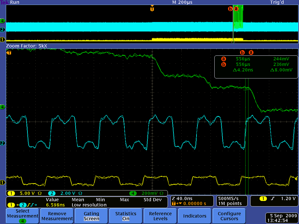
In principle you are right, for a DC signal that should not matter. But in reality the DRS4 output signal is not constant even for a DC signal. When you switch from one sampling cell to another during readout, there is something called "charge injection". This causes the output to change up to several 10 mV. After 28 ns this is mostly settled, but not completely, since the DRS4 output driver has a relatively low bandwidth (~50 MHz). Furthermore, the signal line between the DRS4 and the ADC is not terminated, so you have some reflections going forth and back. In addition, you have some crosstalk from the SRCLK signal. So it's better that you sample on each cycle at exactly the same time. Here you see a plot of that (green: DRS4 output, blue: ADC clock, yellow SRCLK):
|
|